


Service Manual
Fuller Medium Heavy Transmissions
TRSM0201
October 2007

For parts or service call us Pro Gear & Transmission, Inc.
1(877) 776-4600
(407)872-1901 parts@eprogear.com
906 W. Gore St. Orlando, FL 32805

Model Designations........................................................................................................................... |
2 |
Description........................................................................................................................................ |
3 |
Specifications.................................................................................................................................... |
4 |
Lubrication......................................................................................................................................... |
5 |
Conversion to Overdrive..................................................................................................................... |
6 |
Clutch Shaft Replacement.................................................................................................................. |
6 |
General Precautions for Disassembly................................................................................................. |
6 |
Detailed Disassembly Instructions...................................................................................................... |
7 |
Exploded Views |
|
Drive Gear............................................................................................................................................ |
8 |
Countershafts..................................................................................................................................... |
11 |
Reverse Idler Shaft............................................................................................................................ |
11 |
Reverse Idler Gear and Shaft............................................................................................................. |
14 |
Mainshaft........................................................................................................................................... |
14 |
Tailshaft............................................................................................................................................. |
14 |
Tailshaft and Rear Bearing Cover....................................................................................................... |
17 |
Shifting Bar Housing......................................................................................................................... |
17 |
Inspection.......................................................................................................................................... |
17 |
Torque Ratings................................................................................................................................... |
21 |
Gasket Location................................................................................................................................. |
21 |
Preventative Maintenance Check Chart.............................................................................................. |
25 |
General Precautions for Reassembly................................................................................................. |
25 |
Detailed Reassembly Instructions...................................................................................................... |
25 |
Tool Reference................................................................................................................................... |
25 |
Gear Chart for Part Numbers............................................................................................................. |
26 |
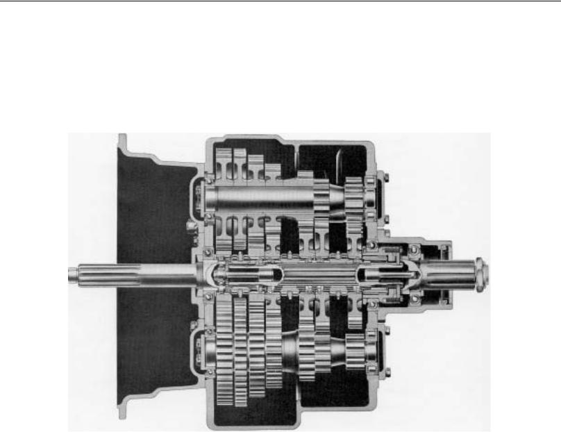
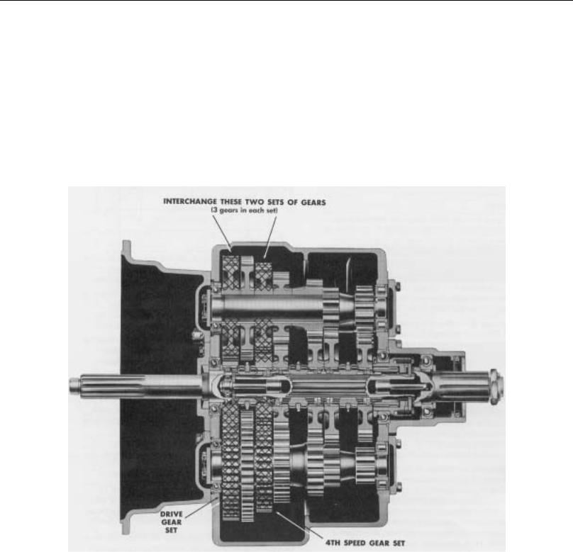
DESCRIPTION
CUTAWAY OF FIVE SPEED
TWIN-COUNTERSHAFT TRANSMISSION
2

MODEL DESIGNATIONS
|
|
MODEL DESIGNATIONS |
T |
= |
Twin Countershaft Type |
O |
= |
Used as a letter, denotes overdrive model |
09 |
= |
900 lbs. ft. capacity rating |
05 |
= |
Five speeds |
“A”, “B”. etc. |
= |
Following numbers indicates a specific set of ratios |
|
|
|
Since the models in the T-905 series are identical in construction, references in this manual apply to all models unless stated otherwise. This includes models not listed above which may have other ration combinations, designated by letters following the numerals.
PART NUMBERS SHOWN IN THIS MANUAL ARE SUBJECT TO CHANGE AND APPLY ONLY AT TIME OF PRINTING.
3
DESCRIPTION
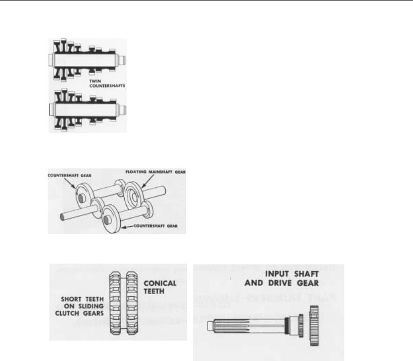
The T-905 model transmissions have five forward speeds and one reverse speed, and are designed for heavy duty vehicles. These models are of twin countershaft design which divides the torque equally between shafts and gears, providing a high capacity to weight ratio.
The countershafts, identical except for the PTO gears, are short and bearings are of a relative low capacity due to the split torque principle. All gears have spur type teeth.
The mainshaft floats free, receiving only minor radial loads. Mainshaft vertical displacement to conform to clutched gear position is allowed by rod-like springs which resist float to right or left.
The mainshaft gears are not jounalled to the mainshaft, but are located axially by washers and held in position by rotation of the countershaft gears; this eliminates the need for bushings and sleeves. Because of equal tooth loading on each side of gear, pressure is reduced and gear face width can be narrowed. Gears are clutched by internal splines in hubs of gears. The sliding clutch gears with short, conical clutching teeth provide shorter and easier shifts.
The input shaft and drive gear are not integral, thus they can be changed individually.
4

DESCRIPTION
5

SPECIFICATIONS
SPECIFICATIONS
GEAR RATIOS
T-905A |
T-905B |
TO-905A |
TO-905B |
SPEEDOMETER DRIVE
Provision is made in the rear bearing cover for the installation of speedometer gears and the attachment of cable.
Fifth |
1.00 |
1.00 |
0.65 |
0.86 |
MAGNETIC OIL CLEANERS
Fourth |
1.54 |
1.16 |
1.00 |
1.00 |
Third |
2.38 |
2.04 |
1.54 |
1.76 |
Second |
3.75 |
3.75 |
2.44 |
3.23 |
First |
6.35 |
6.35 |
4.12 |
5.47 |
Reverse |
6.48 |
6.48 |
4.21 |
5.58 |
SEE PAGE 68
Clutch Release Mechanism
Clutch release bearing carrier, release bearing, extended front bearing cover, release yoke and pedal shafts furnished with transmission for use with single or two plate, push type clutches. Flat type front bearing cover furnished for use with single or two plate, pull type clutches.
Power Take-Off
Openings
Bottom: SAE standard heavy-duty type, short length.
Right Side: SAE standard regular-duty type, short length.
Two magnetic discs are installed in bottom of case to catch and hold metallic particles deposited in the oil.
OIL CAPACITY
Approximately 22 pints, depending on inclination of transmission and engine. Twenty-two pints is a zero degree measurement.
Nominal torque rating |
900 foot-pounds |
Clutch housing size |
SAE No. 1 or 2 |
Weight, with grey iron case |
478 pounds |
Length |
|
From face of clutch housing to rear shoulder |
|
of mainshaft |
27-19/32 inches |
From face of clutch housing to front of |
24-23/32 inches |
companion flange hub |
|
|
|
PTO Drive Gear
Bottom: A 47-Tooth, 6/8 pitch gear on the left counterhshaft.
Right Side: A 45-Tooth, 6/8 pitch gear on the right countershaft.
PTO Drive Gear Speeds
Both turning at .533 engine speed on T-905A and T- 905B models; and at .820 engine speed on TO-905A, and .619 on TO-905B models.
6
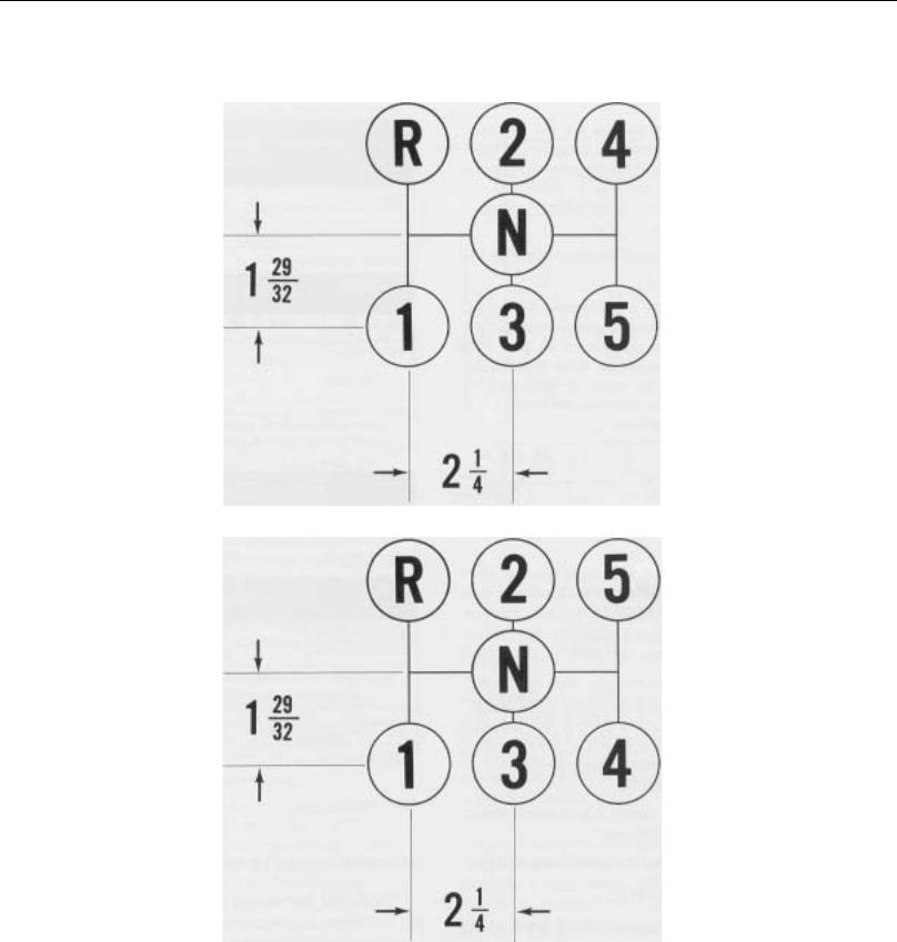
SPECIFICATIONS (SHIFTING DIAGRAMS)
Shifting Diagram for T-905 Model Transmissions
Shifting Diagram for TO-905 Model Transmissions
7
LUBRICATION
Proper lubrication procedures are the key to a good allround maintenance program. If the oil is not doing its job, or if the oil level is ignored, all the maintenance procedures in the world are not going to keep the transmission running or assure long transmission life.
Oil is important, because here are some of the things it must do:
•Provide a protective film - to protect surface of heavily loaded parts such as gear teeth and bearings, thus preventing metal to metal contact which causes scoring, scuffing and seizure.
•Act as a coolant - to dissipate heat.
•Have sufficient fluidity - to follow, coat and cushion all loaded surfaces.
•Be chemically stable - to withstand heat and agitation without separation, gumming-up, oxidizing or corroding.
•Be non-foaming - to prevent excessive foam and increased volume under severe conditions.
•Be free of sediment and water - to prevent sludge and rust.
Fuller Transmissions are designed so that the internal parts operate in a bath of oil circulated by the motion of gears and shafts. Grey iron parts have built-in channels where needed, to help lubricate bearings and shafts.
Thus, all parts will be amply lubricated if these procedures are closely followed:
1.Maintain oil level. Inspect regularly.
2.Change oil regularly.
3.Use the correct grade and type of oil.
LUBRICATION CHANGE AND INSPECTION
HIGHWAY USE
|
First 3,000-5,000 miles |
Change transmission oil on new units. |
|||
|
(4827 - 8045 Km) |
|
|
|
|
|
|
|
|
||
|
Every 5,000 miles |
Inspect oil level. Check for leaks. |
|||
|
(8045 Km) |
|
|
|
|
|
|
|
|
||
|
Every 50,000 miles |
Change transmission oil. |
|||
|
(80,450 Km) |
|
|
|
|
|
|
|
|
|
|
|
|
OFF-HIGHWAY |
|
|
|
|
|
|
|
||
|
First 30 hours |
Change transmission oil on new units. |
|||
|
|
|
|
||
|
First 40 hours |
Inspect oil level. Check for leaks. |
|||
|
|
|
|
||
|
Every 500 hours |
Change transmission oil where severe |
|||
|
|
dirt conditions exist. |
|
|
|
|
|
|
|
||
|
Every 1,000 hours |
Change transmission oil (Normal off- |
|||
|
|
highway use). |
|
|
|
|
|
|
|||
|
Change Oil Filter Element, If So Equipped, At Each Oil Change. |
||||
|
|
|
|||
|
|
|
|||
|
RECOMMENDED LUBRICANTS |
||||
|
ON-HIGHWAY VEHICLES |
|
|
||
|
|
|
|
|
|
|
TYPE |
|
GRADE |
TEMPERATURE |
|
|
|
|
|
|
|
|
Heavy Duty Engine Oil MIL-L- |
SAE 50 or |
Above + 10°F. |
||
|
2104C, or MIL-L-46152, or |
SAE 40 |
(-12.5°C.) |
||
|
API-SE, or API-CC |
|
SAE 30 |
Below + 10°F. |
|
|
|
|
|
|
|
|
Mineral Gear Oil |
|
SAE 90 |
Above + 10°F. |
|
|
|
|
SAE 80W |
Below + 10°F. |
|
|
|
|
|
|
|
|
|
OFF-HIGHWAY |
|
|
|
|
|
|
|
|
|
|
Heavy Duty Engine Oil MIL-L- |
SAE 50 or |
Above + 10°F. |
||
|
2104C, or MIL-L-46152, or |
SAE 40 |
Below + 10°F. |
||
|
API-SE, or API-CC |
|
SAE 30 |
|
|
Special Recommendation - For extreme cold weather where temperature is consistently below 0°F.
Heavy Duty Engine Oil MIL-L- |
SAE 20W |
Below 0°F. |
2104C, or MIL-L-46152, or |
|
(-18°C.) |
API-SE, or API-CC |
|
|
4. Buy from a reputable dealer.
Miscellaneous Lubricants
O-Rings and Surfaces - Dowing Corning #200 Silicone,
30,000 Centistokes. Union Carbide L-45 Silicone, 30,000
Centistokes.
8
Lubrication
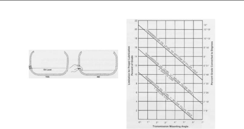
Proper Oil Level
Make sure oil is level with filler opening. Because you can reach oil with your finger does not mean oil is at proper level.
Draining Oil
Drain transmission while oil is warm. To drain oil, remove the drain plug at bottom of case. Clean the drain plug before re-installing.
Refilling
Clean area around filler plug and remove plug from side of case. Fill transmission to the level of the filler opening. If transmission has two filler openings, fill to level of rear opening on single countershaft models; fell to level of both openings on twin countershaft models.
The exact amount of oil will depend on the transmission inclination and model. In every instance, fill to the level of the filler opening.
Do not over fill. This will cause oil to be forced out of the case through mainshaft openings.
Adding Oil
It is recommended that types and brands of oil should not be intermixed because of possible incompatibility.
Operating Temperature
It is important that the transmission operating temperature does not exceed 250°F. (120°C.) for an extended period of time. Operating temperatures above 250°F. will cause breakdown of the oil and shorten transmission life.
The following conditions in any combination can cause operating temperatures of over 250°F: (1) Operating consistently at roadspeeds under 20 MPH, (2) High engine RPM, (3) High ambient temperature, (4) Restricted air flow around transmission, (5) Exhaust system too close to transmission, (6) high horsepower, over-drive operation. High operating temperatures may require more frequent oil changes.
External cooler kits are available to keep the transmission operating temperature under 250°F. when the conditions described above are encountered.
If the transmission operating angle is more than 12 degrees, improper lubrication can occur. The operating angle is the transmission mounting angle in the chassis plus the percent of upgrade (expressed in degrees).
The above chart illustrates the safe percent of upgrade on which the transmission can be used with various chassis mounting angles. For example: If you have a 4 degree transmission mounting angel, then 8 degrees (or 14 percent of grade) is equal to the limit of 12 degrees. If you have a 0 degree mounting angle, the transmission can be operated on a 12 degree (21 percent) grade.
Anytime the transmission operating angle of 12 degrees is exceeded for an extended period of time the transmission should be equipped with an oil pump or cooler kit to insure proper lubrication.
Note on the chart the effect low oil levels can have on safe operating angles. Allowing the oil level to fall ½” below the filler plug hole reduces the degree of grade by approximately 3 degrees (5.5)
PROPER LUBRICATION LEVELS ARE IMPORTANT!
9
CONVERSION TO OVERDRIVE
TO CONVERT FROM T-905A To
TO-905A, or T-905B to TO-905B
To convert from a T-905A or T-905B to an overdrive model TO-905A or TO-905B the 4th speed gear on the mainshaft and mating gears, one on each countershaft, are interchanged with the main drive gear and mating countershaft drive gears.
The transmission must be completely disassembled as the countershaft gears must be removed and interchanged.
Extra parts, other than gaskets are not needed to make the conversion. A new drive gear bearing nut may be needed as this part may be damaged during removal.
10

SPECIAL PROCEDURE FOR CHANGING THE CLUTCH (INPUT) SHAFT
In some case it may be necessary to remove only the input shaft due to clutch wear on the splines. In these cases, the input shaft can be removed without disassembling the transmission other than removing the shift bar housing. Removal of the clutch housing is optional. The following is the detailed procedure:
Disassembly
1.Remove the gear shift lever housing and shift bar housing from transmission.
2.Remove the front bearing cover.
3.Remove the drive gear bearing nut.
4.Move the drive gear assembly as far forward as possible and remove the drive gear bearing.
5.Remove the spacer from input shaft.
6.From the front, remove the snap ring from ID of drive gear.
7.Pull the input shaft forward and from splines of drive gear.
Reassembly
1.Install new input shaft into splines of drive gear just far enough to expose snap ring groove in ID of drive gear.
2.Install snap ring in ID of drive gear.
3.Install spacer on shaft.
4.IMPORTANT - To prevent damaging the front quill when installing bearing, move the 4th & 5th speed sliding clutch gear forward to contact end of input shaft in hub of drive gear. Block between rear of sliding clutch and front of the 4th speed gear. When installing bearing this will hold input shaft away from quill.
5.Install drive gear bearing on shaft and into case bore, making sure blocking remains in place.
6.Remove blocking from mainshaft and install the drive gear bearing nut, left-hand thread. Use Loctite sealant on threads of nut and shaft.
7.Peen nut into milled slot in shaft.
8.Re-install front bearing cover, shifting bar housing and gear shift lever housing.
NOTE: The above instructions are for changing the input shaft only. To change the drive gear, removal of the mainshaft and countershaft bearings is necessary.
11
DISASSEMBLY PRECAUTIONS
GENERAL PRECAUTIONS FOR DISASSEMBLY
Important: Read this section before starting the detailed disassembly procedures.
It is assumed in the detailed disassembly instructions that the transmission lubricant has been drained and the transmission has been removed from the chassis.
Removal of the gear shift lever housing assembly is included in the detailed instructions; however, this assembly must also be removed from transmission before removing unit from vehicle.
Follow each procedure closely in each section, making use of both the text and pictures.
1.BEARINGS - Carefully wash and relubricate all bearings as removed and protectively wrap until ready for use. Remove bearings with pullers designed for this purpose.
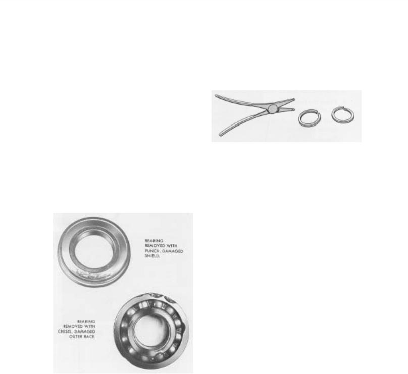
2.SNAP RINGS - Remove snap rings with pliers designed for this purpose. Rings removed in this manner can be reused.
3.INPUT SHAFT - The clutch or input shaft can be removed without removing the countershafts or mainshaft (Refer to Page 11).
4.CLEANLINESS - Provide a clean place to work. It is important that no dirt or foreign material enters the unit during repairs. The outside of the unit should be carefully cleaned before starting the disassembly.
Dirt is abrasive and can damage bearings.
5.WHEN DRIVING - Apply force to shafts, housings, etc., with restraint. Movement of some parts is restricted. Do not apply force after the part being driven stops solidly. Use soft hammers and bars for all disassembly work.
12

DETAILED DISASSEMBLY INSTRUCTIONS
DETAILED DISASSEMBLY INSTRUCTIONS
A.To Remove and Disassemble the Gear Shift Lever Housing Assembly
1.Turn out the four capscrews and lift the gear shift lever housing, or remote control housing, from the shifting bar housing (See Illustration 1).
2.Remove the ball grip and rubber dust cover from the gear shift lever.’
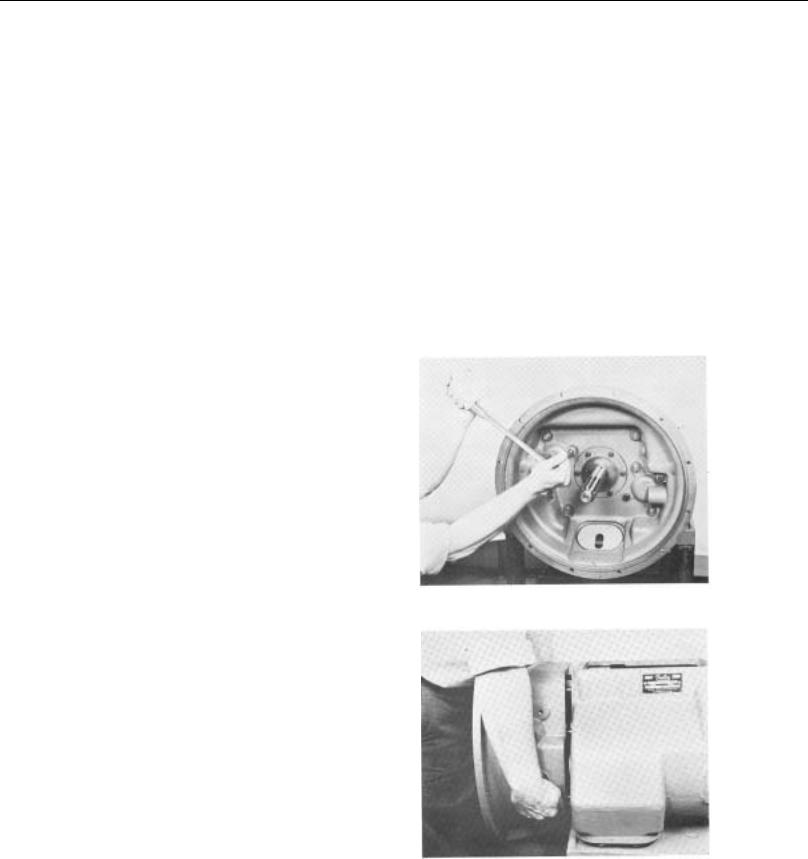
3.Mount the assembly in a vise with the large bottom opening upwards.
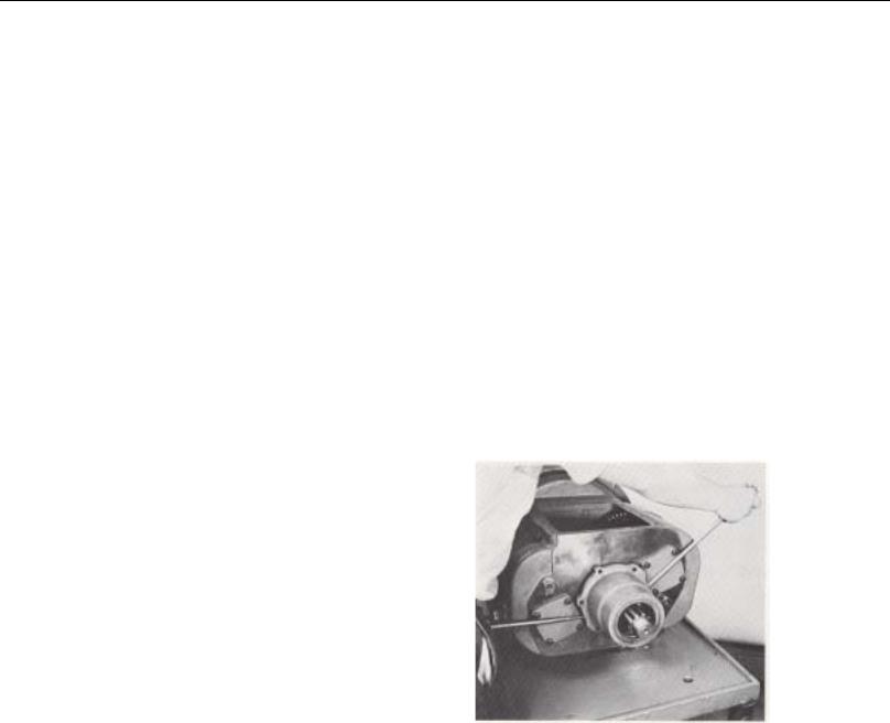
4.Free the tension spring by twisting a heavy screwdriver between spring and housing, forcing spring from its seat in housing (See Illustration 2).
5.Remove the tension spring from housing.
6.Withdraw the tension spring washer and gear shift lever out through bottom housing (See Illustration 3).
7.Remove nut and lockwasher from pivot pin.
8.Remove pivot pin by forcing it inward and through wall of housing.
#1 - Lifting gear shift lever housing from shifting bar housing.
#2 - Removing the gear shift lever tension spring from under lugs cast in housing.
#3 - Removing washer and gear shift lever from housing.
13

DISASSEMBLY
#4 - Lifting the shifting bar housing from transmission.
#5 - Removing shifting bar tension springs.
I#6 - Pulling the 4th-5th speed shifting bar from housing.
#7 - Removing interlock pin from neutral notch in the 2nd & 3rd speed shifting bar.
#8 - Two interlock balls are located in front boss, one between each bar.
#9 - Turning companion flange nut from output shaft.
14
DISASSEMBLY
B.To Remove the Shifting Bar Housing Assembly
1.Turn out the attaching capscrews.
2.Jar to break the gasket seal and lift the shifting bar housing from transmission (See Illustration #4).
C.To Disassemble the Shifting Bar Housing Assembly
NOTE: Lay all parts on a clean bench in the order in which they are removed to facilitate reassembly. Keep bars not being removed in the neutral position or interlock parts will lock bars.
1.Turn out the two capscrews and remove the tension spring cover from top of housing.
2.Remove the three tension springs from bores in housing (See Illustration #5).
3.Tilt housing and remove the tension balls installed under the springs.
4.Place the housing in a vise with the left side up; the long bar will be at the bottom.
5.Cut lockwire and remove lockscrews from each bar just prior to its removal.
6.Move the top, 4th-5th speed shifting bar to the front and out of housing, removing shifting yoke from bar (See Illustration #6).
7.Move the center, 2nd-3rd speed shifting bar to the front and out of housing, removing the shifting yoke from bar. As the neutral notch in bar clears housing boss, remove the small interlock pin from bore in neutral notch (See Illustration #7).
8.Move the bottom, 1st-Reverse speed shifting bar to the front and out of housing, removing the shifting yoke and block from bar.
9.Two interlock balls will fall from interlock ball opening in front boss as the last bar is removed (See Illustration #8).
D.To Remove the Companion Flange or Yoke
1.Lock the mainshaft by engaging two speeds with the mainshaft sliding clutch gears.
2.Turn the elastic stop nut from the output shaft (See Illustration #9).
3.Pull the flange or yoke from splines of the tailshaft.
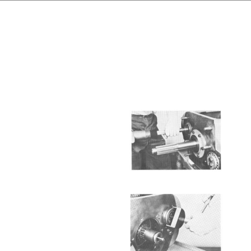
E.To Remove and Disassemble the Rear Bearing Cover Assembly
1.Turn out the attaching capscrews from the rear bearing cover.
2.Pry the bearing cover evenly to the rear to unseat from tailshaft bearing (See Illustration #10).
#10 - Prying rear bearing cover evenly to rear.
3.Remove the bearing cover from tailshaft (See Illustration #11).
4.Remove the speedometer gear, or replacement spacer, and the bearing washer from tailshaft or from cover.
5.Pull the outer bearing from tailshaft. (This bearing may remain in cover; in this case, move the bearing evenly forward and from cover) See Illustration #12.
6.Remove the oil seal from cover if necessary.
15

DISASSEMBLY
#11 - Removing rear bearing cover from tailshaft.
#12 - Pulling the tailshaft outer bearing.
#13 - Removing capscrews from flat keys.
#14 - Removing flat keys from tailshaft. These keys maintain relative position of mainshaft to tailshaft.
#15 - Removing tailshaft from case bore. Start assembly to the rear by prying evenly against bearing snap ring.
#16 - Removing key spacer ring from tailshaft.
#17 - Turning bearing nut from tailshaft, left-hand thread.
16
DISASSEMBLY
F.To Remove and Disassemble the Tailshaft Assembly
1.Cut lockwire and turn out the two 5/16” capscrews from the two flat keys (See Illustration #13).
2.Remove the two flat keys from bores in tailshaft. These keys maintain the position of the mainshaft in relation to tailshaft (See Illustration #14).
3.Move the tailshaft evenly to the rear and from case bore. Moving the mainshaft assembly to the rear will start moving tailshaft from bore (See Illustration #15).
4.Remove the splined coupling gear from mainshaft, or from pocket in tailshaft.
5.Turn out the 5/16” capscrews and remove the key spacer ring from tailshaft (See Illustration #16).
6.Remove the bearing nut from tailshaft, left-hand thread (Illustration #17).
7.Press the front bearing from tailshaft.
G. To Remove the Clutch Housing
NOTE: The clutch housing can be removed at any time during transmission disassembly. However, it must be removed BEFORE the two countershafts can be removed.
1.Remove the clutch release mechanism if the transmission is so equipped.
2.Turn out the four bolts and remove the six nuts and lockwashers from studs at front of case (See Illustration #18).
3.Break gasket seal and pull clutch housing from case (See Illustration #19).
#18 - Turning attaching bolts from clutch housing.
#19 - Removing clutch housing from case.
17
DISASSEMBLY
#20 - Removing snap ring from ID of the mainshaft reverse gear.
#21 - Removing lockplate from left reverse idler shaft.
#22 - Removing left reverse idler shaft with impact puller.
#23 - Removing left reverse idler gear and the two thrust washers from case.
#24 - Removing rear bearing cover from right countershaft.
#25 - Removing bearing retainer plat from front of right countershaft.
18
DISASSEMBLY
H. To Remove the Left Reverse Idler Gear
NOTE: The left reverse idler gear must be removed in order to remove the mainshaft assembly.
1.Move the mainshaft assembly forward as far as possible and the mainshaft reverse gear to the rear against case.
2.Remove the snap ring from ID of the mainshaft reverse gear (See Illustration #20).
3.Move the 1st-Reverse sliding clutch gear and the reverse gear as far forward as possible on the mainshaft.
4.Turn out capscrew at rear of transmission and remove the lock plate from slot in the idler shaft (See Illustration #21).
5.Use impact puller to withdraw the idler shaft from case (See Illustration #22).
6.Remove the reverse idler gear and the two thrust washers from case (See Illustration #23).
7.Remove inner race of bearing from gear bore.
8.Press needle bearing from gear bore.
9.Remove plug from idler shaft if necessary.
I. To Remove Bearings from Right Countershaft
NOTE: In order to remove the mainshaft assembly it will be necessary to move the right countershaft by removing bearings.
1.Turn out capscrews and remove rear bearing cover from right countershaft (See Illustration #24).
2.Cut lockwire, turn out the two capscrews and remove bearing retainer plate from front of right countershaft (See Illustration #25).
3.Use soft bar and mall to move the right countershaft to the rear until snap ring groove in rear bearing is exposed. Do not unseat shaft from front bearing (See Illustration #26).
4.Use puller to remove rear bearing from shaft. A snap ring can be installed in rear bearing groove to facilitate pulling if groove type puller is not available (See Illustration #27).
5.Use soft bar and mall to move right countershaft forward to partially unseat front bearing (See Illustration #28).
6.Remove front bearing from countershaft (See Illustration #29).
#26 - Moving right countershaft to the rear to expose rear bearing. DO NOT UNSEAT FRONT BEARING FROM SHAFT.
#27 - Pulling rear bearing from right countershaft.
19
 Loading...