


Service Manual
Fuller Mid Range Transmissions
TRSM0196
October 2007

For parts or service call us Pro Gear & Transmission, Inc.
1(877) 776-4600
(407)872-1901 parts@eprogear.com
906 W. Gore St. Orlando, FL 32805

Caution -
Before towing the vehicle, be sure to lift the rear wheels off the ground or disconnect the driveline to avoid damage to the transmission during towing.

FOREWARD
This manual has been prepared to provide the customer and the maintenance personnel with information and instructions on the maintenance and repair of the CLARK® Transmission.
Extreme care has been exercised in the design, selection of materials and manufacturing of these units. The slight outlay in personal attention and cost required to provide regular and proper lubrication, inspection at stated intervals, and such adjustments as may be indicated will be reimbursed many times in low cost operation and trouble free service.
In order to become familiar with the various parts of the transmission, its principle of operation, troubleshooting and adjustments, it is urged that the service person study the instructions in this manual carefully and use it as a reference when performing maintenance and repair operations.
Whenever repair or replacement of components parts is required, only Clark-approved parts as listed in the applicable parts manual should be used. Use of “will-fit” or non-approved parts may endanger proper operation and performance of the equipment. The Clark Equipment Company does not warrant repair or replacement parts, nor failures resulting from the use thereof, which are not supplied by or approved by the Clark Equipment Company.
IMPORTANT: Always furnish the Distributor with the transmission serial and model number when ordering parts.

The CL455 is our “soft fourth” transmission, with the 28 percent step from fourth to fifth. The soft fourth allows the use of a two speed axle without the confusing swap shift in fourth and fifth speeds.
The CL457 is the conventional short fourth 5-speed, for those that still prefer it.
And the CL450 is a straight 5-speed with an 8 to 1 low and reverse ratio . . . a real benefit when a steep grade must be negotiated.
|
|
MODELS |
|
|
|
|
|
|
CL455 |
CL457 |
CL450 |
Speed |
(Soft 4th) |
(Short 4th) |
(Straight 5-speed |
|
|
|
|
|
|
|
|
Fifth |
Direct |
Direct |
Direct |
|
|
|
|
Fourth |
1.28 |
1.17 |
1.48 |
|
|
|
|
Third |
2.13 |
2.13 |
2.48 |
|
|
|
|
Second |
3.78 |
3.78 |
4.35 |
|
|
|
|
First |
6.99 |
6.99 |
8.05 |
|
|
|
|
Reverse |
6.99 |
6.99 |
8.05 |
|
|
|
|
Nomenclature-CL Stands for Clark. 1st number stands for nominal torque capacity (nom. 400/lb./ft.). 2nd number is number of forward speeds. 3rd number denotes specific gear set.
Constant mesh in all gears, including low and reverse, is a CL450 feature as is helical gearing throughout, including low and reverse.
The Clark split-pin synchronizer is used in 2nd, 3rd 4th and 5th gears. Greater bearing capacity in the CL450 is achieved by the use of numerous needle roller bearings, and tapered roller bearings at main support locations.
Shift forks have replaceable bronze inserts. The shift pattern is of the standard progression type with all shifts having the same throw at the lever.
A
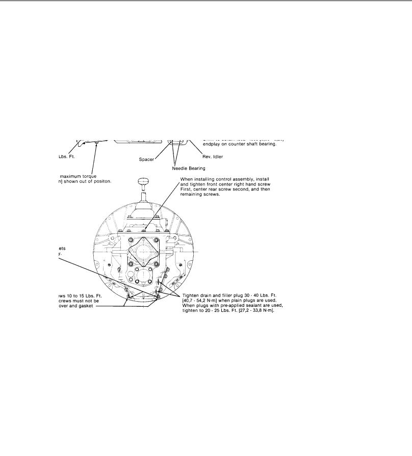
CL 450 SERIES
ASSEMBLY INSTRUCTIONS
Unless otherwise specified:
Tighten all capscrews 20 to 25 lbs. ft. [27,2 - 33,8 N.m].
Use a Grade #2 Multi-Purpose Grease to retain needle rollers in reverse idler gear bore during assembly.
Apply a thin coat of Loctite 510 Gasket Eliminator to the O.D. of all oil seals and countershaft front bore plug before assembly.
Hand-spin idler gear and countershaft assemblies after each is installed on their bearings in trans. case. Both must spin freely and smoothly.
Check all mainshaft constant-mesh gears to make sure they rotate freely on mainshaft.
Fasteners that are removed and reused, apply Locktite 262 Adhesive/Sealant.
B

THE CLARK SYNCHRONIZER
AND HOW IT WORKS FOR YOU
The Clark split-pin synchronizer prevents the clashing of the gears and increase the speed of shifting.
In a conventional transmission which does not have synchronizers the absence of gear clashing is dependent entirely on the skill of the truck driver. By double-clutching and split second timing of engine speeds with the gear shifting movement, a driver can synchronize the speeds of the engaging gears and thereby prevent the damage to gears by clashing when a fast shift. The splint-pin sychronzier performs the same function with or without the “double-clutching” operating even though the driver does not accurately time his gear shifting movements. It also mechanically prevents the driver from completing the shift to the point of gear engagement until the engaging gears have reached the same or synchronous speeds. This is known as the blocking action of the synchronizer and it is this action that makes the operation of shifting a transmission having synchronizers different from one which does not have synchronizers.
Upon shifting gears in these synchronized transmissions the first part of the gear shift lever movement brings the blockers into contact. The blockers momentarily prevent further movement of the shift lever and the pressure exerted by the driver to complete the movement, is transferred by the blockers to the synchronizer providing the force necessary to synchronize the gears being engaged. When the engaging gears have reached the same speed, the blockers automatically disengage, permitting the gear shift lever movement to be completed. Therefore, to properly shift a synchronized transmission a steady and continuous pressure must be applied by the driver to the shift lever until the shift is completed. Under normal conditions this action is instantaneous.
Sometimes difficulty is experienced in shifting a synchronizer when the vehicle is standing still. This is caused by the fact that the disengagement of the blockers requires relative rotation and with the vehicle at rest and with the engine clutch released, there may be at times, no relative rotation of the engaging gears. Under these conditions, the same continuous pressure should be applied to the shift lever and at the same time, the clutch should be engaged slightly. This will give sufficient rotation to unblock the synchronizer and allow the shift to be completed without difficulty.
C

RECOMMENDED LUBRICANTS FOR CLARK
MANUALLY SHIFTED TRANSMISSIONS
*Mil-L-2105C Extreme Pressure Lubricant (or API classification GL-5) of the SAE viscosity recommended in the chart at the right is preferred. All lubricants should be backed by the reputation of a wellknow supplier. It is important to specify EP lubricants of the MIL-L- 2105C type only, or of a API classification GL-5.
*Do not use extreme pressure lubricants other than MIL-L-2105C or of a API classification GL-5.
Many EP lubricants contain highly-active chemical compounds that have been formulated to perform satisfactorily in specific types of applications. Severe corrosion, residual deposits, and inadequate lubrication may result from improper application. Use of EP lubricants other that MIL-L-2105C or of a API classification GL-5 may result in failure and/or impaired operation.
DRAINING ECONOMY - The object in draining the transmission oil periodically is to eliminate possible bearing surface abrasion and attendant wear. Minute particles of metal, the product of normal wear in service, are deposited in and circulate with the transmission oil. The oil changes chemically, due to its repeated heating and cooling, also the terrific churning it undergoes in the presence of air. It is desirable to drain out this used oil after the first 1,000 miles (1609,0 Km) of service (regardless of type of service). Subsequent drains should be made every 24,000 miles (38616,0 Km) or six (6) months (whichever
comes first) for highway service, and every 8,000 to 10,000 miles [12872,0-16090,0 Km] or six (6) months (whichever comes first) “on-off” highway and “pick-up and delivery” types of service. Do this only when the transmission is thoroughly warm.
FLUSHING - After draining, flushing is desirable. Replace the drain plug and fill the transmission to the proper level with a light flushing oil. Drive the transmission for a short period at fast idle in such a manner that the gears in the transmission are rotating without load. This washes out the old oil clinging to the interior of the gear case, covers and shifter rails. BE SURE TO DRAIN OUT ALL of the flushing oil before attempting to refill with new oil. This flushing procedure is most important after first drain.
REFILL - First, removal all dirt around the filler plug, Then refill with new oil of a grade recommended for the existing season and prevailing service. Fill to the bottom of the level testing plug positioned on the side of the transmission. DO NOT OVERFILL, as the excess quantity will serve no useful purpose. If the oil level is too high, it will cause excessive oil churning and high oil temperature and possible leakage.
INSPECTION - Oil level inspection should be made every 6,000 miles [9654,0 Km] which usually coincides with the vehicle manufacturers chassis lube procedure. Always clean around filler plug before inspection. Add sufficient oil to maintain correct level.
D

CLARK
E

|
|
CL450 -SERIES TRANSMISSION |
|
||
ITEM |
DESCRIPTION |
QTY. |
52 |
Mainshaft Rear Bearing Cap .................................................... |
1 |
1 |
Control Cover Assembly .......................................................... |
1 |
53 |
Mainshaft Rear Bearing Cap Shim........................................ |
AR |
2 |
Control Cover Screw Lockwasher .......................................... |
13 |
54 |
Speedometer Driven Gear ...................................................... |
1 |
3 |
Control Cover Screw .............................................................. |
13 |
55 |
Mainshaft Rear Bearing Cap Stud............................................ |
4 |
4 |
Control Cover Gasket .............................................................. |
1 |
56 |
Mainshaft Rear Bearing Cup.................................................... |
1 |
5 |
Mainshaft 2nd Gear.................................................................. |
1 |
57 |
Mainshaft Flange Nut............................................................... |
1 |
6 |
Mainshaft 2nd Gear Roller Bearing .......................................... |
1 |
58 |
Output Flange .......................................................................... |
1 |
7 |
Split Washer Retainer Ring ...................................................... |
1 |
59 |
Mainshaft Rear Bearing Cap Oil Seal ....................................... |
1 |
8 |
Mainshaft 2nd Gear Split Washer............................................. |
2 |
60 |
Speedometer Drive Gear Tube Nut .......................................... |
1 |
9 |
Split Washer Lock Ball ............................................................. |
1 |
61 |
Speedometer Driven Gear ....................................................... |
1 |
10 |
Mainshaft 1st Gear ................................................................. |
1 |
62 |
Mainshaft Rear Bearing Cap Bolt............................................. |
4 |
11 |
Mainshaft 1st Gear Bearing...................................................... |
1 |
63 |
Mainshaft Rear Bearing Cap Bolt Washer ................................ |
4 |
12 |
Mainshaft 1st & Reverse Shift Hub .......................................... |
1 |
64 |
Countershaft Rear Bearing Capscrew ...................................... |
4 |
13 |
Mainshaft ................................................................................. |
1 |
65 |
Countershaft Rear Bearing Cap ............................................... |
1 |
14 |
Mainshaft Reverse Gear Roller Bearing.................................... |
1 |
66 |
Countershaft Rear Bearing Cap Shim ................................... |
AR |
15 |
Mainshaft Reverse Gear ........................................................... |
1 |
67 |
Countershaft Rear Bearing Cup ............................................... |
1 |
16 |
Mainshaft Rear Bearing Thrust Washer ................................... |
1 |
68 |
Reverse Idler Shaft .................................................................. |
1 |
17 |
Mainshaft Rear Bearing Cone................................................... |
1 |
69 |
Reverse Tab Lock Screw ......................................................... |
1 |
18 |
2nd & 3rd Gear Shift Hub Sleeve ............................................. |
1 |
70 |
Reverse Idler Shaft Lock ........................................................ |
1 |
19 |
2nd Gear Shift Hub Sleeve Retainer Ring................................. |
1 |
71 |
Mainshaft Roller Bearing Washer Retainer Ring...................... |
1 |
20 |
2nd & 3rd Gear Synchronizer Assembly .................................. |
1 |
72 |
Mainshaft Roller Bearing Washer ............................................ |
1 |
21 |
3rd Gear Synchronizer Cup ...................................................... |
1 |
73 |
Mainshaft Roller Bearing ...................................................... |
14 |
22 |
Mainshaft 3rd Gear Bearing .................................................... |
1 |
74 |
Main Drive Gear ...................................................................... |
1 |
23 |
Mainshaft 3rd Gear .................................................................. |
1 |
75 |
Main Drive Gear Bearing Cone ................................................ |
1 |
24 |
Mainshaft 3rd Gear Locating Washer Ball ................................ |
1 |
76 |
Main Drive Gear Bearing Cup ................................................. |
1 |
25 |
Mainshaft 3rd Gear Locating Washer....................................... |
1 |
77 |
Main Drive Gear Bearing Cap Oil Seal...................................... |
1 |
26 |
3rd Gear Locating Washer Retaining Ring ............................... |
1 |
78 |
Main Drive Gear Bearing Cap Gasket ....................................... |
1 |
27 |
Mainshaft 4th Gear Bearing .................................................... |
1 |
79 |
Main Drive Gear Bearing Cap................................................... |
1 |
28 |
Mainshaft 4th Gear .................................................................. |
1 |
80 |
Main Drive Gear Bearing Capscrews ....................................... |
4 |
29 |
4th & 5th Synchronizer Cup..................................................... |
1 |
81 |
Transmission Case .................................................................. |
1 |
30 |
4th & 5th Synchronizer Assembly............................................ |
1 |
82 |
Countershaft Front Bearing Cup .............................................. |
1 |
31 |
4th & 5th Synchronizer Cup..................................................... |
1 |
83 |
Countershaft Front Bearing Race Locator Ring ....................... |
1 |
32 |
4th & 5th Shift Hub Sleeve ...................................................... |
1 |
84 |
Countershaft Front Bore Plug .................................................. |
1 |
33 |
4th & 5th Shift Hub Thrust Bearing......................................... |
1 |
85 |
Clutch Shaft Grease Fitting ...................................................... |
2 |
34 |
4th & 5th Shift Hub Thrust Bearing Race................................. |
1 |
86 |
Clutch Housing Cover ............................................................. |
1 |
35 |
Countershaft Front Bearing Cone ............................................. |
1 |
87 |
Clutch Housing Cover Screw Lockwasher ............................... |
2 |
36 |
Countershaft Drive Gear Retainer Ring .................................... |
1 |
88 |
Clutch Housing Cover Screw ................................................... |
2 |
37 |
Countershaft Drive Gear........................................................... |
1 |
89 |
Clutch Housing........................................................................ |
1 |
38 |
Countershaft 4th Gear.............................................................. |
1 |
90 |
Clutch Pedal Shaft Bushing .................................................... |
4 |
39 |
Countershaft Gear Key ............................................................. |
2 |
ITEM |
DESCRIPTION |
QTY. |
40 |
Countershaft 3rd Gear.............................................................. |
1 |
91 |
Clutch Housing to Case Screw ................................................ |
4 |
41 |
Countershaft 2nd Gear ............................................................. |
1 |
92 |
Clutch Housing to Case Screw Lockwasher ............................ |
4 |
42 |
Countershaft ............................................................................ |
1 |
93 |
P.T.O. Cover Lockscrew ......................................................... |
12 |
43 |
Countershaft Rear Bearing Cone .............................................. |
1 |
94 |
P.T.O. Cover Plate .................................................................... |
2 |
44 |
Reverse Idler Gear Thrust Washer ........................................... |
1 |
95 |
P.T.O. Cover Plate Gasket......................................................... |
2 |
45 |
Reverse Idler Gear .................................................................. |
1 |
96 |
Magnetic Drain Plug ................................................................ |
1 |
ITEM |
DESCRIPTION |
QTY. |
97 |
Filter Plug ................................................................................ |
1 |
46 |
Reverse Idler Gear Bearing .................................................... |
26 |
98 |
Name Plate Screw ................................................................... |
2 |
47 |
Reverse Idler Gear Bearing Spacer........................................... |
1 |
99 |
Name Plate .............................................................................. |
1 |
48 |
Reverse Idler Gear Bearing .................................................... |
26 |
|
|
|
49 |
Reverse Idler Thrust Washer.................................................... |
1 |
AR = As Required |
|
|
50 |
Mainshaft Rear Bearing Cap Nut .............................................. |
4 |
|
||
51 |
Mainshaft Rear Bearing Cap Washer........................................ |
4 |
|
|
|
F
CLARK
F
 Loading...