


 Loading...
Troubleshooting Guide
Fuller® Heavy-Duty Transmissions
TRTS0910 EN-US
October 2007

Models
FR-11210B |
RTLO-14610B |
RTLOF-15610B-T2 |
FR-12210B |
RTLO-14610B-T2 |
RTLOF-16610B |
FR-13210B |
RTLO-14613B |
RTLOF-16610B-T2 |
FR-14210B |
RTLO-14618A |
RTLOF-16618A |
FR-15210B |
RTLO-14713A |
RTXF-15615 |
FR-9210B |
RTLO-14718B |
RTLOF-16713A |
FRF-11210B |
RTLO-14913A |
RTLOF-16713A-T2 |
FRF-12210B |
RTLO-14918B |
RTLOF-16718B |
FRF-13210B |
RTLO-14918B-T2 |
RTLOF-16913A |
FRF-14210B |
RTLO-15610B |
RTLOF-16913A-T2 |
FRF-15210B |
RTLO-15610B-T2 |
RTLOF-16918B |
FRF-9210B |
RTLO-16610B |
RTLOF-16918B-T2 |
FRO-11210B |
RTLO-16610B-T2 |
RTLOF-17610B |
FRO-11210C |
RTLO-16618A |
RTLOF-17610B-T2 |
FRO-12210B |
RTXF-14710C |
RTLOF-18610B |
FRO-12210C |
RTLO-16713A |
RTLOF-18718B |
FRO-13210B |
RTLO-16713A-T2 |
RTLOF-18913A |
FRO-13210C |
RTLO-16718B |
RTLOF-18913A-T2 |
FRO-14210B |
RTLO-16913A |
RTLOF-18918B |
FRO-14210C |
RTLO-16913A-T2 |
RTLOF-18918B-T2 |
FRO-15210B |
RTLO-16918B |
RTLOF-20913A |
FRO-15210C |
RTLO-16918B-T2 |
RTLOF-20918B |
RTXF-14615 |
RTLO-17610B |
RTLOF-20918B-T2 |
RTXF-14708LL |
RTLO-17610B-T2 |
RTLOF-22918B |
FRO-16210B |
RTLO-18610B |
RTLOFC-16909A-T2 |
FRO-16210C |
RTLO-18610B-T2 |
RTO-11607L |
FRO-17210C |
RTLO-18718B |
RTO-11607L |
FRO-18210C |
RTLO-18718B-T2 |
RTXF-15710B |
FROF-11210B |
RTLO-18913A |
RTO-11607LL |
FROF-11210C |
RTLO-18913A-T2 |
RTO-11607LL |
FROF-12210B |
RTLO-18918B |
RTO-11608LL |
FROF-12210C |
RTLO-18918B-T2 |
RTO-11707DLL |
FROF-13210B |
RTLO-20913A |
RTO-11707LL |
FROF-13210C |
RTLO-20918B |
RTO-11708LL |
FROF-14210B |
RTLO-20918B-T2 |
RTO-11709MLL |
FROF-14210C |
RTLO-22918B |
RTO-11908LL |
FROF-15210B |
RTLOC-16909A-T2 |
RTO-11909ALL |
FROF-15210C |
RTXF-14715 |
RTO-11909MLL |
FROF-16210B |
RTLOF-11610B |
RTO-13707DLL |
FROF-16210C |
RTLOF-11610B-T2 |
RTO-13707MLL |
RT-7608LL |
RTLOF-12610B |
RTO-14608LL |
RT-8608L |
RTLOF-12610B-T2 |
RTO-14709MLL |
RT-8908LL |
RTLOF-12713A |
RTO-14908LL |
RTF-8608L |
RTLOF-12913A |
RTO-14909ALL |
RTF-8908LL |
RTLOF-13610B |
RTO-14909MLL |
RTLO-11610B |
RTLOF-13610B-T2 |
RTO-16908LL |
RTXF-14709H |
RTLOF-14610B |
RTO-16909ALL |
RTXF-14710B |
RTLOF-14610B-T2 |
RTOF-11607L |
RTLO-11610B-T2 |
RTLOF-14613B |
RTOF-11607LL |
RTLO-12610B |
RTLOF-14618A |
RTOF-11608LL |
RTLO-12610B-T2 |
RTLOF-14713A |
RTXF-15710C |
RTLO-12713A |
RTLOF-14718B |
RTOF-11707LL |
RTLO-12913A |
RTLOF-14913A |
RTOF-11708LL |
RTLO-13610B |
RTLOF-14918B |
RTOF-11709MLL |
RTLO-13610B-T2 |
RTLOF-14918B-T2 |
RTOF-11908LL |
RTLO-14610A |
RTLOF-15610B |
RTOF-11909ALL |
RTOF-11909MLL RTOF-13707DLL RTOF-13707MLL RTOF-14608LL RTOF-14708LL RTOF-14709MLL RTOF-14908LL RTOF-14909ALL RTOF-14909MLL RTOF-16908LL RTOF-16909ALL RTX-11509 RTX-11608LL RTX-11609A RTX-11609B RTX-11609P RTX-11609R RTXF-15715 RTX-11610 RTX-11615 RTX-11708LL RTX-11709A RTX-11709B RTX-11709H RTX-11710B RTX-11710C RTX-11715 RTX-12509 RTX-12510 RTX-12515 RTX-12609A RTX-12609B RTX-12609P RTX-12609R RTX-12610 RTX-12709A RTX-12709B RTX-12709H RTX-12710B RTX-12710C RTXF-16709B RTX-13609A RTX-13609B RTX-13609P RTX-13609R RTX-13709H RTX-13710B RTX-13710C RTX-14608LL RTX-14609A RTX-14609B RTX-14609P RTX-14609R RTX-14610 RTX-14615 RTX-14708LL
RTX-14709A
RTX-14709B RTX-14709H RTX-14710B RTX-14710C RTX-14715 RTX-15615 RTXF-16709H RTX-15710B RTX-15710C RTX-15715 RTX-16709B RTX-16709H RTX-16710B RTX-16710C RTXF-11509 RTXF-11608LL RTXF-11609A RTXF-11609B RTXF-11609P RTXF-11609R RTXF-11610 RTXF-11615 RTXF-11708LL RTXF-11709H RTXF-11710B RTXF-11710C RTXF-11715 RTXF-12509 RTXF-12510 RTXF-16710B RTXF-12515 RTXF-12609A RTXF-12609B RTXF-12609P RTXF-12609R RTXF-12610 RTXF-12709H RTXF-12710B RTXF-12710C RTXF-13609A RTXF-13609B RTXF-13609P RTXF-13609R RTXF-13709H RTXF-13710B RTXF-13710C RTXF-14608LL RTXF-14609A RTXF-14609B RTXF-14609P RTXF-14609R RTXF-14610 RTXF-16710C
Warnings
WARNINGS
 WARNING
Before starting a vehicle always be seated in the driver’s seat, place the transmission in neutral, set the parking brakes and disengage the clutch.
 WARNING
Before working on a vehicle, place the transmission in neutral, set the parking brakes and block the wheels.
 WARNING
Before towing the vehicle, place the transmission in neutral and lift the rear wheels off the ground or disconnect the driveline to avoid damage to the transmission during towing.
Warnings
0

Table of Contents
FOREWORD . . . . . . . . . . . . . . . . . . . . . . . . . . . 1
TRANSMISSION FUNCTION . . . . . . . . . . . . . . . 2
POWER FLOW . . . . . . . . . . . . . . . . . . . . . . . . . 4
TIMING . . . . . . . . . . . . . . . . . . . . . . . . . . . . . . . 5
Front Section . . . . . . . . . . . . . . . . . . . . . . . . 5
Auxiliary Section . . . . . . . . . . . . . . . . . . . . . 5
COMMON TRANSMISSION COMPLAINTS . . . . 6
Vibration . . . . . . . . . . . . . . . . . . . . . . . . . . . 6
Gear Slipout and Jumpout . . . . . . . . . . . . . . 7
Auxiliary Section . . . . . . . . . . . . . . . . . . . . . 8
Hard Shifting . . . . . . . . . . . . . . . . . . . . . . . . 8
Heat . . . . . . . . . . . . . . . . . . . . . . . . . . . . . . . 9
Noise . . . . . . . . . . . . . . . . . . . . . . . . . . . . . . 9
Transmission Noise . . . . . . . . . . . . . . . . . . . 9
GEARS AND SHAFTS . . . . . . . . . . . . . . . . . . . 11
Clashing . . . . . . . . . . . . . . . . . . . . . . . . . . . 11
Gear Failures . . . . . . . . . . . . . . . . . . . . . . . 11
Manufacturing Marks . . . . . . . . . . . . . . . . . 11
Gear Rattle at Idle . . . . . . . . . . . . . . . . . . . . 12
Shaft Twist and Fracture . . . . . . . . . . . . . . 12
BEARINGS . . . . . . . . . . . . . . . . . . . . . . . . . . . 14
Fatigue . . . . . . . . . . . . . . . . . . . . . . . . . . . . 14
Lubrication . . . . . . . . . . . . . . . . . . . . . . . . . 14
Brinelling . . . . . . . . . . . . . . . . . . . . . . . . . . 15
Fretting . . . . . . . . . . . . . . . . . . . . . . . . . . . . 15
Contamination . . . . . . . . . . . . . . . . . . . . . . 15
Misalignment . . . . . . . . . . . . . . . . . . . . . . . 16
Electric Arcing . . . . . . . . . . . . . . . . . . . . . . 16
TRANSMISSION ALIGNMENT . . . . . . . . . . . . .17 Concentric Alignment of
Transmission to Engine . . . . . . . . . . . . . . . .17 Worn Housings . . . . . . . . . . . . . . . . . . . . . .17 Engine Flywheel Housing Pilot . . . . . . . . . .18 Engine Flywheel Housing Face . . . . . . . . . .18 Flywheel Face . . . . . . . . . . . . . . . . . . . . . . .18 Flywheel Pilot Bore . . . . . . . . . . . . . . . . . . .19 Transmission Clutch Housing . . . . . . . . . . .19
DRIVELINE ANGULARITY . . . . . . . . . . . . . . . .20
Torsional Vibration . . . . . . . . . . . . . . . . . . .20
Taking Readings . . . . . . . . . . . . . . . . . . . . .21
PREVENTIVE MAINTENANCE . . . . . . . . . . . . . .24
Daily . . . . . . . . . . . . . . . . . . . . . . . . . . . . . .24
Every 10,000 Miles . . . . . . . . . . . . . . . . . . .24
Every 20,000 Miles . . . . . . . . . . . . . . . . . . .25
Every 40,000 Miles . . . . . . . . . . . . . . . . . . .26
Every *50,000 Miles . . . . . . . . . . . . . . . . . .26
Fuller® Preventive Maintenance
Recommendations . . . . . . . . . . . . . . . . . . . .26
LUBRICATION . . . . . . . . . . . . . . . . . . . . . . . . .27 Proper Lubrication. . .
the key to long transmission life . . . . . . . . .27
TORQUE RECOMMENDATIONS . . . . . . . . . . . .30
TROUBLESHOOTER’S GUIDELINE . . . . . . . . . .32
CONVERSION TABLE . . . . . . . . . . . . . . . . . . . .35
TOWING OR COASTING . . . . . . . . . . . . . . . . . .37

Foreword
FOREWORD
The purpose of this publication is to provide basic technical information for servicing and repairing heavy duty truck transmissions. A guide to help the mechanic locate the trouble, analyze the cause, and make the necessary repairs. Emphasis is placed on servicing Fuller twin countershaft transmissions; however, some sections are common to all mechanical transmissions. If more in-depth diagnosis is required, reference can be made to the following publications:
•Air System Troubleshooting Guide
•Understanding Spur Gear Life
•Service Manuals
•Rear Seal Maintenance Guide
These programs and other forms of product service information for Fuller transmissions and components are available on request. You may also obtain Service Bulletins detailing information on product improvements, repair procedures, and other service related subjects by writing to the following address:
EATON
TRANSMISSION DIVISION
Technical Service Department
PO. Box 4013
Kalamazoo, MI 49003
Every effort has been made to ensure the accuracy of all information in this brochure. However, Eaton Transmission Division makes no expressed or implied warranty or representation based on the enclosed information. Any errors or omissions may be reported to Training and Publications, Eaton Transmission Division, PO. Box 4013, Kalamazoo, Ml 49003.
Foreword
1

For parts or service call us Pro Gear & Transmission, Inc.
1(877) 776-4600
(407)872-1901 parts@eprogear.com
906 W. Gore St. Orlando, FL 32805
Transmission Function
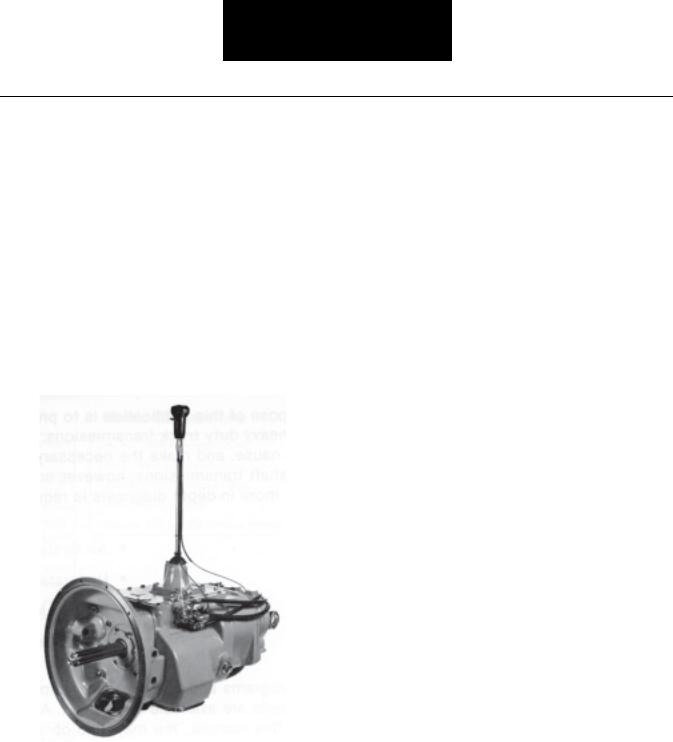
TRANSMISSION FUNCTION
The transmission must efficiently transfer the engine’s power, in terms of torque, to the vehicle’s rear wheels. Torque is the twisting or circular force delivered by the engine’s flywheel.
The transmission’s gear ratios increase or decrease torque depending on the requirements needed to move or start the load. Gearing also increases or decreases speed. The gear ratios are correctly spaced so that the engine will operate in its most efficient RPM range with progressive speed changes.
To meet the vehicle’s requirements, the transmission must have ratios low enough to start the vehicle moving, to maintain movement up grades, and to keep engine operating in its peak efficiency range. The transmission, too, must provide an easy method for gear selection.
2
Transmission Function
COUNTERSHAFT |
MAINSHAFT |
OUTPUT |
|
GEAR |
SHAFT |
||
DRIVE GEAR |
|||
|
|
|
MAINSHAFT |
|
Transmission |
|
|
Function |
|
INPUT SHAFT |
COUNTERSHAFT |
GEAR |
|
|
|
SLIDING |
|
|
|
CLUTCH |
|
AND DRIVE GEAR |
DRIVE GEAR |
|
|
|
|
|
|
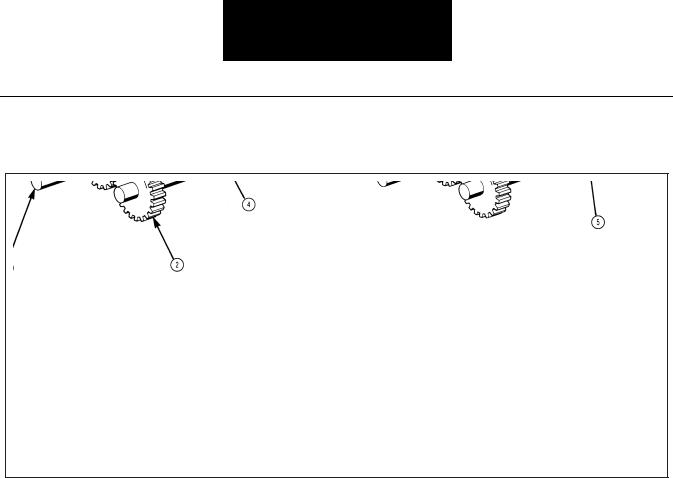
A simplified diagram of the power flow through a Fuller twin countershaft transmission will help show how torque and speed are changed, and how torque is divided between the two countershafts.
The input shaft and drive gear (1) are in constant mesh with both countershaft drive gears (2); when the input shaft turns, the countershaft gears are in constant mesh with the “floating” mainshaft gears (3). The mainshaft gears are simply free-wheeling on the mainshaft (4). A sliding clutch gear (5), which is splined to the mainshaft, is engaged into the internal clutching teeth of the mainshaft gear, coupling it to the mainshaft. The mainshaft will now be turning at the selected gear ratio.
Fuller twin countershaft Roadranger® transmissions commonly consist of a five speed front section and either a two or three speed auxiliary section, both in one case.
3

Power Flow
POWER FLOW
1.Power (torque) from the engine flywheel is transferred to the input shaft.
2.Splines on input shaft engage internal splines in hub of drive gear.
3.Torque is split between the two countershaft drive gears.
4.Torque delivered by two countershaft gears to mainshaft gear which is engaged. Diagram shows first speed gear engaged.
5.Internal splines in hub of mainshaft gear transfers torque to mainshaft through sliding clutch gear.
6.Mainshaft transfers torque to auxiliary drive gear through a self-aligning coupling gear located in hub of auxiliary drive gear.
7.Torque is split between the two auxiliary countershaft drive gears. (In direct drive or high range, power is delivered to the output shaft from the auxiliary drive gear through a self-aligning sliding clutch gear.)
8.Torque is delivered by the two countershaft low range gears to the low range gear.
9.Torque delivered to output shaft through selfaligning sliding clutch gear.
10.Output shaft is attached to driveline.
4

Timing
TIMING
All Fuller twin countershaft transmissions are “timed” at assembly. It is important that proper timing procedures are followed when reassembling the transmission. Timing assures that the countershaft gears will contact the mating mainshaft gears at the same time, allowing mainshaft gears to center on the mainshaft and equally divide the load.
One set of gears must be timed in the front section, and one set the auxiliary section. Timing consists of marking the proper teeth before installation and meshing the marked teeth during assembly. The following is step by step procedure for timing.
Front Section
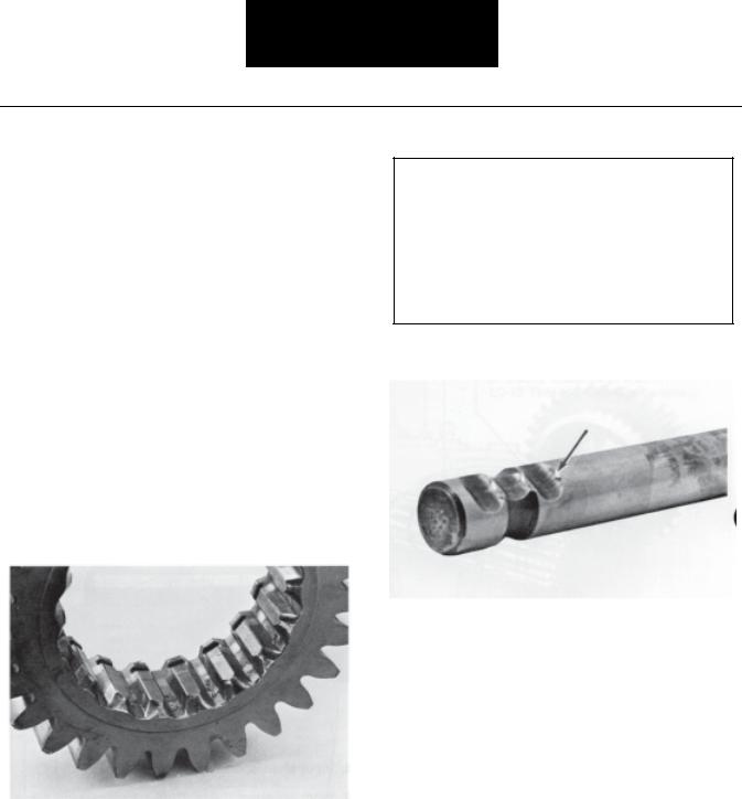
Drive gear teeth correctly marked for timing.
Cut 7300G-11/86
1.Main Drive Gear – Mark any two adjacent teeth on the drive gear, then mark the two adjacent teeth which are directly opposite the first set marked. There must be an equal number of teeth between the markings on each side of the gear.
Tooth on countershaft directly over keyway marked for timing.
Cut 7300H-11/86
2.Countershaft Drive Gears – Mark on each drive gear the gear tooth which is directly over the keyway. This tooth is stamped with an “O” for identification.
Countershaft gear teeth meshed with drive gear
teeth for correct timing.
Cut 7300F-11/86
3.Meshing Countershaft Gears and Main Drive Gear – Install the drive gear assembly. Mesh the marked left countershaft gear tooth between the two marked teeth on the drive gear. Repeat the procedure with right countershaft.
Auxiliary Section
The gear set which is marked for timing in the auxiliary section varies, depending on the model. Usually the gear at the rear of the auxiliary is used.
1.Mainshaft Gear – Mark any two adjacent teeth on the mainshaft gear, then mark the two adjacent teeth directly opposite.
2.Countershaft Gears – On each countershaft assembly mark the gear tooth which is stamped with “O”.
Note: Refer to the appropriate service manual for more detailed timing instructions for the Fuller twin countershaft transmission being assembled.
Timing
5

Common Transmission Complaints
COMMON TRANSMISSION COMPLAINTS
Vibration
Although the effects of vibration will show up in the transmission, vibration usually originates somewhere else in the drive train. Vibration can usually be felt or heard by the driver; however, in some cases, transmission damage caused by vibration will occur without the driver’s knowledge. (Refer to the “Torsional Vibration” section for the causes and cures of vibration problems.)
Some Transmission Problems Due to Drive Train Vibration:
1.Gear rattle at idle. (See “Shafts” section.)
Fretted Splines
2.Gear and shaft splines “fretted”.
3.Noise. (See “Noise” section.)
4.Fretted bearings. (See “Bearing” section.)
5.Repeated rear seal leakage. Broken synchronizer pins.
Broken Synchronizer Pins
6.Broken or loose synchronizer pins.
7.Continuous loosening of capscrews, brackets and mountings.
Input Spline Wear
8.Worn shaft spline wear.
9.Worn universal joints. (Not a transmission symptom, but an indicator of vibration.)
6
Common Transmission Complaints
Common causes of vibration:
1.Driveline imbalance or misalignment. (See “Transmission Alignment” section.)
2.Unbalanced wheels or brake drums.
3.Rough running engine.
4.Broken or worn engine mounts.
5.Worn suspension.
Gear Slipout and Jumpout
Front Section
When a sliding clutch is moved to engage with a mainshaft gear, the mating teeth must be parallel. Tapered or worn clutching teeth will try to “walk” apart as the gears rotate. Under the right conditions, slipout will result. Some of these conditions are:
1.Transmission mounted eccentrically with engine flywheel pilot.
2.Excessive gear clashing which shortens clutching teeth.
Snubbed Clutching Teeth
3.Gear clutching teeth wearing to a taper.
Detent
Spring
Cut 7233A-11/86
4.Insufficient pressure on detent ball from weak or broken detent spring.
Worn Yoke Bar
5.Excessive wear on detent notch of yoke bar.
6.Incorrect adjustment of remote shift control linkage resulting in partial engagement. Also check for loose connections and worn bushings.
Slipout will generally occur when pulling with full power or decelerating with the load pushing.
Jumpout will occur when a force sufficient to overcome the detent spring pressure is applied to the yoke bar, moving the clutch gear to a neutral position.
Complaints |
Transmission Common |
|
|
7

Common Transmission Complaints
Conditions Which May Produce Jumpout
Cut 8005-11/88
1.Extra heavy and long shift levers which swing, pendulum fashion, from operating over uneven terrain. Whipping action of the lever overcomes detent spring tension.
2.Mechanical remote controls with the master mounted to the frame. Relative movement between engine-transmission package and frame can force transmission out of gear. Worn or broken engine mounts increase the effects of this condition.
Auxiliary Section
Slipout in the auxiliary section may be caused by the clutching teeth being worn, tapered, or not fully engaged. These conditions cause the clutch gear to “walk” out of engagement as the gears turn. Causes of these types of clutching defects are clashing or normal wear after long life. Vibrations set up by an improperly aligned driveline and low air pressure add to the slipout problem.
Tapered Clutching Teeth
Jumpout in the auxiliary section usually occurs with the splitter gear set. If torque is not sufficiently broken during splitter shifts, the sliding clutch gear may not have enough time to complete the shift before torque is reapplied to the gears. As torque is reapplied, the partially engaged clutch gear “jumps” out of the splitter gear. Since the gears have torque applied to them, damage will be done to the clutching teeth of the mating gears.
Hard Shifting
The effort required to move a gear shift lever from one gear position to another varies. If too great an effort is required it will be a constant cause of complaint from the driver.
Most complaints are with remote type linkages used in cab- over-engine vehicles. Before checking the transmission for hard shifting the remote linkage should be inspected. Linkage problems stem from worn connections or bushings, binding, improper adjustment, lack of lubrication on the joints or an obstruction which restricts free movement.
To determine if the transmission itself is the cause of hard shifting, remove the shift lever or linkage from the top of the transmission. Then, move the shift blocks into each gear position using a pry bar or screwdriver. If the yoke bars slide easily, the trouble is with the linkage assembly. If the trouble is in the transmission, it will generally be caused by one of the following:
1.Splines of sliding clutch gear binding on mainshaft as a result of a twisted mainshaft key, bent shift yoke or bowed mainshaft key.
2.Yoke bars binding in the bar housing as a result of cracked housing, over-torqued shift block lockscrew, sprung yoke bar, or swelled areas of the yoke bar.
8
Common Transmission Complaints
If hard shifting occurs only in first and reverse, the shift block detent plunger movement may be restricted. This can result from burrs on the plunger, or from overtightening the plunger spring plug. With the plunger blocked in the depressed position, the plug should be tightened until it bottoms out against the spring, then backed out 1/4 to 1/2 turn.
Gear clashing should not be confused with hard shifting. Gear clashing occurs when an attempt is made to engage the clutch gear before it has reached synchronization with the mainshaft gear. (See “Clashing”, this section.)
Heat
The transmission operating temperature should never exceed 250°F (120°C) for an extended period of time. If it does, the oil will breakdown and shorten transmission life.
Because of the friction of moving parts, transmissions will produce a certain amount of heat. In most cases normal operating temperature is approximately 100°F (40°C) above ambient. Heat is dissipated through the transmission case. When conditions prevent the proper dissipation of heat, then overheating occurs.
Before checking for possible causes of overheating, the oil temperature gauge and sending unit should be inspected to make sure they are giving correct readings.
Causes of Overheating (See also “Lubrication”)
1.Improper lubrication. Oil level too low or too high, wrong type of oil, or an operating angle of more than 12 degrees.
2.Operating consistently under 20 MPH.
3.High engine RPM.
4.Restricted air flow around transmission, due to transmission being “boxed in” by frame rails, deck lids, fuel tanks and mounting brackets, or by a large bumper assembly.
5.Exhaust system too close to transmission.
6.High ambient temperature.
7.High horsepower, overdrive operation.
8.Coasting downhill with the clutch depressed.
In some cases an external oil cooler kit can be used to correct overheating problems.
Transmission Oil Coolers are:
Recommended
-With engines of 350 H.P. and above with overdrive transmissions
Required
-With engines 399 H.P and above with overdrive transmissions and GCWs over 90,000 lbs.
-With engines 399 H.P. and above and 1400 Lbs.-Ft. or greater torque
-With engines 450 H.P. and above
Noise
There will always be a certain level of noise due to normal transmission operation. However, excessive noise, or unusual noise such as whine, growl, or squeal indicates some kind of a problem.
The transmission itself can be the cause of excessive or unusual noise. Also noise can originate elsewhere in the vehicle, but be picked up and amplified by the transmission.
Transmission Noise
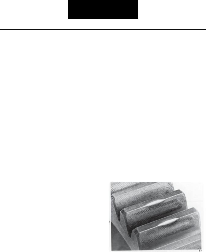
1.Knocking or Thudding
a.Gears – Bumps or swells on gear teeth. Such bumps or swells can be removed with a hone or small hand grinder; these areas can be identified as highly polished spots on the face of the gear tooth. Generally, this noise is more prominent when the gear is loaded; thus, the problem gear can be located as the noise occurs in a specific gear position. Bumps or swells are caused by
Complaints |
Transmission Common |
|
|
9
Loading...