


 Loading...
Troubleshooting Guide
Lightning Series
TRTS0580
January 2008
FRLO-14410C-T2
FRLO-15410C
FRLO-15410C-T2
FRLO-16410C
FRLO-16410C-T2
FRLOF-14410C
FRLOF-14410C-T2
FRLOF-15410C
FRLOF-15410C-T2
FRLOF-16410C
FRLOF-16410C-T2

For parts or service call us Pro Gear & Transmission, Inc.
1(877) 776-4600
(407)872-1901 parts@eprogear.com
906 W. Gore St. Orlando, FL 32805

General Warnings
General Warnings
Before starting a vehicle:
1.Sit in driver’s seat
2.Place shift lever in neutral
3.Set the parking brake
Before working on a vehicle or leaving the cab with engine running:
1.Place shift lever in neutral
2.Set parking brake
3.Block wheels
Do not release the parking brake or attempt to select a gear until the air pressure is at the correct level.
When parking the vehicle or leaving the cab:
1.Place shift lever in neutral
2.Set the parking brake
Do not operate if alternator lamp is lit or if gauges indicate low voltage.
Suggested Tools
•Volt/Ohm Meter
SPX / Kent-Moore 1 (800) 328-6657 P/N 5505027
•PC-based Service Tool “ServiceRanger” Contact your OEM
•Data Link Tester
Eaton Service Parts 1 (800) 826-4357 P/N MF-KIT-04
•Eaton Test Adapter Kit
SPX / Kent-Moore 1 (800) 328-6657 P/N J-43318
•6-Pin Deutsch Diagnostic Adapter SPX / Kent-Moore 1 (800) 328-6657 P/N J-38500-60A
Related Publications
•TRIG-0580 - Lightning Installation Guide
•TRDR-0580 - Lightning Driver Instructions
•TRSM-0580 - Lightning Service Manual
For more information call 1-800-826-HELP (4357) or visit www.Roadranger.com.

Table of Contents
Section 1: Basic Troubleshooting
Diagnostic Procedure for Lightning Models ............. |
1-2 |
Operational Check List ............................................. |
1-3 |
Basic System Troubleshooting ................................. |
1-4 |
What To Do If The Transmission |
|
Is Not Operating Properly ................................ |
1-5 |
Retrieving Fault Information ..................................... |
1-6 |
Fault Code Table for Lightning Transmission ........... |
1-7 |
Symptom Complaints ............................................... |
1-8 |
Air System Troubleshooting
Vehicle Air Supply Requirement ............................. |
1-12 |
Air System - Overview ............................................ |
1-13 |
Air System - ECU ................................................... |
1-14 |
Air System - Splitter Subsystem ............................ |
1-15 |
Air System - Range Subsystem .............................. |
1-16 |
Clutch Housing Breather Leak Overview ................ |
1-18 |
Clutch Housing Breather Leak ................................ |
1-19 |
Transmission ECU Breather Leak Overview ............ |
1-20 |
Transmission ECU Breather Leak ........................... |
1-21 |
Range Cylinder Test Overview ................................ |
1-22 |
Range Cylinder Test ............................................... |
1-23 |
Splitter Cylinder Test Overview .............................. |
1-26 |
Splitter Cylinder Test .............................................. |
1-27 |
Electronic System Troubleshooting
Electrical System Requirements ............................. |
1-30 |
Wiring Diagram ...................................................... |
1-31 |
Pinouts ................................................................... |
1-32 |
Power-Up Sequence Test Overview ....................... |
1-34 |
Power-up Sequence Test ....................................... |
1-35 |
Electrical Pretest Overview ..................................... |
1-38 |
Electrical Pretest .................................................... |
1-39 |
Shift Knob TestNo Fault Codes Overview ............. |
1-42 |
Shift Knob TestNo Fault Codes ............................ |
1-43 |
J-1587 Data Link Test Overview ............................. |
1-46 |
J-1587 Data Link Test ............................................ |
1-47 |
Section 2: Fault Isolation Procedures
Component Code 11(SID 254, FMI 12) |
|
Transmission ECU ............................................ |
2-1 |
Component Code 33 (PID 158 or 168, FMI 3 or 4) |
|
System Voltage Fault ........................................ |
2-3 |
Component Code 35 (SID 231, FMI 2) |
|
J-1939 Data Link Test ...................................... |
2-5 |
Component Code 36 (SID 48 or 49, FMI 2) |
|
Position Sensor Test ...................................... |
2-13 |
Component Code 43 (SID 36, FMI 4, 5, 6) |
|
Low Range Solenoid ...................................... |
2-15 |
Component Code 46 (SID 37, FMI 4, 5, 6) |
|
Splitter Solenoid ............................................. |
2-17 |
Component Code 48 (SID 35, FMI 4, 5, 6) |
|
High Range Solenoid ...................................... |
2-19 |
Component Code 58 (PID 191, FMI 2) |
|
Output Shaft Speed Sensor ............................ |
2-21 |
System Code 66 (SID 58, FMI 1) |
|
Unconfirmed Torque Path .............................. |
2-25 |
System Code 71 (SID 61, FMI 7) |
|
Range or Splitter Stuck in Gear ...................... |
2-29 |
Component Code 73 (SID 58, FMI 11) |
|
Transmission Missed Synchronous ............... |
2-31 |
System Code 74 (SID 14, FMI 7) |
|
Engine Missed Synchronous .......................... |
2-33 |
System Code 93 (SID 231, FMI 14) |
|
J-1939 Engine Message Fault ......................... |
2-33 |
Reverse Switch Test Overview ............................... |
2-39 |
Reverse Switch Test .............................................. |
2-40 |
Neutral Switch Test Overview ................................ |
2-43 |
Neutral Switch Test ................................................ |
2-44 |
Contents of Table
1-1

Fault Isolation Procedures
Diagnostic Procedure for Lightning Models
Key On
Service light |
No |
- Perform vehicle electrical test |
comes on for a |
||
few seconds |
|
- Perform "No service light test" |
then turns off |
|
- Solid service light? - Replace ECU |
|
|
Yes
Retrieve active fault codes
Yes |
- Perform vehicle electrical test |
- Follow troubleshooting guide |
|
Active Codes? |
diagnostics for all Actives Codes |
|
- Clear Inactive Codes/test drive & |
|
confirm code(s) have not reset |
No |
|
(Code 25) |
|
Retrieve inactive |
|
fault codes |
|
Inactive
Codes?
No
(Code 25)
|
- Record & clear inactive fault codes |
Yes |
- Verify complaints / test drive |
- If fault code is reset after clearing, |
|
|
perform vehicle electrical test, and |
|
|
|
following diagnostics for symptom |
|
driven faults |
Yes |
- Perform vehicle electrical test |
- Perform pneumatic test |
|
Symptom? |
- Isolate transmission / clutch issues |
|
- Follow basic troubleshooting/symptom |
|
driven diagnostic procedures |
No |
|
Test Complete |
|
1-2

Fault Isolation Procedures
Operational Check List
When operating properly, the lightning transmission will act in the following manner: |
|
||
• |
Top-2 feature will not function with cruise control turned off. |
|
|
• |
Service light flashes once at vehicle initial power up. |
|
|
• |
Service light flickers at vehicle power down. |
|
|
• |
Service light flashes continuously with an active fault code. |
|
|
• |
Synchronizer will not trigger with key off. |
|
|
• |
Synchronizer will not trigger in neutral with key on and vehicle stationary. |
|
|
• |
Synchronizer will trigger with key on, vehicle stationary and lever moved into a high range gear. |
|
|
• |
Synchronizer will not downshift into low range if lever is moved into a low range gear at too high of road speed. |
|
|
• |
If started in a high range gear the vehicle accelerator pedal will be “dead”. |
|
|
• |
If driver beats the range up-shift with lever movement to a high range gear the accelerator pedal is “dead” until synchro- |
|
|
|
nous is made. |
|
|
• |
Splitter will not trigger with key off. |
|
|
Fault |
|||
• |
Splitter will trigger with key on and in any lever position. |
||
• |
Engine accelerates when splitter downshifts if the driver doesn’t control engine RPM for proper synchronous. |
Isolation |
|
• |
Accelerator pedal is “dead” when splitter is up shifting if the driver attempts to accelerate before splitter synchronous is |
|
|
|
made. |
Procedures |
|
• |
Aggressive splitter shifts below 1100 engine RPMs and whenever the transmission has a fast deceleration of the output |
||
|
|||
|
shaft. |
|
|
• |
Aggressive splitter shifts with clutch disengaged or foot resting on clutch pedal disengaging clutch switch. |
|
|
• |
Aggressive splitter shifts with clutch switch wired improperly – check for engine brake and cruise control functionality. |
|
|
1-3

Fault Isolation Procedures
Basic System Troubleshooting
Following is information to help a vehicle operator start basic troubleshooting of the transmission system.This is not a complete list. In many cases, the vehicle needs to be evaluated by a trained and experienced transmission technician.
Problem |
Possible Causes |
|
|
|
|
Growl/Rattle in a “float” or |
Check for damaged, worn, or defective driveshaft, support bearing, or u-joints, which would result |
coast condition. |
in noise or vibration. Check for improper vehicle ride height, which would cause improper u-joint |
|
operating angles. Check for axle problem, which would result in noise or vibration. Check for tire |
|
problem, which would result in noise or vibration. |
|
|
At idle |
Check for damaged or defective master clutch, master clutch release bearing, or clutch linkage, |
|
which would result in noise or vibration. Check for loose components, brackets, exhaust system, |
|
and hoses in transmission area, which would result in noise or vibration. |
|
|
Growl/Rattle on a “pull” |
Check for engine problem, which would result in noise or excessive vibration.Check master clutch |
|
for defects in dampening devices. |
|
|
Lever |
Check for loose or damaged shift lever, which may vibrate and cause noise. Check for components |
|
added to the shift lever; such as, cruise control, which may vibrate and cause noise. |
|
|
All other conditions |
Check for loose clutch housing bolts. Check transmission oil for excessive metal particles, which |
|
may indicate internal problem. Check for damaged or worn gearing. |
|
|
Problem |
Possible Causes |
|
|
|
|
Hard Lever Shifting |
Check for damaged or binding shift lever or shift control system.Check for lever interference with |
|
cab floor. Check for upper or lower shift boot tugging on shift lever. Check for a defective or dam- |
|
aged master clutch, which would result in clutch drag. Check for improper clutch brake engage- |
|
ment. Check that proper shifting procedures are followed. |
|
|
Problem |
Possible Cause |
|
|
|
|
Transmission is operating |
If transmission is equipped with an internal cooler, check for pinched engine coolant hoses or |
at higher than normal tem- |
closed shut off valves. See section on Operating Temperatures with Coolers. Check oil level. |
perature |
|
|
|
1-4

Fault Isolation Procedures
What to Do if the Transmission is Not Operating Properly
If a problem occurs with the transmission or vehicle system, the transmission may not shift correctly. These effects may include:
•Harsh, slow, or grinding button only shifts.
•No button shifts (5 gear ratios only).
•No range shift (low range or high range gear ratios only).
The Service Light on the Shift Knob may be on continuously, may be flashing, or may not illuminate at all.
If the Transmission is Not Operating Properly, Try the Following Steps:
1.Check the dash air gauge to make sure at least 90 PSI is available in both primary and secondary air systems.
2.Try resetting the Transmission Electronic Control Unit (ECU) - See procedure below.
3.If vehicle and road conditions permit, you may be able to operate the transmission as a 5 speed (no button shifts).
Transmission Reset Procedure
In some cases, “resetting” the transmission Electronic Control Unit (ECU) can restore proper transmission operation. Use the following procedure to reset the ECU.
•When it is safe to do so, stop the vehicle.
•Place the transmission shift lever in neutral and turn the ignition key to the “off” position.
•Wait 5 seconds.
•Restart the engine.
•If the problem continues, proceed to page 9 and identify the symptom.
Transmission Diagnostics
The Lightning Series Transmission ECU has self-diagnostic capability. The transmission recognizes when a problem occurs and “stores” the information about these problems (faults) in the ECU memory. This information can be retrieved by the following methods:
•Retrieve basic fault information (flash codes) by counting flashes of the service light.
•Some OEM vehicles have an electronic dashboard, which displays fault information. Refer to the specific OEM chassis operator instructions for the procedure.
•Connect an applicable hand-held or PC diagnostic tool to the vehicle’s SAE J-1587 diagnostic connector.
Procedures Isolation Fault
1-5
Fault Isolation Procedures
Retrieving Fault Information
The transmission Electronic Control Unit (ECU) turns on the service lamp, located on the shift knob, in the event the ECU detects an electronic fault and at initial power-up. Once the ECU has successfully powered-up, the ECU turns off the service lamp. The power-up sequence usually takes a few seconds. The service lamp remains on continuously if the ECU execution malfunctioned at power-up. The ECU begins code diagnostics only after the ECU has successfully powered-up. The service lamp flashes steadily if the ECU has detected an Active fault code.
Note: Any Active code detected at vehicle start-up immediately starts flashing the service light on the shift knob.
The service light provides access to diagnostic fault information, which has been logged in the transmission ECU. The service light flashes a sequence of on/off pulses, which can be translated into specific “flash codes”. The flash codes can then be used to identify a specific fault in the transmission system.
Transmission faults are classified as either Active (current problem) or In-Active (non-current problem). An Active fault is logged when the ECU recognizes a problem with the transmission. During an Active fault, the service light flashes steadily or may stay on continuously. If during vehicle operation, the problem corrects itself, the service light stops flashing and the fault is logged as an In-Active fault.
How to Retrieve Fault Codes
Retrieve Lightning fault codes by enabling the Lightning system’s self-diagnostic mode.
Note: You can also use a P.C. based diagnostic tool such as ServiceRanger to retrieve fault codes.
Retrieving Active Fault Codes:
1.Place the shift lever in neutral.
2.Set the parking brakes.
3.Turn the ignition key on but do not start the engine.
4.Starting with the key in the on position. Turn the key off and on two (2) times within five seconds ending with the key in the on position.
5.Observe the flash sequence of the service light on the shift knob. Flash codes may take 5 seconds to begin flashing. A one or two second pause separates each stored code, and the sequence automatically repeats itself after flashing all codes.
Retrieving In-Active Fault Codes:
1.Use the procedure to retrieve Active fault codes except, turn the key off and on four (4) times within five seconds ending with the key in the on position.
2.Observe the flash sequence of the service light on the shift knob. A one or two second pause separates each stored code, and the sequence automatically repeats itself after flashing all codes.
Clearing Fault Codes:
The following procedure clears all In-Active fault codes from the ECU’s memory.
1.Place the shift lever in neutral.
2.Set the parking brakes.
3.Turn the ignition key on but do not start the engine.
4.Start with the key in the on position. Turn the key off and on six (6) times within five seconds ending with the key in the on position. The service light will flash on for 5 seconds confirming the codes are cleared.
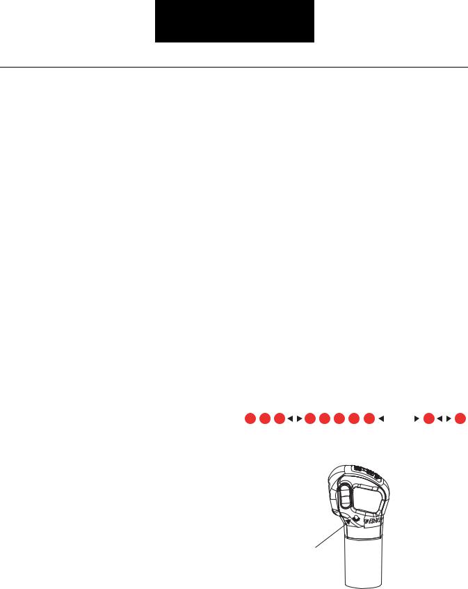
Example of Flash Codes
Fault Code 35 |
|
|
Fault Code 11 |
|||||||||
|
|
|
|
|
|
|
|
|
|
|
|
|
|
|
|
|
|
|
|
|
|
|
|
|
|
|
|
|
|
|
|
|
|
|
|
|||
|
|
|
|
|
|
|
|
|
|
|
||
Short Pause |
Long Pause |
|
Short Pause |
|||||||||
Service Light
1-6

Fault Isolation Procedures
Fault Code Table for Lightning Transmission
Component Fault Codes*
Flash |
Description |
MID |
PID |
SID |
FMI |
Code |
|
|
|
|
|
|
|
|
|
|
|
|
|
|
|
|
|
11 |
Transmission ECU |
130 |
|
254 |
12 |
25 |
No Codes |
130 |
|
|
|
33 |
Ignition/Battery Voltage Low or High |
130 |
158 or 168 |
|
3 or 4 |
35 |
Engine to Transmission J1939 |
130 |
|
231 |
2 |
|
Communication Link |
|
|
|
|
36 |
Shift Lever Position Sensor |
130 |
|
48 or 49 |
2 |
43 |
Low Range Shift Solenoid |
130 |
|
36 |
4, 5, or 6 |
46 |
Splitter Shift Solenoid |
130 |
|
37 |
4, 5, or 6 |
48 |
High Range Shift Solenoid |
130 |
|
35 |
4, 5, or 6 |
58 |
Output Speed Sensor |
130 |
191 |
|
2 |
|
|
|
|
|
|
System Fault Codes **
Flash Code |
Description |
MID |
PID |
SID |
FMI |
|
|
|
|
|
|
|
|
|
|
|
|
66 |
Unconfirmed Torque Path (Input speed and |
130 |
|
58 |
1 |
|
output speed do not equal known gear ratio) |
|
|
|
|
71 |
Splitter or Range Stuck in Gear |
130 |
|
61 |
7 |
73 |
Transmission Missed Synchronization |
130 |
|
58 |
11 |
74 |
Engine/Transmission Missed |
130 |
|
14 |
7 |
|
Synchronization |
|
|
|
|
93 |
J-1939 Engine Message Fault |
130 |
|
231 |
14 |
|
|
|
|
|
|
*Component Fault Codes specifically isolate problems that may arise with the electronic components used in the Lightning series transmissions. These codes occur at initial vehicle power-up if not induced by intermittent vibration or heat problems.
**System Fault Codes specifically isolate problems that may arise from a mechanical or pneumatic problem that has prevented or missed a shift in the Lightning transmission. System fault codes are only active during vehicle operation and are not detected at initial vehicle power-up.
Note: System fault codes also indicate problems with other components that affect the performance of the transmission such as low air pressure. Troubleshoot the code properly to isolate the component causing the fault to become active.
# Hand Held Codes
MID – Message ID Assignment. In this case, MID 130 represents the transmission.
PID – Parameter ID Assignment. Generally represents a status or value.
SID – Subsystem ID Assignment. Identifies a failure in a subsystem.
FMI – Failure Mode ID. Describes the type of failure detected in the subsystem
Procedures Isolation Fault
1-7
Fault Isolation Procedures
Symptom Complaints
Symptom |
Possible Condition |
Remedy |
|
Reference |
|
|
|
|
|
No service light |
Electrical circuit is open, |
No fault codes set. Performance of |
|
|
|
grounded, or blown VIGN fuse |
transmission not affected by non- |
|
|
|
or faulty light |
functioning light. Check fuse then if |
|
|
|
|
necessary, perform service |
light |
|
|
|
test. |
|
|
|
|
|
|
|
Service light on continuously |
Light circuit grounded to VBATT, |
Repair vehicle wiring harness. |
|
|
|
transmission performance not |
|
|
|
|
affected |
|
|
|
|
|
|
|
|
|
Transmission ECU internal fail- |
Perform vehicle electrical test, if OK |
|
|
|
ure; |
- replace transmission ECU. |
|
|
|
3 speed operation only; |
|
|
|
|
No splitter or range shifts |
|
|
|
|
|
|
|
|
Top 2 option not functioning |
Cruise control turned off |
Turn on cruise control. |
|
|
|
|
|
|
|
|
Top 2 option stops functioning |
Repair for other faults such as Out- |
|
|
|
as a result of another problem |
put Speed Sensor Position Sensor. |
|
|
|
|
Look for other complaints such as |
|
|
|
|
engine brake or cruise not function- |
|
|
|
|
ing. |
|
|
|
|
|
|
|
No button shifts after cruise con- |
Hold Mode |
Normal Operation. Lever must be |
|
|
trol if turned off while in Top 2 |
|
cycled through neutral to regain but- |
|
|
mode |
|
ton function. |
|
|
|
|
|
|
|
Harsh or aggressive splitter shifts |
ECU Malfunction |
Active Fault Code 11. |
|
page 1 |
|
|
|
|
|
Before proceeding, see note at |
Position Sensor Malfunction |
Active Fault Code 36. |
|
page 13 |
bottom of page. |
|
|
|
|
|
|
|
|
|
(any shift using the splitter button) |
Engine Missed Synchronization |
Active Fault Code 74. |
|
page 33 |
|
|
|
|
|
Grinding or Raking Splitter Shifts |
Out-Of-Synchronous or shifts |
Lever/Splitter shifts attempted in an |
|
|
|
Engine Synchronous speed out- |
out-of-synchronous condition. Re- |
|
|
|
of-limit of operating range |
view Driver Instruction Book - |
|
|
|
|
TRDR-0580 - for proper driving |
|
|
|
|
techniques. |
|
|
|
|
|
|
|
(Shifts from 1st to 2nd, 3rd. to 4 |
Low or high air pressure |
Faulty Air Regulator. |
|
|
th, 5th to 6th, 7 th to 8 th, and 9 th |
|
|
|
|
to 10th. Shift grinds but engages.) |
|
|
|
|
|
|
|
|
|
|
Splitter leak or partial blocked air |
Perform Splitter Cylinder Test. |
|
page 26 |
|
system |
|
|
|
|
|
|
|
|
|
Driver resting foot on Clutch |
Remove foot from clutch pedal ex- |
|
|
|
Pedal so as to disengage clutch |
cept when necessary to shift, start or |
|
|
|
switch but still has clutch en- |
stop the vehicle. |
|
|
|
gaged |
|
|
|
|
|
|
|
|
1-8

Fault Isolation Procedures
Symptom |
Possible Condition |
Remedy |
|
Reference |
|
|
|
|
|
|
Clutch Switch Contamination |
Cruise control and engine brake is |
|
|
|
built up on switch, for example, |
also inoperative when the clutch |
|
|
|
dirt, ice, etc. or Mechanical |
switch malfunctions. Refer to OEM |
|
|
|
Clutch Linkage |
manual for |
troubleshooting clutch |
|
|
|
switch. |
|
|
|
|
|
|
|
Note: Aggressive splitter shifts may occur normally under the following conditions.
1.Low speed splitter shifts below 1100 RPMs. - This is normal operation.
2.Splitter shifts on grades with heavily loaded vehicle. - This is normal operation.
3.Anytime the vehicle has a fast deceleration of the transmission output shaft. For example, making a hard left-hand turn and moving the splitter at the same time. - This is normal operation.
Symptom |
Possible Condition |
Remedy |
Reference |
|
|
|
|
|
|
|
|
Harsh shifts (Lever Only) |
Out-Of-Synchronous Shifts |
Lever shifts attempted in an out-of- |
|
|
|
|
|
synchronous condition. Review Driv- |
|
|
|
|
|
|
|
Fault |
|
|
|
er’s Instruction Book for proper tech- |
|
|
|
|
|
|
|
|
|
|
|
niques. |
|
|
|
(Skip shifts. i.e. 1 st to 3 rd., or 3 |
|
|
|
|
Isolation |
Clutch Brake |
Check for improper clutch brake en- |
|
|
||
Clutch Drag |
Adjust Clutch and check for clutch |
|
|
|
|
rd. to 5 th.) |
|
slippage and drag. |
|
|
|
|
|
gagement. |
|
|
Procedures |
|
|
|
|
|
|
|
|
|
|
|
|
Slow/grinding/raking or inopera- |
Low or High Air Pressure |
Perform Range Cylinder Test. |
page 22 |
|
|
tive Range Shift (Shift from 6 th to |
|
|
|
|
|
7 th or from 7 th to 6 th.) |
|
|
|
|
|
|
Air System Leaks |
|
|
|
|
|
|
|
|
|
|
|
Reduced Air Flow |
|
|
|
|
|
Damaged Mechanical parts in- |
|
|
|
|
|
ternal to the transmission |
|
|
|
|
|
|
|
|
|
|
Five speed transmission. (Only |
ECU Malfunction |
Active Fault Code 11. |
page 1 |
|
|
Even or Odd Numbered Gears.) |
|
|
|
|
|
|
|
|
|
|
|
|
Unconfirmed torque path |
Active Fault Code 66. |
page 25 |
|
|
|
through transmission |
|
|
|
|
|
|
|
|
|
|
|
Splitter stuck in gear |
Active Fault Code 71. |
page 29 |
|
|
|
|
|
|
|
|
|
|
Review Air System Overview. |
page 13 |
|
|
|
|
|
|
|
|
|
|
Repair for damaged internal parts. |
|
|
|
|
|
|
|
|
|
|
Output Speed Sensor Malfunc- |
Perform Output Shaft Speed Sensor |
page 21 |
|
|
|
tion |
test. |
|
|
|
|
|
|
|
|
|
|
Splitter System Air Leak |
Perform Splitter Cylinder test. |
page 26 |
|
|
|
|
|
|
|
|
|
Shift Knob Malfunction |
No Active Fault Codes. Perform Shift |
page 42 |
|
|
|
|
Knob test. |
|
|
|
|
|
|
|
|
|
1-9

Fault Isolation Procedures
Symptom |
Possible Condition |
Remedy |
Reference |
|
|
|
|
|
Splitter Solenoid Short or Open |
Active Fault Code 46. Perform Sole- |
page 17 |
|
|
noid test. |
|
|
|
|
|
|
Loss of communication with |
Active Fault Code 35 and gears 1, 3, 5, |
page 5 |
|
engine |
7, 9. J-1939 communication link bro- |
|
|
|
ken. |
|
|
|
|
|
Six speed transmission. (Only 1st |
Range system air leak |
Perform Range Cylinder test. |
page 22 |
through 6th gears.) |
|
|
|
|
|
|
|
|
Position sensor malfunction |
Active Fault Code 36. |
page 13 |
|
|
|
|
|
Low Range Solenoid Malfunc- |
Active Fault Code 43. |
page 15 |
|
tion |
|
|
|
|
|
|
|
High Range Solenoid Malfunc- |
Active Fault Code 48. |
page 19 |
|
tion |
|
|
|
|
|
|
|
Range stuck in gear. |
Active Fault Code 71. |
page 29 |
|
|
|
|
|
Transmission missed synchro- |
Active Fault Code 73. |
page 31 |
|
nous. |
|
|
|
|
|
|
|
High Range Synchronizer Me- |
Perform Range Cylinder test prior to |
page 22 |
|
chanical Failure |
disassembly, then replace damaged |
|
|
|
synchronizer parts if required. Refer |
|
|
|
to “Synchronizer” repair strategy item |
|
|
|
TRSM-0915 (Note: after 12/31/04 this |
|
|
|
publication will be TRMT-0001) for |
|
|
|
repair details. |
|
|
|
|
|
Four Speed Transmission. (Only 7 |
Low Range Solenoid Malfunc- |
Active Fault Code 43. |
page 15 |
th through 10 th gears.) |
tion |
|
|
|
|
|
|
|
Range System Air Leak |
Perform Range Cylinder test. |
page 22 |
|
|
|
|
|
High Range Solenoid Malfunc- |
Active Fault Code 48. |
page 19 |
|
tion |
|
|
|
|
|
|
|
Range stuck in gear. |
Active Fault Code 71. |
page 29 |
|
|
|
|
|
Low Range Synchronizer Me- |
Perform air system test prior to disas- |
|
|
chanical Failure |
sembly, then replace damaged syn- |
|
|
|
chronizer parts if required. Refer to |
|
|
|
“Synchronizer” repair strategy item |
|
|
|
TRSM-0915 (Note: after 12/31/04 this |
|
|
|
publication will be TRMT-0001) for |
|
|
|
repair details. |
|
|
|
|
|
Three Speed Transmission (Only |
Low System Voltage |
Active Fault Code 33. |
page 3 |
1 st, 3 rd., 5 th gears) |
|
|
|
|
|
|
|
|
Loss of air pressure to trans- |
Check vehicle air pressure. |
|
|
mission. |
|
|
|
|
|
|
|
ECU Malfunction. |
Active Fault Code 11. |
page 1 |
|
|
|
|
|
|
Service light on continuously. Replace |
|
|
|
ECU. |
|
|
|
|
|
1-10

Fault Isolation Procedures
Symptom |
Possible Condition |
Remedy |
Reference |
|
|
|
|
|
Software download unsuccess- |
Replace ECU. |
|
|
ful |
|
|
|
|
|
|
Two Speed Transmission (only 7 |
ECU malfunction service light |
Replace ECU. |
|
th, 9 th gears) |
on continuously |
|
|
|
|
|
|
Neutral Switch |
Wheel Chair Lift / PTO etc. not |
Perform Neutral Switch Test per OEM |
|
|
operating |
recommendations. |
|
|
|
|
|
|
Engine will not crank (some ap- |
Perform Neutral Switch Test per OEM |
|
|
plications) |
recommendations. |
|
|
|
|
|
Reverse Switch |
Reverse Light / Beeper not |
Perform Reverse Switch Test per |
|
|
functioning. |
OEM recommendations. |
|
|
|
|
|
Procedures Isolation Fault
1-11

Fault Isolation Procedures
Vehicle Air Supply Requirement
The transmission filter/regulator assembly provides the inlet port for transmission supplied air. You will find the filter/regulator located at the rear of the transmission on the driver’s side of the truck. The filter/regulator assembly regulates the transmission supply to 80 PSI (551 kPa) maximum.
Filter / Regulator
Inlet Air Pressure Required |
90-130 PSI (620-896 kPa) |
|
|
Air Dryer |
Required |
|
|
Inlet Port Size |
SAE 3/8” – 18 NPT |
|
|
1-12
Fault Isolation Procedures
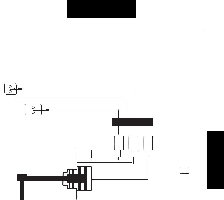
Air System - Overview
The Lightning series transmission uses an automatically controlled range cylinder to manage the air operated range shift between 6th and 7th gear. The button on the shift knob controls the splitter shift. Splitter shifts occur every time the transmission shifts consecutive from one gear to the next gear or when the button is moved from one state to the next.
The simple block diagram below shows the relationship between the air system and electronic controls.
Splitter Signal from Shift Knob
Engine Communication (J1939)
|
Diagnostic Communication (J1587) |
|
H |
|
|
L |
Non-Contacting Sensor to |
ECU |
|
sense desired range position |
|
|
|
|
|
|
|
|
|
|
|
|
|
|
|
|
|
|
|
|
|
|
|
|
|
|
|
|
|
|
|
|
|
|
|
|
|
|
|
|
|
|
|
|
|
|
|
|
|
|
|
|
|
|
|
|
|
|
|
|
|
|
|
|
|
|
|
|
|
|
|
|
|
|
|
|
|
|
|
|
|
|
|
|
|
|
|
|
|
|
|
|
|
|
|
|
|
|
|
|
|
|
|
|
|
|
|
|
|
|
|
|
|
|
Range |
|
|
|
|
|
|
H |
|
L |
S |
Solenoid |
|
|
|
|
|
|
|
|
|
|
|
|
|
|
|
|
|||||
|
|
|
|
|
|
|
|
|
|
|
|
|
|
|
Pak |
|
|
|
|
|
|
|
|
|
|
|
|
|
|
|
|
|
|
|
|
|
|
|
|
|
|
|
|
|
|
|
|
|
|
|
|
|
|
|
|
|
|
|
|
|
|
|
|
|
|
|
|
|
|
|
|
|
|
|
|
|
|
|
|
|
|
|
|
|
|
|
|
|
|
|
|
|
|
|
|
|
|
|
|
|
|
|
|
|
|
|
|
|
Charge Air |
Splitter |
Output Speed |
Sensor |
Constant Air
The Lightning series transmission utilizes an electric over air concept for actuating the splitter and range cylinders. An electric signal is sent to the ECU. The ECU then, enables a solenoid valve, which in turn directs air to the appropriate cylinder. A switch in the shift knob directs the splitter shift. The position of the switch indicates to the ECU the desired splitter state. The ECU makes the shift automatically when the proper conditions are achieved. The signal to the ECU for a range shift is automatically made when the shift lever passes from the middle rail (6th gear) to the outside rail (7th gear). A sensor detects the movement and signals the ECU to actuate the range valve. As with the splitter shift, the range shift only occurs when a specific set of conditions is achieved.
Procedures Isolation Fault
1-13
Fault Isolation Procedures
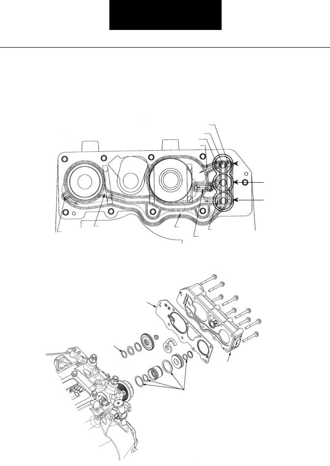
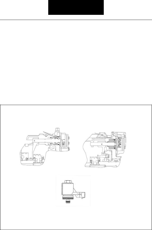
Air System - ECU
The transmission’s electronic control unit (ECU) activates solenoids in the ECU, which opens up internal air passages. The transmission air filter/regulator is the only external air system component.
The air moves through passages internal to the transmission and the seal plate of the ECU. The illustration below shows the air passages as viewed through the ECU.
Splitter Diagnostic Port
Supply to Valves
Range HI
Diagnostic Port
To HI Range
Range |
|
HI Range Valve |
Splitter
LO Range Valve
Splitter Valve
|
To Splitter |
Supply to |
From Splitter Valve |
80 PSI Supply |
Cylinder |
||
from Regulator / |
|
Valves |
To LO Range |
|
|
||
Constant Air |
|
|
|
to Splitter |
|
|
|
Seal Plate
Range Cylinder
O-ring
Electronic Control Unit
(ECU)
Splitter Cylinder
O-rings
Exploded View of Air System
1-14

Fault Isolation Procedures
Air System - Splitter Subsystem
The ECU controls the operation of the splitter solenoid function, responding to driver input from the splitter button on the shift knob or Top-2 operation.
The splitter cylinder has three distinct positions, forward (overdrive), rear (direct) and intermediate (neutral). The forward position is achieved by activating the splitter solenoid valve, which applies air pressure to the rearward side of the piston. This is the splitter state for the even numbered gears (2, 4, 6, 8 and 10)
The rearward position is achieved by de-activating the splitter solenoid valve, which exhausts the air pressure from the rearward side of the splitter piston. The constant air pressure then forces the piston rearward. This is the splitter state for the odd numbered gears (1, 3, 5, 7 and 9).
The intermediate or neutral state is achieved by the ECU rapidly turning on and off the splitter solenoid valve. This condition results in a pressure on the rearward side of the splitter piston that is between 0 and full system pressure. This neutral state is used to allow the gears to synchronize prior to engagement, thereby significantly improving the shift quality.
Constant Air Pressure |
Constant Air Pressure |
|
|
Signal Air Pressure |
Splitter in |
Splitter in |
Direct |
Neutral |
Constant Air Pressure |
|
Signal Air Pressure
Splitter in
Overdrive
Procedures Isolation Fault
1-15
Fault Isolation Procedures
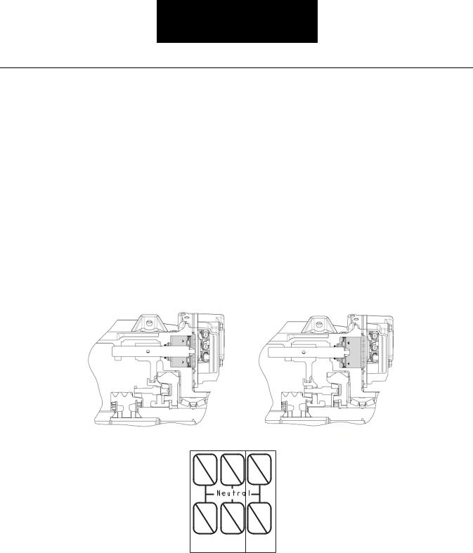
Air System - Range Subsystem
The ECU controls the operation of all range solenoid valve functions. The driver’s movement of the shift lever accomplishes a change in the position of the range from high range to low range or vice versa.
The range piston has two distinct positions. Both the forward and rearward positions are a function of mechanical stops. Only one side of the piston has air pressure at any one time. The ECU automatically selects either high or low range as the lever passes through neutral when making an up-shift from 6th gear to 7th gear or the downshift from 7th gear to 6th gear.
In either case, the distinct sound of the range shifting is audible outside the cab, standing next to the stationary truck.
Air |
Air |
|
Pressure |
||
Pressure |
||
|
Low Range
HI
R
LO
R
High Range
4 8
3 7
2 |
6 |
10 |
1 |
5 |
9 |
Low Range |
High |
|
|
|
Range |
1-16

Fault Isolation Procedures
Procedures Isolation Fault
This page left blank intentionally.
1-17
Fault Isolation Procedures
Clutch Housing Breather Leak Overview
Overview
Air leaks out the breather located on top of clutch housing.
An air operated PTO with an air leak can pressurize the transmission and cause air to leak out the transmission breather.
Required Tools
•Basic Hand Tools
Possible Causes
Detection
Audible Air Leak
Fallback
•Splitter Cylinder O-Rings
•Range Cylinder O-Ring
•Air operated PTO leak
There is no fallback mode for this failure.
Possible Leak Paths
Splitter Cylinder |
Range Cylinder |
1-18

Fault Isolation Procedures
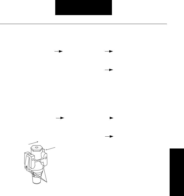
Clutch Housing Breather Leak
Step A |
Procedure |
Condition |
Action |
|
|
|
|
1. Key on.
2.Vehicle stationary and secured, air system fully charged, engine not running.
3. Listen |
for |
air |
leaking |
|
|
Air leaks in both positions |
|||
out the breather while |
|
|
|
|
|||||
moving the shift lever |
|
|
|
||||||
to make |
the |
range |
|
|
|
||||
cylinder shift from low |
|
|
|
||||||
range |
to |
high |
range. |
|
|
|
|||
When |
stationary, |
the |
|
|
|
||||
lever must be moved |
|
|
|
||||||
in and out of a high |
|
|
|
||||||
range gear to make the |
|
|
|
||||||
synchronizer shift. |
|
|
|
|
|
|
|||
Note: Oil |
leaking |
out |
|
the |
Air leaks only in low |
||||
|
breather |
may |
be a |
sign |
range |
||||
|
indicating |
an |
air |
leak |
|
||||
|
internal |
|
to |
|
the |
|
|||
|
transmission. |
|
|
|
|
|
|||
Repair the splitter cylinder, and replace all cylinder o-rings. Go to Step V.
Repair the range cylinder, and replace all cylinder o-rings. Go to Step V.
Step V |
|
Procedure |
|
Condition |
|
Action |
|
|
|
|
|
|
|
|
1. Fully |
charge air |
|
Breather still leaks |
|
Go to Step A. |
|
system on vehicle and |
|
|
|
|
|
|
check |
for |
|
|
|
|
|
effectiveness of repair. |
|
|
|
|
|
|
|
|
|
Breather does not leak |
|
Test Complete. |
Breather Housing Clutch
Leak
1-19
Fault Isolation Procedures
Transmission ECU Breather Leak
Overview
Overview
Air leaks out the breather on the ECU.
The breather exhausts a slight amount of air every time the transmission makes a range shift and when the splitter shifts to any odd numbered gear.
Detection
Audible Air Leak.
Fallback
Required Tools
•Basic Hand Tools
Possible Causes
This fault can be caused by any of the following:
•Splitter or Range Cylinder O-rings
•Solenoid Seals or O-rings (ECU)
•Seal Plate
There is no fallback mode for failure.
Possible Leak Paths |
Possible Leak Path |
|
Splitter Cylinder |
Range Cylinder |
Solenoid
(Non-Serviceable - Inside ECU)
1-20

Fault Isolation Procedures
Transmission ECU Breather Leak
Step A |
Procedure |
Condition |
Action |
|
|
|
|
1.Key on, vehicle stationary and secured, air system fully charged, engine not running.
2. Cycle |
the |
splitter |
|
Leak stops with the |
|
Replace the splitter cylinder o- |
|||||
cylinder by moving the |
|
button in the up position. |
|
rings |
and |
clean |
out |
any |
|||
button |
on |
the |
shift |
|
|
|
contamination in the cylinder. If leak |
||||
knob from |
the down |
|
|
|
continues after making this repair, |
||||||
position |
to |
the |
up |
|
|
|
then replace the transmission ECU |
||||
position. |
|
|
|
|
|
and seal plate. Go to Step V. |
|
||||
|
|
|
|
|
Leaks in either position |
|
Go to Step B. |
|
|
|
|
Step B |
Procedure |
Condition |
Action |
|
|
|
|
1.Key on, vehicle stationary and secured, air system fully charged, engine not running.
2. Cycle |
the |
|
range |
|
Leak stops when in high |
|
Replace the range cylinder piston |
cylinder by moving the |
|
range. |
|
and clean out any contamination in |
|||
shift lever |
into |
high |
|
|
|
the cylinder. If leak continues after |
|
range |
(the |
7/8 |
gear |
|
|
|
making this repair, then replace the |
position) then back into |
|
|
|
transmission ECU and seal plate. |
|||
neutral. |
|
|
The |
|
|
|
Go to Step V |
synchronizer |
makes a |
|
|
|
|
||
distinct |
audible |
noise |
|
|
|
|
|
when shifting. |
|
|
|
|
|
||
|
|
|
|
|
Leak stops when in low |
|
Replace the range cylinder piston |
|
|
|
|
|
range. |
|
and clean out any contamination in |
|
|
|
|
|
|
|
the cylinder. If leak continues after |
|
|
|
|
|
|
|
making this repair, then replace the |
|
|
|
|
|
|
|
transmission ECU and seal plate. |
|
|
|
|
|
|
|
Go to Step V. |
Step V |
|
Procedure |
|
Condition |
|
Action |
|
|
|
|
|
|
|
|
1. Charge the vehicle air |
|
No Leaks |
|
Test Complete |
|
|
system |
and test |
|
|
|
|
|
repairs |
for |
|
|
|
|
|
effectiveness. |
|
|
|
|
|
|
|
|
|
Air still leaks out breather |
|
Repeat test procedures for air leaks. |
|
|
|
|
on ECU. |
|
|
ECU Transmission
Leak Breather
1-21

Fault Isolation Procedures
Range Cylinder Test Overview
Overview
The range cylinder test does not relate to any specific fault code, but must be performed prior to disassembly of the transmission if a range system mechanical failure is suspected. The range cylinder test verifies the basic air system inputs are operating correctly, before proceeding with disassembly. The driver complaint must be confirmed or duplicated before preceding with the testing.
Detection
There is no detection process specifically for the Range Cylinder. However, failures of this type are generally detected by the driver as a symptom such as the transmission range shift may grind, rake, or fail to operate.
Fallback
Required Tools
•Basic Hand Tools
Possible Causes
This fault can be caused by any of the following:
•Truck air pressure out of range
•Faulty air/filter regulator
•Air system contamination
•Friction material worn or damaged on synchronizer
•Other internal mechanical failure
There is no fallback for the Range Cylinder Test.
1-22
Fault Isolation Procedures
Range Cylinder Test
Step A |
Procedure |
Condition |
Action |
|
|
|
|
1.Start vehicle and build up air pressure to maximum. Shut off vehicle.
Vehicle's primary and secondary air supply is less than 90 PSI or leaks down
Vehicle air pressure is greater than 90 PSI and no leaks.
Repair vehicle's air system and go to Step V.
Go to Step B.
Step B |
Procedure |
Condition |
Action |
|
|
|
|
1.Drain air tanks to prevent injury.
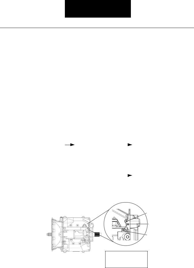
2.Remove one of three plugs in transmission filter/regulator and insert pressure gauge.
3.Start vehicle and build up air pressure to maximum. Shut off vehicle.
Front of
Transmission
Air Inlet
Port
Transmission |
filter/ |
|
Replace |
filter/regulator |
regulator pressure less |
|
assembly. Go to Step V. |
||
than or greater than 77 to |
|
|
|
|
82 PSI. |
|
|
|
|
Regulator |
pressure |
|
Go to Step C. |
|
between 77 and 82 PSI.
Regulated
Air Pressure
Filter / Regulator
Test Cylinder Range
1-23
Fault Isolation Procedures
Range Cylinder Test, continued
Step C |
Procedure |
Condition |
Action |
|
|
|
|
|
|
|
|
1.Drain air tanks to prevent injury.
2.Remove either the plug for the high range test port or low range test port located on the top of the transmission and insert pressure gauge.
3.Start vehicle and build up air pressure to maximum. Shut off vehicle.
4.Key in the on position, do not start vehicle.
5.Have an assistant move the lever to cycle the range cylinder by moving the lever in and out of a high range gear position.
6.Watch the reaction of the pressure gauge and listen for the range to shift.
Gauge |
response |
is |
|
Go to Step D. |
|
|
sudden |
and |
immediate. |
|
|
|
|
Gauge reads between 77 |
|
|
|
|||
to 82 PSI and the distinct |
|
|
|
|||
sound |
of |
the |
range |
|
|
|
shifting is audible. |
|
|
|
|
||
Gauge is slow to respond |
|
Remove transmission ECU |
and |
|||
or the range shift is not |
|
clean out any contamination in air |
||||
audible. |
|
|
|
|
passages or cylinders. Go to |
Step |
|
|
|
|
|
V. |
|
Splitter Test Port
High Range Test Port
Low Range Test Port
Clean the area around the plugs prior to removal to prevent dirt or other contamination from falling into the ports after removing the plugs.
1-24

Fault Isolation Procedures
Range Cylinder Test, continued
Step D |
Procedure |
Condition |
Action |
|
|
|
|
1.Remove and disassemble transmission.
2. Inspect |
all |
|
Synchronizer |
parts |
|
Replace damaged parts. Go to Step |
|
synchronizer parts. |
|
|
excessively |
worn |
or |
|
V. |
|
|
|
damaged. |
Refer |
to |
|
|
|
|
|
publication |
TRSM-0915 |
|
|
|
|
|
|
for |
synchronizer |
|
|
|
|
|
|
replacement guidelines. |
|
|
||
|
|
|
No parts |
worn |
or |
|
Go to Step V. |
|
|
|
damaged |
|
|
|
|
Step V |
|
Procedure |
|
Condition |
|
Action |
|
|
|
|
|
|
|
|
1. Start vehicle and road |
|
Range shifts properly |
|
Test complete |
|
|
test |
to determine |
|
|
|
|
|
repair effectiveness. |
|
|
|
|
|
|
|
|
|
Range still grinds/rakes |
|
Repeat test procedures |
|
|
|
|
or inoperative |
|
|
Test Cylinder Range
1-25

Fault Isolation Procedures
Splitter Cylinder Test Overview
Overview
The Splitter Cylinder Test does not relate to any specific fault code, but must be performed prior to disassembly of the transmission if a splitter system mechanical failure is suspected. The splitter cylinder test verifies the basic air system inputs are operating correctly, before proceeding with transmission disassembly.
Detection
There is no detection process specifically for the splitter cylinder. However, failures of this type are generally detected by the driver as a symptom such as the transmission splitter shift may grind, rake, or fail to operate. The driver complaint must be confirmed or duplicated before proceeding with the testing.
Required Tools
•Basic Hand Tools
Possible Causes
This fault can be caused by any of the following:
•Truck air pressure out of range
•Faulty air/filter regulator
•Air system contamination
•Faulty shift knob / splitter switch or vehicle wiring
•Internal mechanical failure
Fallback
There is no fallback for the Splitter Cylinder Test.
1-26
Fault Isolation Procedures
Splitter Cylinder Test
Step A |
Procedure |
Condition |
Action |
|
|
|
|
1.Review driver's instruction for proper driving technique.
2. |
Test drive truck with |
|
Driver |
operating |
splitter |
|
Provide instruction and end test. |
|
|
|
operator. |
|
improperly |
|
|
Go to Step B. |
|
|
|
|
|
Driver |
operating |
splitter |
|
|
|
|
|
|
properly |
|
|
|
|
|
|
|
|
|
|
|
|
|
Step B |
|
Procedure |
|
|
Condition |
|
Action |
|
|
|
|
|
|
|
|
|
|
1.Start vehicle and build up air pressure to maximum. Shut off vehicle.
Vehicle's primary and secondary air supplies less than 90 PSI or leaks down
Vehicle air pressure is greater than 90 PSI and no leaks
Repair vehicle's air system and go to Step V.
Go to Step C.
Step C |
Procedure |
Condition |
Action |
|
|
|
|
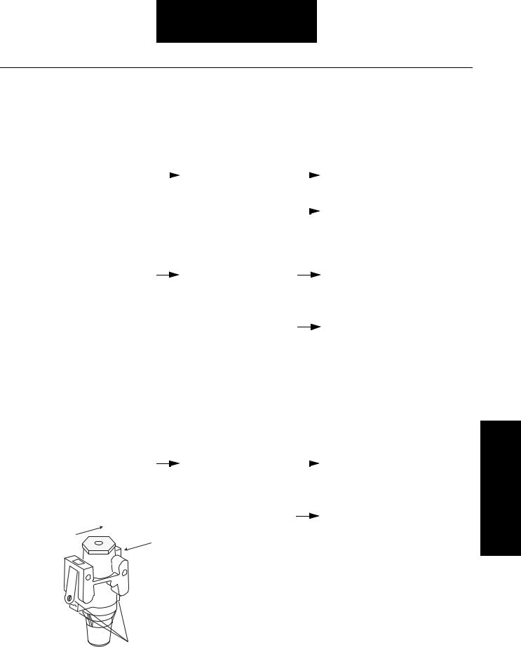
1.Drain air tanks to prevent injury.
2.Remove one of three plugs in transmission filter/regulator and insert pressure gauge.
3.Start vehicle and build up air pressure to maximum. Shut off vehicle.
Front of
Transmission
Air Inlet
Port
Transmission |
filter/ |
|
Replace filter/regulator assembly. |
regulator pressure less |
|
Go to Step V. |
|
than or greater than 77 to |
|
|
|
82 PSI |
|
|
|
Regulator |
pressure |
|
Go to Step D. |
between 77 and 82 PSI
Regulated
Air Pressure
Filter / Regulator
Test Cylinder Splitter
1-27
Loading...