


FR-14210B
Table of contents
 Loading...
Service Manual
Eaton Fuller
®
HD FR/FRO Transmissions
TRSM2400 EN-US
May 2013
FR-11210B
FR-12210B
FR-13210B
FR-14210B
FR-15210B
FR-9210B
FRF-11210B
FRF-12210B
FRF-13210B
FRF-14210B
FRF-15210B
FRF-9210B
FRO-11210B
FRO-11210C
FRO-12210B
FRO-12210C
FRO-13210B
FRO-13210C
FRO-14210B
FRO-14210C
FRO-15210B
FRO-15210C
FRO-16210B
FRO-16210C
FRO-17210C
FRO-18210C
FROF-11210B
FROF-11210C
FROF-12210B
FROF-12210C
FROF-13210B
FROF-13210C
FROF-14210B
FROF-14210C
FROF-15210B
FROF-15210C
FROF-16210B
FROF-16210C

Warnings and Precautions
i
Warnings and Precautions
Before starting a vehicle, always be seated in the driver’s seat, place the Transmission in Neutral, set the Parking Brakes
and disengage the Clutch.
Before working on a vehicle, place the Transmission in Neutral, set the Parking Brakes and block the wheels.
Before towing the vehicle, place the Transmission in Neutral, and lift the rear wheels off the ground, remove the Axle Shafts,
or disconnect the Driveline to avoid damage to the Transmission during towing.
The description and specifications contained in this service publication are current at the time of printing.
Eaton reserves the right to discontinue or modify its models and/or procedures and to change specifications at any time
without notice.
Any reference to brand name in this publication is made as an example of the types of tools and materials recommended for use
and should not be considered an endorsement. Equivalents may be used.
This symbol is used throughout this manual to call attention to procedures where carelessness or failure to follow
specific instructions may result in personal injury and/or component damage.
Departure from the instructions, choice of tools, materials and recommended parts mentioned in this publication may jeopardize
the personal safety of the Service Technican or vehicle operator.
Failure to follow indicated procedures creates a high risk of personal injury to the Service Technician.
Failure to follow indicated procedures may cause component damage or malfunction.
Note: Additional service information not covered in the service procedures.
Tip: Helpful removal and installation procedures to aid in the service of this unit.
Always use genuine Eaton replacement parts.
WARNING
!
WARNING
CAUTION

Table of Contents
ii
Introduction
Purpose and Scope of Manual .................................... 1
How to use this Manual............................................... 1
Disassemble Precautions ............................................ 1
Inspection Precautions................................................ 2
Assembly Precautions................................................. 4
Model Designations
Serial Tag Information and Model Nomenclature ........ 5
Model Options............................................................. 6
Lubrication
Transmission Lubrication ............................................8
Oil Leak Inspection Process ........................................ 9
Tools
Tool Specifications .................................................... 10
General Tools....................................................... 10
Special Tools Manufacturers................................ 12
Eaton Aftermarket Parts ....................................... 12
General Information
Torque Specifications ................................................ 13
Power Flow Diagrams ............................................... 15
Front Section Power Flow .................................... 16
Front Section Power Flow - Direct Gear ............... 17
Front Section Power Flow - Reverse Gear............ 18
Auxiliary Section Power Flow - Low Range .......... 19
Auxiliary Section Power Flow - High Range ......... 20
FR/FRO-1X210 ..................................................... 21
Air System Troubleshooting ...................................... 25
Air System Symptom - Air leak from Module
Base (Exhaust)..................................................... 26
Air System Symptom - No or Slow Range Shift
into High (Shift into Low Range is Good) ............ 27
Air System Symptom - No or Slow Range Shift
into Low (Shift into High is Good) ....................... 30
Air System Symptom - Constant Air Leak from
Shift Knob ............................................................ 33
Air System Symptom - Range Shift While
Transmission is in Gear ....................................... 34
Air System Symptom - Air Leak From Breather or
Case is Pressurized.............................................. 35
General Troubleshooting Chart ............................ 36
Air System Overview .................................................39
Air Module Part Nomenclature ............................. 41
Air Module Interlock............................................. 42
Air System Air Flow.............................................. 45
Air Module Operation ........................................... 48
Air System Nomenclature .................................... 51
Timing Procedures
Timing Procedures ....................................................53
In-Vehicle Service Procedures
How to Disassemble the Roadranger Valve ...............55
How to Assemble the Roadranger Valve ....................57
How to Remove Compression Type Fittings ..............58
How to Install Compression Type Fittings .................59
How to Remove Push-To-Connect Type Fittings .......60
How to Install Push-To-Connect Type Fittings ...........61
How to Remove a Roadranger Valve .........................62
How to Install a Roadranger Valve .............................63
How to Remove the Gear Shift Lever/
Remote Shift Control .................................................64
How to Install the Gear Shift Lever/
Remote Shift Control .................................................65
In-Vehicle Service ProceduresHow to Adjust
the Remote Shift Control (LRC Type) ........................66
How to Remove the Detent Spring .............................68
How to Install the Detent Spring ................................69
Neutral Switch Operation and Testing ........................70
How to Remove the Neutral Switch ...........................71
How to Install the Neutral Switch ...............................72
Reverse Switch Operation and Testing ......................73
How to Remove the Reverse Switch ..........................74
How to Install the Reverse Switch .............................75
How to Install the Shift Bar Housing ..........................76
How to Remove the Shift Bar Housing ......................77
How to Remove the Oil Seal Mechanical/
Magnetic Speedometer ..............................................78
How to Install the Oil Seal Mechanical/
Magnetic Speedometer ..............................................80
How to Remove the Auxiliary Section in Chassis .......82
How to Install the Auxiliary Section in Chassis ..........84
How to Disassemble the Integral Oil Cooler ...............88
How to Assemble the Integral Oil Cooler ...................89
How to Remove the Air Module .................................90
How to Install the Air Module ....................................92

Table of Contents
iii
Transmission Overhaul Procedures - Bench Service
How to Disassemble the Gear Shift Lever ................. 93
How to Assemble the Gear Shift Lever ...................... 95
How to Remove the Shift Bar Housing ...................... 97
How to Install the Shift Bar Housing ......................... 98
How to Disassemble the Shift Bar Housing ............... 99
How to Disassemble the Range Cylinder ................. 102
How Assemble the Range Cylinder ......................... 103
How to Assemble the Shift Bar Housing ................. 105
How to Remove the Input Shaft Assembly
(without Main Case disassembly) ........................... 109
How to Install the Input Shaft Assembly
(without Main Case disassembly) ........................... 111
How to Remove the Auxiliary Section ..................... 113
How to Disassemble the Auxiliary Section .............. 115
How to Disassemble the Range Yoke ...................... 118
How to Disassemble the Output Shaft ..................... 119
How to Disassemble the Synchronizer Assembly .... 120
How to Assemble the Synchronizer Assembly ........121
How to Remove the Clutch Housing ........................ 123
How to Assemble the Output Shaft ......................... 124
How to Assemble the Range Yoke .......................... 125
How to Disassemble the Auxiliary Countershaft ...... 126
How to Remove the Auxiliary Countershaft
Bearing Races ......................................................... 127
How to Install the Auxiliary Countershaft
Bearing Races ......................................................... 128
How to Assemble the Auxiliary Countershaft .......... 129
How to Remove the Auxiliary Drive Gear Assembly 130
How to Disassemble the Upper and Lower
Reverse Idler Gear Assembly .................................. 132
How to Remove the Countershaft Bearings and
Countershaft Assemblies ........................................ 134
How to Remove the Mainshaft Assembly ................ 136
How to Disassemble the Countershaft Assemblies . 138
How to Remove the Input Shaft and Main
Drive Gear ............................................................... 140
How to Prepare the Main Case for Reassembly ...... 142
How to Disassemble the Mainshaft Assembly ......... 143
How to Assemble the Mainshaft Assembly ............. 145
How to Install the Mainshaft Assembly ................... 148
How to Assemble the Countershaft Assemblies ...... 150
How to Assemble the Lower Reverse Idler
Gear Assembly ........................................................ 152
How to Install Countershaft Assemblies .................. 154
How to Install the Lower Countershaft Bearings ......155
How to Install the Input Shaft and Main Drive Gear .157
How to Install the Input Bearing Cover ....................159
How to Install the Upper Countershaft Bearings ......160
How to Install the Upper Reverse Idler
Gear Assembly .........................................................162
How to Install the Auxiliary Drive Gear Assembly ....164
How to Install the Clutch Housing ...........................165
How to Remove the Oil Pump ..................................166
How to Install the Oil Pump .....................................167
How to Install the Oil Seal ........................................168
How to Assemble the Auxiliary Section ...................169
How to Install the Auxiliary Section .........................173
Shim Procedure without a Shim Tool for
Tapered Bearings .....................................................175

Introduction
1
Introduction
Purpose and Scope of Manual
This Manual is designed to provide information necessary to service and repair the Eaton Fuller Transmissions listed on the front.
How to use this Manual
The service procedures have been divided into two sections: In-Vehicle Service Procedures and Transmission Overhaul
Procedures—Bench Service. In-Vehicle Service Procedures contain procedures that can be performed while the Transmission is
still installed in the vehicle. Transmission Overhaul Procedures contain procedures that are performed after the Transmission has
been removed from the vehicle.
The procedure sections are laid out with a general heading at the top outside edge of each page followed by more specific headings
and the procedures. To find the information you need in these sections, first go to the section that contains the procedure you
need. Then look at the heading at the top and outside edge of each page until you find the one that contains the procedure you need.
Transmission Overhaul Procedures follow the general steps for complete disassembly and then assembly of the Transmission.
Note: In some instances the Transmission appearance may be different from the illustrations, but the procedure is the same.
Disassemble Precautions
It is assumed in the detailed assembly instructions that the lubricant has been drained from the Transmission, the necessary
linkage and vehicle air lines disconnected and the Transmission has been removed from vehicle chassis. Removal of the Gear Shift
Lever Housing Assembly (or Remote Control Assembly) is included in the detailed instructions (How to Remove the Gear Shift
Lever). This assembly MUST be detached from the Shift Bar Housing before the Transmission can be removed.
Follow closely each procedure in the detailed instructions, make use of the text, illustrations, and photographs provided.
Assemblies
• When disassembling the various assemblies, such as the Mainshaft, Countershafts, and Shift Bar Housing, lay all parts
on a clean bench in the same sequence as removed. This procedure will simplify assembly and reduce the possibility of
losing parts.
Bearings
• Carefully wash and lubricate all usable bearings as removed and protectively wrap until ready for use. Remove bearings
planned to be reused with pullers designed for this purpose.
Cleanliness
• Provide a clean place to work. It is important that no dirt or foreign material enters the unit during repairs. Dirt is an
abrasive and can damage bearings. It is always a good practice to clean the outside of the unit before starting the planned
disassembly.
Input Shaft
• The Input Shaft can be removed from the Transmission without removing the Countershafts, Mainshaft, or Main Drive
Gear. Special procedures are required and provided in this Manual.
Snap Rings
• Remove Snap Rings with pliers designed for this purpose. Snap Rings removed in this manner can be reused, if they are
not sprung or loose.
When Using Tools to Move Parts
• Always apply force to shafts, housings, etc., with restraint. Movement of some parts is restricted. Never apply force to
driven parts after they stop solidly. The use of Soft Hammers, Soft Bars, and Mauls for all disassembly work is
recommended.

For parts or service call us
Pro Gear & Transmission, Inc.
1 (877) 776-4600
(407) 872-1901
parts@eprogear.com
906 W. Gore St.
Orlando, FL 32805

Introduction
2
Inspection Precautions
Before assembling the Transmission, check each part carefully for abnormal or excessive wear and damage to determine reuse or
replacement. When replacement is necessary, use only genuine Eaton® Fuller® Transmission parts to assure continued
performance and extended life from your unit.
Since the cost of a new part is generally a small fraction of the total cost of downtime and labor, avoid reusing a questionable part
which could lead to additional repairs and expense soon after assembly. To aid in determining the reuse or replacement of any
Transmission part, consideration should also be given to the unit's history, mileage, application, etc.
Recommended inspection procedures are provided in the following checklist.
Bearings
• Wash all bearings in clean solvent. Check balls, rollers, and raceways for pitting, discoloration, and spalled areas.
Replace bearings that are pitted, discolored, spalled, or damaged during disassembly.
• Lubricate bearings that are not pitted, discolored, or spalled and check for axial and radial clearances.
• Replace bearings with excessive clearances.
• Check bearing fit. Bearing inner races should be tight to shaft; outer races slightly tight to slightly loose in case bore.
If the bearing spins freely in the bore the case should be replaced.
Bearing Covers
• Check covers for wear from thrust of adjacent bearing. Replace covers damaged from thrust of bearing outer race.
• Check cover bores for wear. Replace those worn or oversized.
Clutch Release Parts
• Check clutch release parts. Replace yokes worn at cam surfaces and bearing carrier worn at contact pads.
• Check pedal shafts. Replace those worn at bushing surfaces.
Gears
• Check gear teeth for frosting and pitting. Frosting of gear teeth faces presents no threat of Transmission failure. Often in
continued operation of the unit, frosted gears "heal" and do not progress to the pitting stage. In most cases, gears with
light to moderate pitted teeth have considerable gear life remaining and can be reused, but gears in the advanced stage
of pitting should be replaced.
• Check for gears with clutching teeth abnormally worn, tapered, or reduced in length from clashing during shifting.
Replace gears found in any of these conditions.
• Check axial clearance of gears.
Gear Shift Lever Housing Assembly
• Check spring tension on Shift Lever. Replace Tension Spring if Lever moves too freely.
• If housing is disassembled, check Gear Shift Lever bottom end and Shift Finger Assembly for wear. Replace both gears
if excessively worn.

Introduction
3
Introduction
Gray Iron Parts
• Check all gray iron parts for cracks and breaks. Replace parts found to be damaged.
Oil Return Threads and Seals
• Check oil return threads on the Input Shaft. If return action of threads has been destroyed, replace the Input Shaft.
• Check Oil Seal in Rear Bearing Cover. If sealing action of lip has been destroyed, replace seal.
O-Rings
• Check all O-rings for cracks or distortion. Replace if worn.
Reverse Idler Gear Assemblies
• Check for excessive wear from action of roller bearings.
Shift Bar Housing Assembly
• Check for wear on Shift Yokes and Block at pads and lever slot. Replace excessively worn parts.
• Check Yokes for correct alignment. Replace sprung Yokes.
• If housing has been disassembled, check Shift Shaft and all related parts for wear.
Sliding Clutches
• Check all Shift Yokes and Yoke Slots in Sliding Clutches for extreme wear or discoloration from heat.
• Check engaging teeth of Sliding Clutches for partial engagement pattern.
Splines
• Check splines on all shafts for abnormal wear. If Sliding Clutch Gears, Companion Flange, or Clutch Hub has wear marks
in the spline sides, replace the specific shaft effected.
Synchronizer Assembly
• Check Synchronizer for burrs, uneven and excessive wear at contact surface, and metal particles.
• Check Blocker Pins for excessive wear or looseness.
• Check Synchronizer contact surfaces on the Synchronizer Cups for wear.
Washers
• Check surfaces of all washers. Washers scored or reduced in thickness should be replaced.

Introduction
4
Assembly Precautions
Make sure that case interiors and housings are clean. It is important that dirt and other foreign materials are kept out of the
Transmission during assembly. Dirt is an abrasive and can damage polished surfaces of bearings and washers. Use certain
precautions, as listed below, during assembly.
Bearings
• Use a Flange-End Bearing Driver for bearing installation. These special drivers apply equal force to both bearing races,
preventing damage to balls/rollers and races while maintaining correct bearing alignment with bore and shaft. Avoid
using a tubular or sleeve-type driver, whenever possible, as force is applied to only one of the bearing races.
Capscrews
• To prevent oil leakage and loosening, use Eaton Fuller Sealant #71205 on all capscrews.
Gaskets
• Use new gaskets throughout the Transmission as it is being rebuilt. Make sure all gaskets are installed. An omission of
any gasket can result in oil leakage or misalignment of bearing covers.
Initial Lubrication
• Coat all limit washers and shaft splines with Lubricant during assembly to prevent scoring and galling of such parts.
O-Rings
• Lubricate all O-rings with silicon lubricant.
Universal Joint Companion Flange or Yoke
• Pull the Companion Flange or Yoke tightly into place with the Output Shaft Nut, using 650–700 lb. ft. of torque. Make
sure the Speedometer Drive Gear or a replacement spacer of the same width has been installed. Failure to pull the
Companion Flange or Yoke tightly into place can result in damage to the Mainshaft Rear Bearing.
See the appropriate Illustrated Parts Lists (specified by model series) to ensure that proper parts are used during assembly
of the Transmission.
IMPORTANT
Model Designations
5
Model Designations
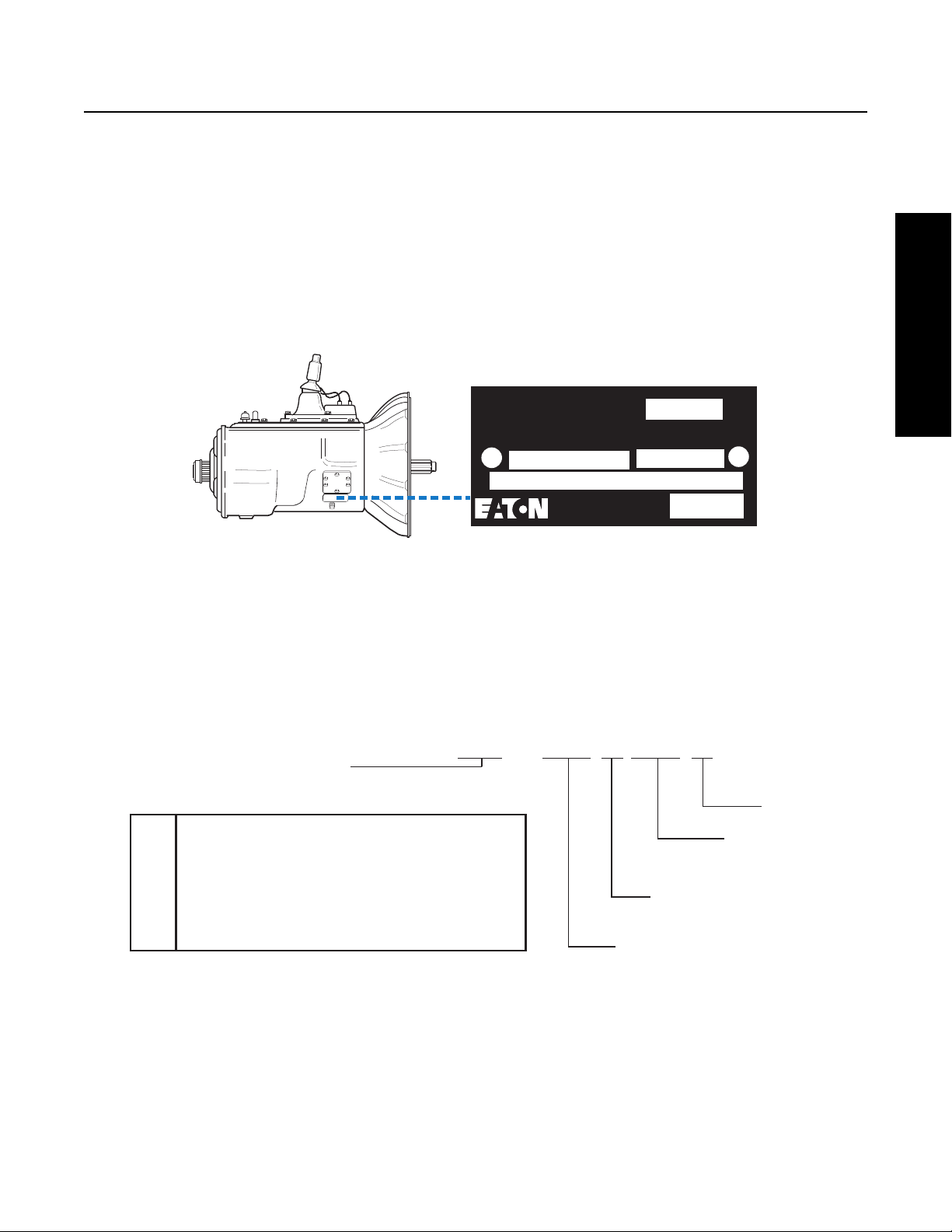
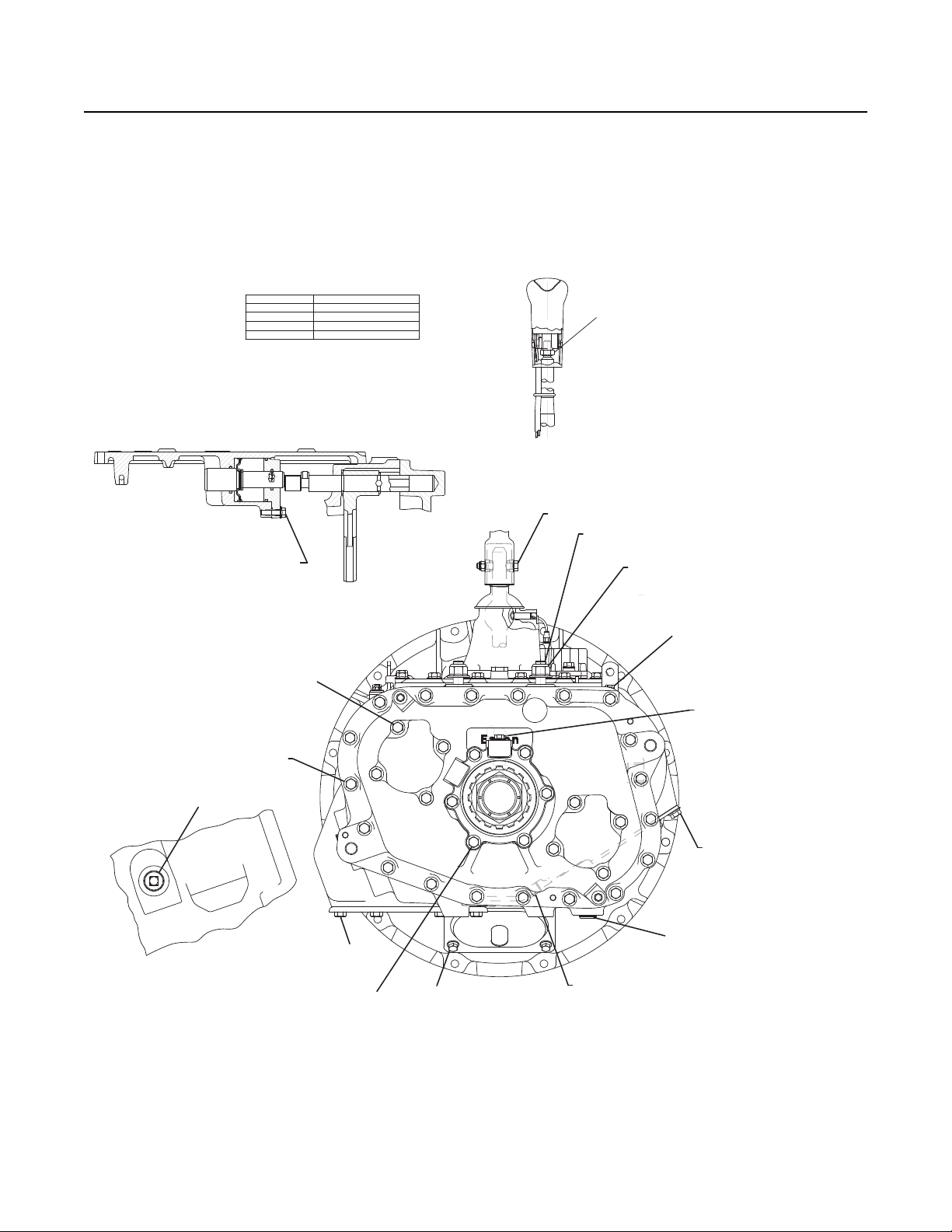
Serial Tag Information and Model Nomenclature
Transmission model designation and other Transmission Identification information are stamped on the Serial Tag. To identify the
Transmission Model and Serial Number, locate the Tag on the Transmission and then locate the numbers as shown. Figure 1-1
below shows the Tag which is located on the Transmission.
When calling for service assistance or parts, have the Model and Serial Numbers handy.
Do not remove or destroy the Transmission Identification Tag!
Transmission Tag and Location
Model Number
The Model Number gives basic information about the Transmission and is explained below. Use this number when calling for
service assistance or replacement parts.
Serial Number
The Serial Number is the sequential identification number of the Transmission. Before calling for service assistance, write the
number down as it may be needed.
Bill of Material or Customer Number
This number may be located below the Model and Serial Numbers. It is a reference number used by Eaton®.
Fig 1-1
Eaton Fuller
Transmissions
PTO Code
Model
Serial
Made
In
Eaton Corporation
Transmission Div
Kalamazoo, MI 49003
FRO-14210-C
FR
-
14210C
Ratio SetRatio Set
Forward SpeedsForward Speeds
This (x) 100 = Nominal Torque CapacityThis (x) 100 = Nominal Torque Capacity
= Helical Auxilary Gearing and = Helical Auxilary Gearing and
"Multi-Mesh" Front Gearing"Multi-Mesh" Front Gearing
EatonEaton Fuller Fuller Model Designation Prefix Model Designation Prefix
See options below:See options below:
Fuller Roadranger Twin CountershaftFuller Roadranger Twin Countershaft
FRFFRF w/ Forward Shift Bar Housingw/ Forward Shift Bar Housing
FROFRO w/ Overdrive w/ Overdrive
FROFFROF
w/ Overdrive and Forward Shift Bar Housingw/ Overdrive and Forward Shift Bar Housing
PrefixPr ef ix
DefinitionDefin it ion
FRFR
2
Model Designations
6
Model Options
Torque Rating
The torque rating of the Transmission specified in the Model Number is the Input Torque Capacity in lb. ft. Various torque ratings
are available. For more information, call the Roadranger Help Desk at 1-800-826-HELP (4357).
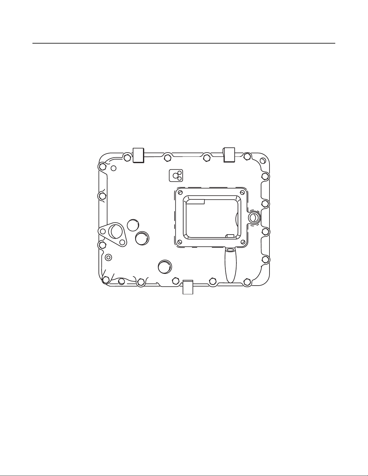
Two types of Shift Bar Housings are available for this Transmission. Both are described and shown below.
Shift Bar Housings
Standard: The standard Shift Bar Housing has a Gear Shift Lever opening that is located toward the rear of the Transmission. The
Housing is shown in figure 1-2.
Fig 1-2
Model Designations
7
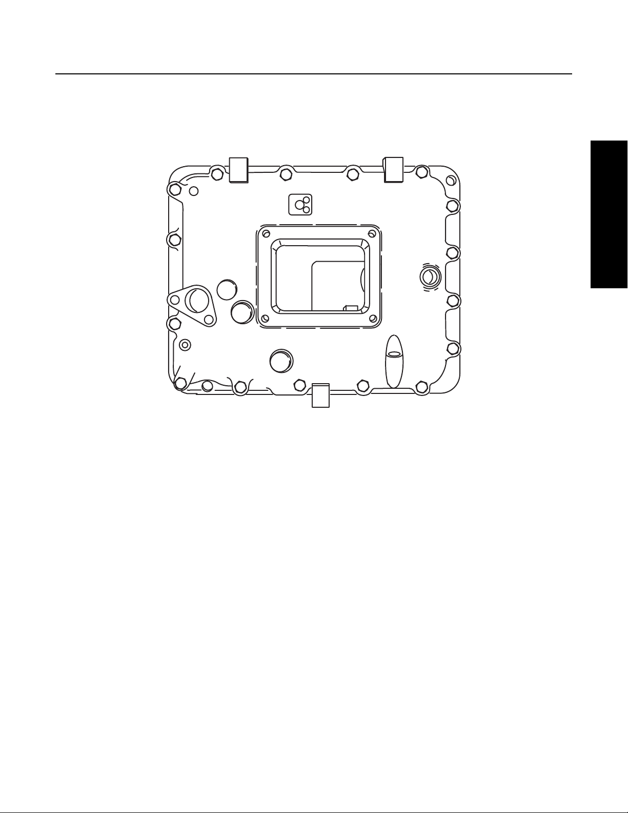
Model Designations
Forward Opening: The Forward Opening Shift Bar Housing has a Gear Shift Lever opening located three inches closer to the front
of the Transmission than the standard opening. This forward design allows greater flexibility in mounting the Transmission and
in indicated by an “F” in the Model Number. The Housing is shown in figure1-3.
Lubrication Pumps
Two types of lubrication pumps are available for use on this Transmission and are described below:
PTO Driven: A PTO Driven Pump is externally mounted on the 6 or 8 bolt PTO openings and driven off the PTO Gear.
Auxiliary Countershaft: An Auxiliary Countershaft Pump is mounted on the rear of the Transmission and driven off the
Auxiliary Countershaft.
Power Take Off (PTO) Usage
PTO’s can be mounted in the following ways:
6 or 8 Bolt: The 6 or 8 bolt openings are standard with the Transmission. The PTO is mounted to the opening and driven from the
PTO Gear on the Front Countershaft.
Thru-Shaft: The Thru-Shaft PTO mounts on the rear of the Transmission. It requires a special Auxiliary Housing and Main Case
Countershaft with internal splines.
Fig 1-3

Lubrication
8
Transmission Lubrication
Reference Lubrication Manual TCMT-0021 on Roadranger.com or call 800-826-4357 for a list of approved transmission
lubricants.
Note: The use of lubricants not meeting these requirements will affect warranty coverage.
Transmission Filters should be changed during regular lube intervals. Inspection of the Transmission Filter should be
conducted during preventive maintenance checks for damage or corrosion. Replace as necessary.
IMPORTANT
Lubrication
9
Lubrication
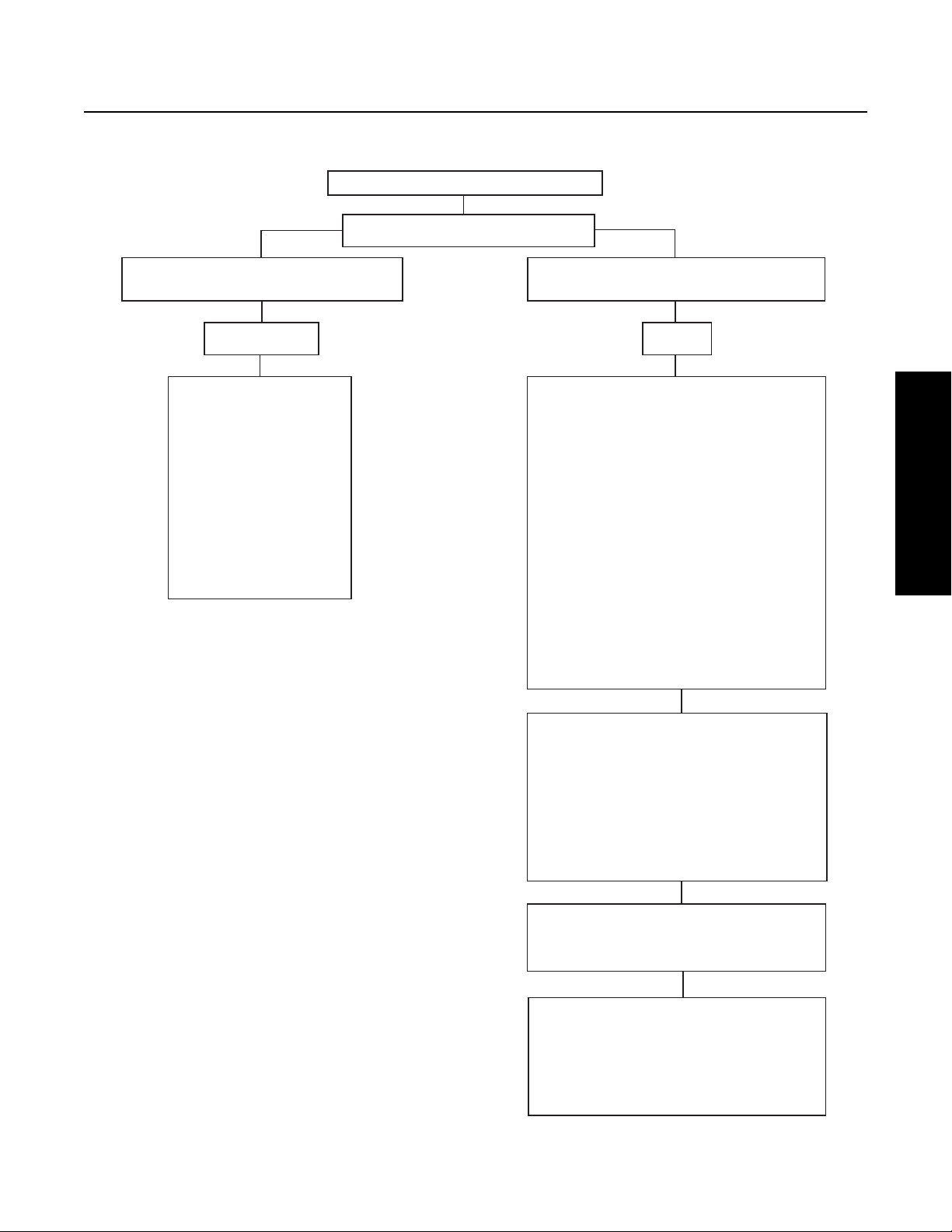
Oil Leak Inspection Process
Inspect for Oil Leak
Determine if it is a Weep or a Leak
Weep: Stained, damp, no drips, light oil film,
dirt adhered to the contaminated area.
Leak: Extremely wet or dripping of oil in the
contaminated area.
Gasket/Rear Seal Leak
1. Clean suspected oil weep
area with a clean dry cloth
or mild soluble degreaser.
2. Ensure lube is to proper
level.
3. Notify the customer that it
is only a weep and it is not
considered to be detrimental
to the life of the transmission.
4. Repair is complete.
1. Determine the origin of the leak path.
2. If origin of leak is obvious skip to Step 3.
3. If the origi
n of the oil leak is not obvious then
use either of the two following steps to determine
the oil leak:
Note: Do not use a high pressure spray washer to
clean the area. Use of a high pressure spray may
force contamination into the area of concern and
temporarily disrupt the leak path.
i. Clean area with a clean dry cloth or mild
soluble degr
easer and fill the transmission to
the proper lube level.
OR
ii. Clean the area as noted above and insert tracer
dye into the transmission lube and fill
transmission to proper lube level.
Operate vehicle to normal transmission operating
temperature and inspect the a
rea for oil leak(s)
visually or if tracer dye was introduced use an UVL
(Ultraviolet Light) to detect the tracer dye’s point
of origin.
Note: When inspecting for the origin of the leak(s)
make sure the assumed leak area is not being
contaminated by a source either forward or above
the identified area such as the engin
e, shift tower,
shift bar housing, top mounted oil cooler, etc...
Once the origin of the leak is identified, repair the
oil leak using proper repair procedures from the
designated model service manual.
After the repair is completed, verify the leak is
repaired and operate the vehicle to normal
transmission operatin
g temperature.
Inspect repaired area to ensure oil leak has been
eliminated. If the leak(s) still occurs, repeat steps
or contact the Roadranger Call Center at
1-800-826-4357.
Step 1
Step 2
Step 3
Step 4
Tools
10
Tool Specifications
Some repair procedures pictured in this manual show the use of specialized tools. Their actual use is recommended as they make
Transmission repair easier, faster, and prevent costly damage to critical parts.
For the most part, ordinary mechanic's tools such as socket wrenches, screwdrivers, etc., and other standard shop items such as
a Press, Mauls and Soft Bars are the only tools needed to successfully disassemble and reassemble any Eaton®Fuller®
Transmission.
The following tables list and describe the typical tools required to properly service this model Transmission above and beyond the
necessary basic wrenches, sockets, screwdrivers, and prybars.
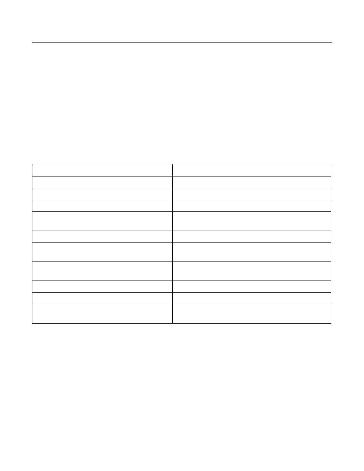
General Tools
The following tools are available from several tool manufacturers such as Snap-On, Mac, Craftsman, OTC, and many others.
Tool Purpose
0–100 lb. ft. 1/2" drive Torque Wrench General torquing of fasteners (Typically 15–80 lb. ft.)
0–800 lb. ft. Torque Wrench Torque Output Nut to 650–700 lb. ft.
0–50 lb. in. 3/8" drive Torque Wrench General torquing of fasteners
0–30 lb. in. 1/4" drive Torque Wrench Torquing of capscrews to 7 lb. in. during auxiliary countershaft
bearing endplay setting procedure
70 MM or 2 3/4" Socket - Standard Depth To remove the output yoke nut
Snap Ring Pliers - Large Standard External To remove the snap rings at the auxiliary drive gear, input shaft
bearing, and countershaft bearings
Feeler Gauges To set mainshaft washer endplay and auxiliary tapered bearing
endplay
Crow's Foot Pry Bar To remove the auxiliary drive gear bearing
(2) Air Pressure Gauges 0–100 PSI To troubleshoot and verify correct operation of air system
Bushing Driver To remove and install clutch housing bushings.
Bushing OD = 1.125", ID = 1.000"
Tools
11
Tools
Special Tools
The following Transmission Tools are available directly from K-Line Industries. To obtain any of these tools listed, contact K-Line
by phone or visiting the online store.:
K-Line Industries, Inc.
315 Garden Avenue
Holland, MI 49424
1-800-824-KLINE (5546)
http://www.klineind.com/
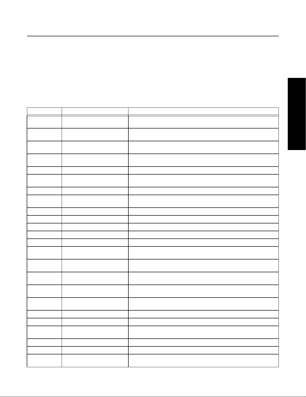
K-Line Part # Tool Tool Description
RR1001TR-1 Driver - Output Seal Slinger Used to install Output Seal Protective Slinger on FR & RT-series (Gen 9)
Transmission Output Yokes.
RR1001TR-2 Driver - Output Seal Used to install Output Seal in Rear Bearing Cover on RT-series (Gen 6 & 7)
Transmissions with 2.75" Output Shaft.
RR1001TR-8 Driver - Output Seal Used with Seal Driver RR1001TR-2 to install Output Seal in Rear Bearing
Cover on FR & RT-series (Gen 9) Transmissions.
RR1002TR Auxiliary Countershaft Support
Straps
Used to support the Auxiliary Countershaft Assemblies when servicing the
Auxiliary Section on FR & RT-series (Gen 7 & 9) Transmissions.
RR1004TR Mainshaft Lifting Hook Used to remove/install Mainshaft Assembly into the Transmission Main Case.
RR1005TR Driver - Input Shaft Bearing Used to install the Input Bearing on Transmissions with 2" & 1.75" Input
Shafts.
RR1006TR Auxiliary Section Lifting Bracket Used to lift Transmission Auxiliary Sections.
RR1007TR Shimming Gauge - Auxiliary
Countershaft (0.100")
Used for setting proper Auxiliary Countershaft Bearing clearance on
FR-series and RT-series (Gen 7 & 9) Transmissions.
RR1010TR Slide Hammer Used to remove Bearing Races, Reverse Idler Shafts, and Seals.
RR1011TR-1 Slide Hammer Attachment Used for removing Output Seals.
RR1011TR-2 Slide Hammer Attachment Used for removing Bearing Races from the Transmission Case.
RR1011TR-3 Slide Hammer Attachment Used for removing Bearing Races from the Transmission Case.
RR1011TR-4 Slide Hammer Attachment Used for removing Reverse Idler Shafts on FR-series Transmissions.
RR1012TR-5 Driver - Auxiliary Countershaft
Bearings
Used to install Auxiliary Countershaft Bearings on FR &
RT-series Transmissions with Auxiliary Section Helical Gearing.
RR1013TR Timing Block - RT-series
Countershaft
Used to support the Upper Countershaft during Main Box assembly on
RT-series Transmissions.
RR1014TR Puller - Countershaft Front
Bearings
Used to remove Front Countershaft Bearing on FR-series Transmissions.
RR1015TR Driver - Countershaft Front/Rear
Bearings
Used to install Front and Rear Countershaft Bearing on
FR-series Transmissions.
RR1017TR Pusher - Countershaft Used to push the Countershaft Assembly rearward to create clearance for
Bearing Puller on FR & RT-series Transmissions.
RR1019TR Hand Maul Used with Bearing and Seal Drivers for part installation/removal.
RR1020TR Soft Bar Used with Hand Maul to remove parts from the Transmission.
RR1022TR Countershaft Support Tool Used to support the Upper Countershaft during Main Box disassembly on
FR & RT-series Transmissions.
RR1023TR Puller - Input Bearing Used to remove the Input Bearing on FR & RT-series Transmissions.
RR1024TR Driver - Output Bearing Used to install the Output Bearing on FR & RT-series Transmissions.
RR1025TR Timing Block - FR-series
Countershaft
Used to support the Upper Countershaft during Main Box assembly on
FR-series Transmissions.

Tools
12
Shop Equipment
Eaton Aftermarket Parts
The following tools are available through Eaton Aftermarket Parts. To obtain any of the tools listed, contact your local Eaton
parts distributor:
20 Ton Capacity Press To press Countershaft Gears from Countershaft.
Tool Purpose Eaton Part Number
5/32" Air Line Release Tool To remove 5/32" air lines from
push-to-connect fittings.
P/N 4301157 included in Kit K-2394.
Air Line Cutting Tool To cut plastic air lines smoothly
and squarely.
P/N 4301158 included in Kit K-2394.
Torque Specifications
13
General Information
Torque Specifications
OUTPUT NUT
881-949 N.m [650-700 lb.ft.]
Install Output Nut onto a clean,
oil free shaft.
Note: DO NOT reuse Output Nut,
replace with new if removed
from shaft.
AUX DRIVE GEAR
BEARING RETAINER CAPSCREWS
54-61 N.m [40-45 lb.ft.]
M10x1.5 THREAD
SHIFT LEVER HOUSING CAPSCREWS
54-61 N.m [40-45 lb.ft.]
M10x1.5 THREAD
SHIFT BLOCK TO SHIFT ROD CAPSCREW
54-61 N.m [40-45 lb
.ft.]
M10x1.5 THREAD
COUNTERSHAFT FRONT BEARING
RETAINER CAPSCREWS
122-162 N.m [90-120 lb
.ft.]
.625-18-THREAD
CLUTCH HOUSING CAPSCREWS
ALUMINUM HOUSING
CAST IRON HOUSING
97-108 N.m [72-80 lb
.ft.]
M12x1.75 THREAD
FRONT BEARING COVER CAPSCREWS
54-61 N.m [40-45 lb
.ft.]
M10x1.5 THREAD
CLUTCH HOUSING STUDS
81 N.m [60 lb.ft.] MIN
M16x2 THREAD
DRIVEN UNTIL BOTTOMED
CLUTCH HOUSING NUTS
ALUMINUM HOUSING
CAST IRON HOUSING
244-271 N.m [180-200 lb
.ft.]
M16x1.5 THREAD
Torque Specifications
14
.375 - 18
.250 - 18
PIPE THREAD SIZE
.0625 - 27 6.8-9.5 N.m [60-84 lb.in]
HYDRAULIC LINE SEALANT
20.3-27.1 N.m [180-240 lb.in]
33.9-47.5 N.m [300-420 lb.in]
.125 - 27 9.5-13.6 N.m [84-120 lb.in]
PIPE THREAD TORQUE SPECIFICATIONS. UNLESS OTHERWISE SPECIFIED:
MASTER VALVE JAM NUT
48-61 N.m [35-45 lb
.ft.]
.500-13 THREAD
SUPPORT STUDS
81 N.m [60 lb.
ft.]
M16x2 THREAD
DRIVE UNTIL BOTTOMED
SUPPORT STUD NUTS
230-257 N.m [170-190 lb
.ft.]
M16x1.5 THREAD
CAPTIVATED LIFTING EYE CAPSCREWS
54-61 N.m [40-45 lb
.ft.]
M10x1.5 THREAD
SPEEDO SENSOR CAPSCREW
27-31 N.m [20-23 lb
.ft]
M8x1.25 THREAD
SMALL PTO COVER CAPSCREWS
54-61 N.m [40-45 lb.ft.]
M10x1.5 THREAD
OIL DRAIN PLUG
61-74 N.m [45-55 lb
.ft.]
.750 PIPE THREAD
THERMOCOUPLE PLUG
54-67 N.m [40-50 lb
.ft.]
.500 PIPE THREAD
REAR BEARING COVER CAPSCREWS
54-61 N.m [40-45 lb
.ft.]
M10x1.5 THREAD
HAND HOLE COVER CAPSCREWS
19-24 N.m [14-18 lb
.ft.]
.3125-18 THREAD
LARGE PTO COVER CAPSCREWS
77-88 N.m [57-65 lb
.ft.]
M12x1.75 THREAD
AUX C'SHAFT REAR BEARING COVER CAPSCREWS
54-61 N.m [40-45 lb.ft.]
M10x1.5
AUX HOUSING CAPSCREWS
54-61 N.m [40-45 lb
.ft.]
M10x1.5 THREAD
OIL FILL PLUG
47-67 N.m [35-50 lb
.ft.]
1.0625-12 THREAD
RANGE COVER TO SBH
RANGE CYL CAPSCREWS
27-31 N.m [20-23 lb
.ft.]
M8x1.25 THREAD
SHIFT LEVER SHOULDER BOLT AND NUT
14-16 N.m [10-12 lb.ft.]
.3125-18 THREAD
Power Flow
15
General Information
Power Flow Diagrams
An understanding of the engine’s power flow through a Transmission in each particular gear will assist the technician in
troubleshooting and servicing a Transmission.
The Eaton Fuller Roadranger Transmission can be thought of as two separate “Transmissions” combined into one unit. The first
“Transmission” or Front Section contains six gear sets which are shifted with the Gear Shift Lever. The second “Transmission”
called the Auxiliary Section, contains two gear sets and is shifted with air pressure.
Note: This Transmission is referred to as a constant mesh type Transmission. When in operation, all gears are turning even
though only some of them are transferring power.
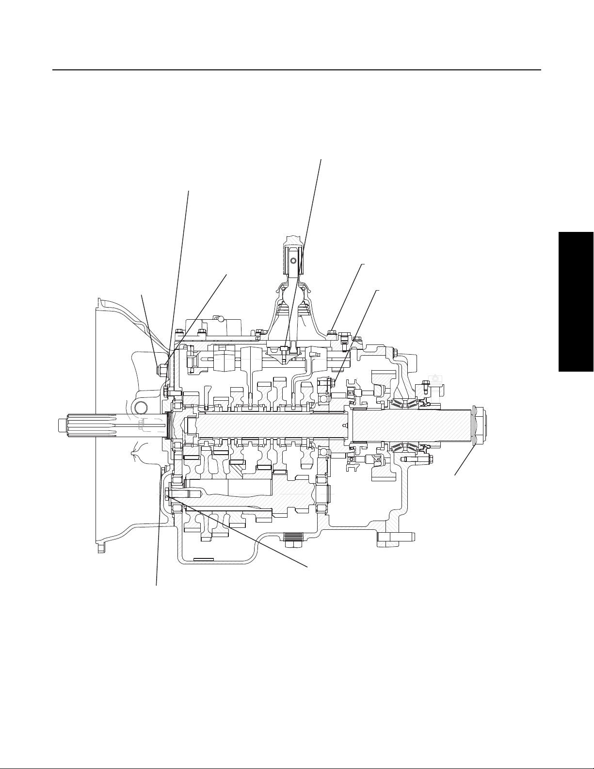
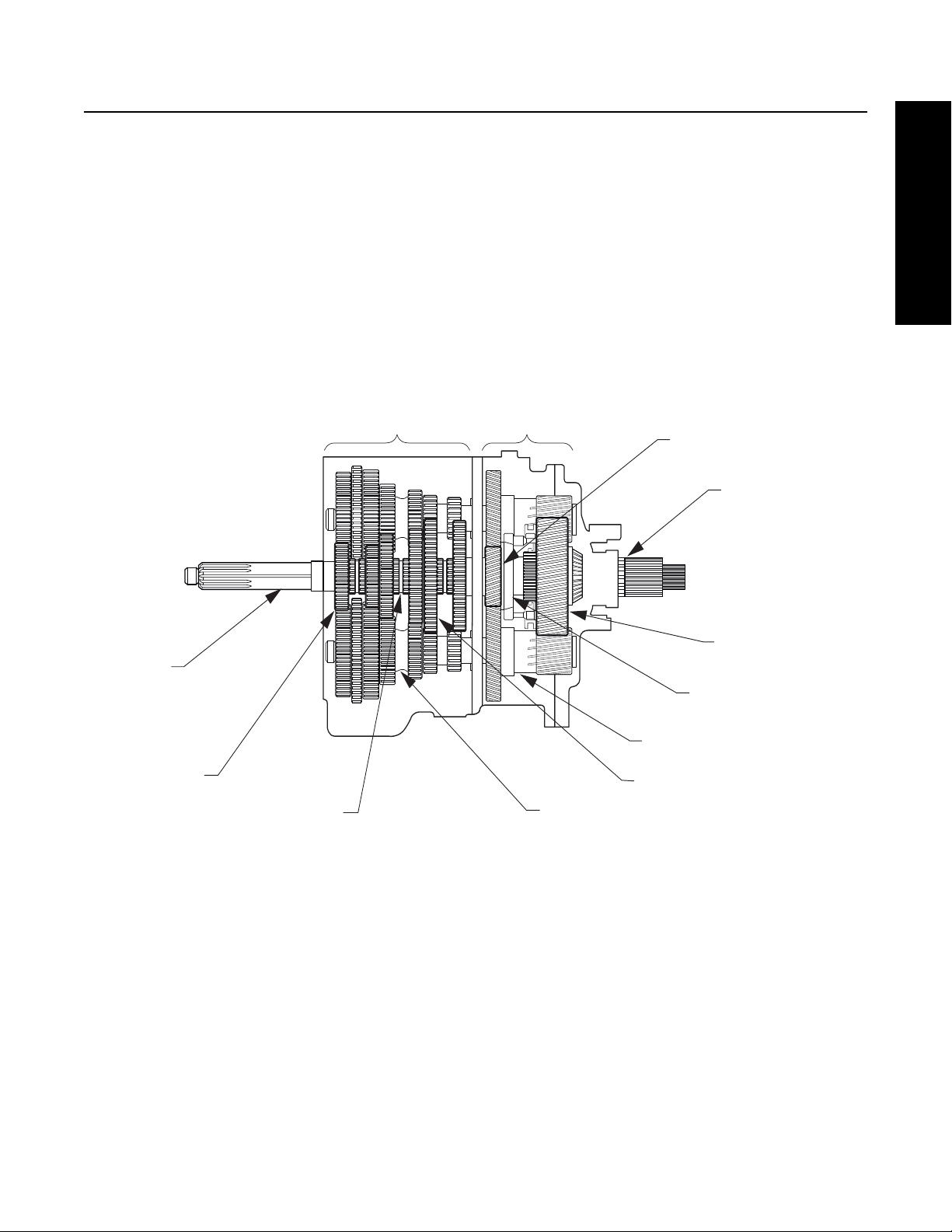
Figure 2-3 below shows the Transmission with the main components called out. Note that the Transmission is in the Neutral
position because the Sliding Clutches are all in their center positions and not engaged is any gears.
Figure 2-3. Transmission Components Important for Understanding Power Flow
Front Section
Input Shaft
Main Drive Gear
Sliding Clutch
Countershaft
Mainshaft Gear
Auxiliary Countershaft
Range Sliding Clutch
Auxiliary Mainshaft
Reduction Gear
Output Shaft
(Auxiliary Mainshaft)
Auxiliary Drive Gear
Auxiliary Section

Power Flow
16
Front Section Power Flow
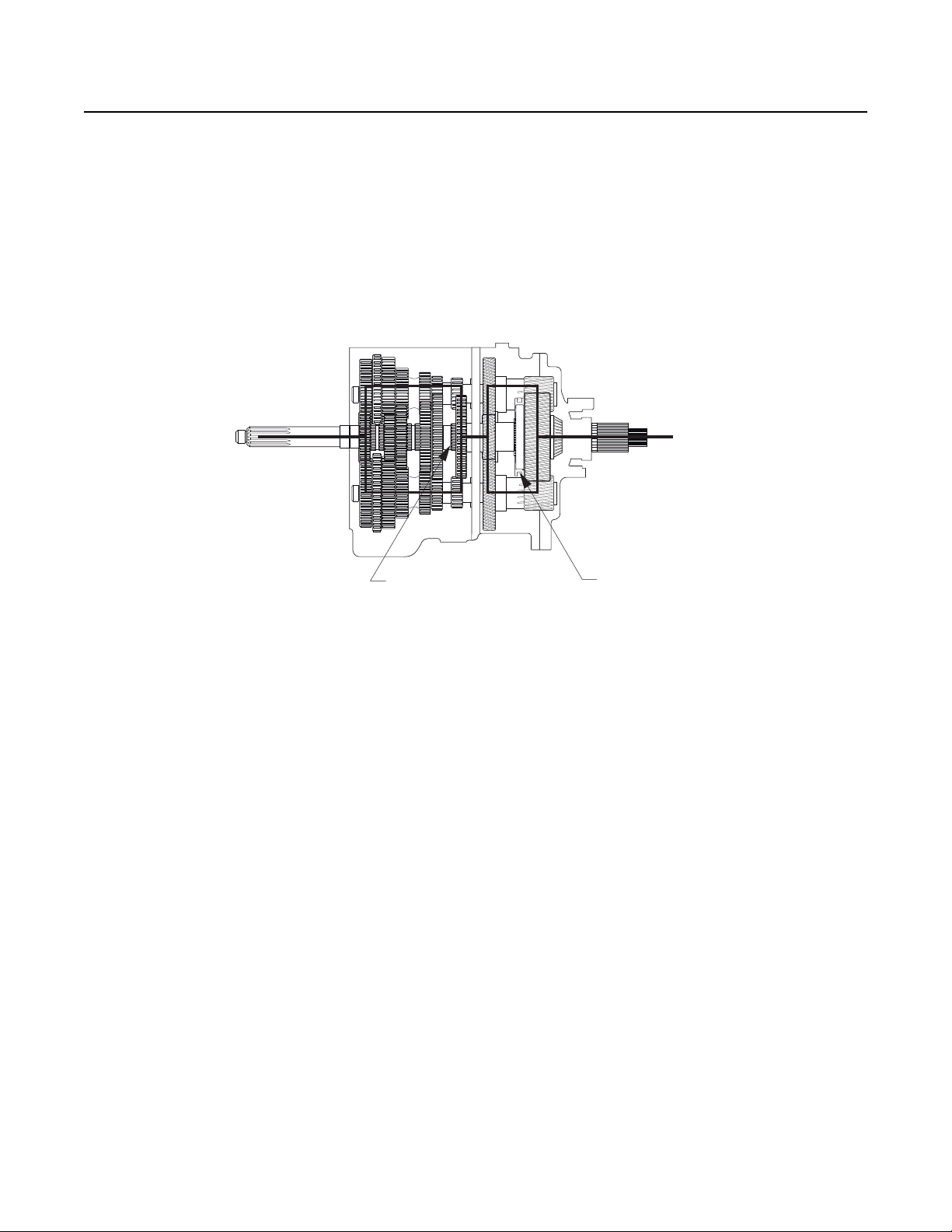
Note: The heavy lines in Figure 2-4 outline the power flow description below. For help in understanding the Transmission
components, refer to Figure 2-3.
1. Power (torque) from the vehicle’s engine is transferred to the Transmission’s Input Shaft.
2. The Input Shaft rotates the Main Drive Gear through internal splines in the hub of the gear.
3. The Main Drive Gear meshes with both Countershaft driven gears and the torque is split between both Countershafts.
4. Because the Countershaft Gears are in constant mesh with the Mainshaft Gears, all the Front Section gearing rotates.
However, only the engaged Mainshaft Gear will have torque. External clutching teeth on the Sliding Clutch will engage
internal clutching teeth on the selected Mainshaft Gear. Torque will now be provided from both opposing Countershaft
Gears, into the engaged Mainshaft Gear, and through the Sliding Clutch to the Front Section Mainshaft.
5. The rear of the Front Section Mainshaft is spined into the Auxiliary Drive Gear and torque is now delivered to the
Auxiliary Section.
Figure 2-4 Front Section Torque (1st Gear)
Sliding Clutch Forward
Sliding Clutch Bac
k

Power Flow
17
General Information
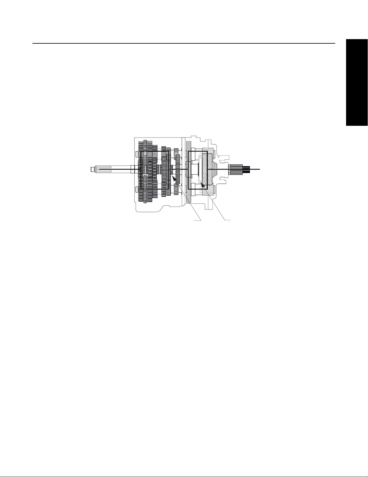
Front Section Power Flow - Direct Gear
In direct gear (5th/10th for FR model, 4th/9th for FRO model), the Front Sliding Clutch is moved forward and engages into the
back of the Main Drive Gear. Torque will flow from the Input Shaft to the Main Drive Gear, Main Drive Gear to Sliding Clutch, Sliding
Clutch straight into the Front Section Mainshaft which delivers the torque to the Auxiliary Drive Gear.
Note: All Countershaft and Mainshaft Gears will rotate, but the gears will not be loaded.
Figure 2-5 5th Gear FR, 4th Gear FRO
Figure 2-6 10th Gear FR, 9th Gear FRO
Sliding Clutch Forward
Sliding Clutch Bac
k
Sliding Clutch Forward
Sliding Clutch Forward
Power Flow
18
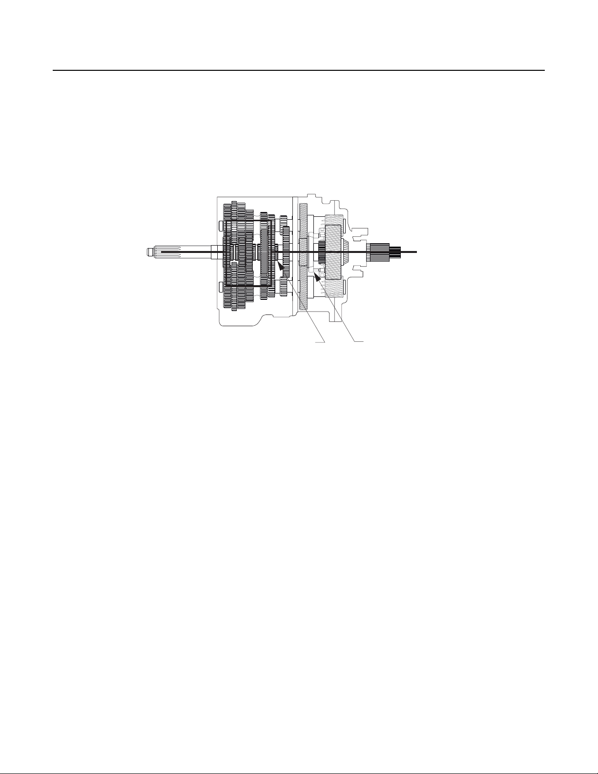
Front Section Power Flow - Reverse Gear
Torque will flow from the Countershafts to the Reverse Idler Gears. Torque will then flow from the Reverse Idler Gears to the
Mainshaft Reverse Gear. Torque will now travel through the Mainshaft Reverse Gear, the Sliding Clutch in the Reverse position
and then to the Mainshaft and Auxiliary Drive Gear.
Note: The Idler Gears cause the reversal of rotation.
Figure 2-7 Reverse Gear - Low Range
Sliding Clutch Back Sliding Clutch Back
Power Flow
19
General Information
Auxiliary Section Power Flow - Low Range
The Auxiliary Drive Gear transfers torque to both Auxiliary Countershafts.
If the Auxiliary Section is in Low Range, the Range Sliding Clutch is rearward and engaged into the Auxiliary Mainshaft Reduction
Gear. Torque will flow from the Auxiliary Countershafts, into the Auxiliary Mainshaft Reduction Gear, through the Range Sliding
Clutch and then into the Output Shaft (Auxiliary Mainshaft).
Figure 2-8 Low Range (Sliding Clutch Back)
Sliding Clutch Forward
Sliding Clutch Back
Power Flow
20
Auxiliary Section Power Flow - High Range
If the Auxillairy Section is in High Range, the Range Sliding Clutch is forward and engaged into the back of the Auxiliary Drive Gear.
Torque will flow from the Auxillairy Drive Gear to the Range Sliding Clutch. Because the Range Sliding Clutch has internal splines
which connect to the Output Shaft, torque will flow straight through the Auxiliary Section.
Note: The auxiliary gearing will still turn, but the gears will not be loaded.
Figure 2-9 High Range Selected (Sliding Clutch Forward)
Sliding Clutch Forward
Sliding Clutch Forward
Power Flow
21
General Information
FR/FRO-1X210
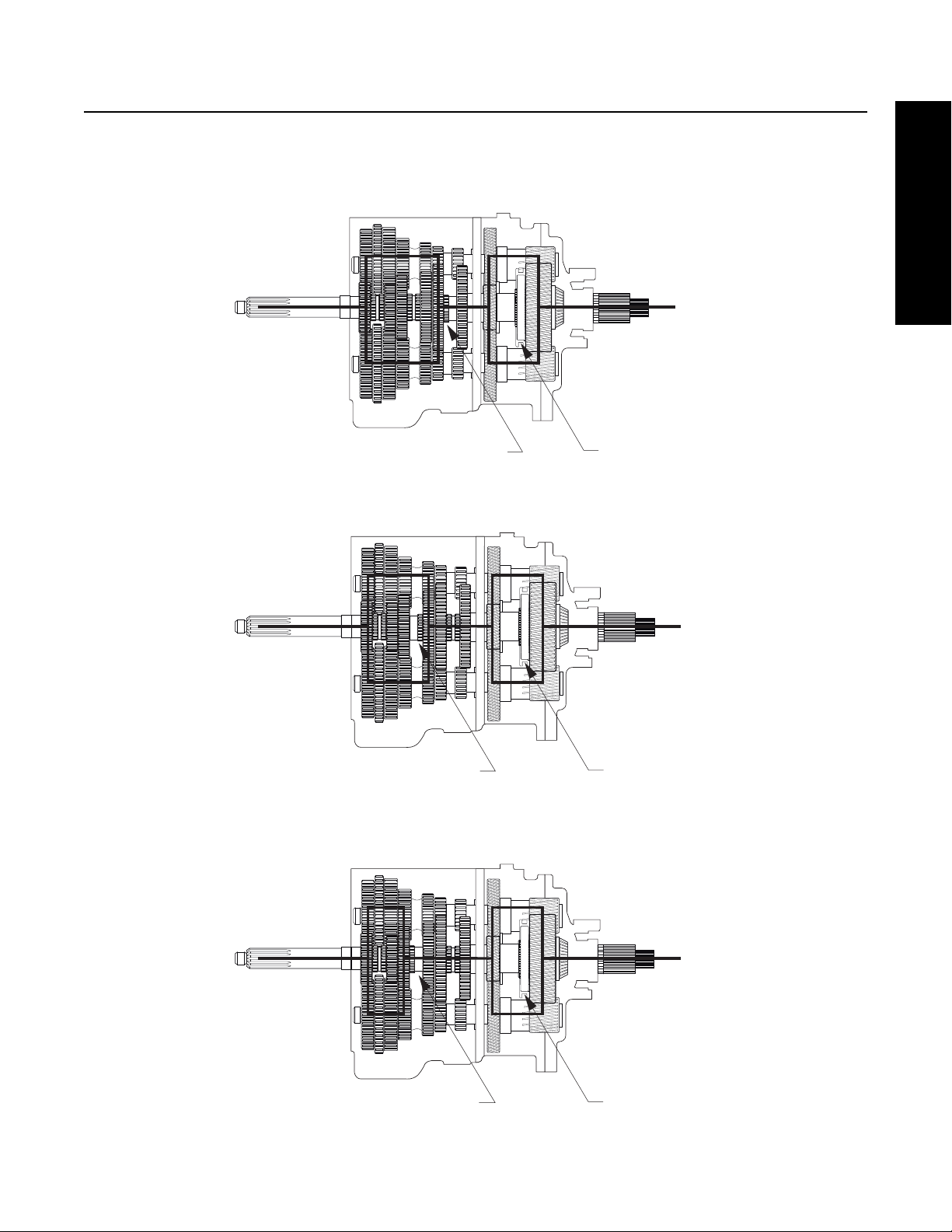
1st Gear
2nd Gear
3rd Gear
Sliding Clutch Forward
Sliding Clutch Back
Sliding Clutch Back
Sliding Clutch Bac
k
Sliding Clutch Forward
Sliding Clutch Back
Power Flow
22
4th Gear-FR/Direct Drive Transmission
5th Gear- FRO/Overdrive Transmission
5th Gear- FR/Direct Drive Transmission
4th Gear FRO/Overdrive Transmission
6th Gear
Sliding Clutch Back
Sliding Clutch Back
Sliding Clutch Forward
Sliding Clutch Bac
k
Sliding Clutch Forward
Sliding Clutch Forward

Power Flow
23
General Information
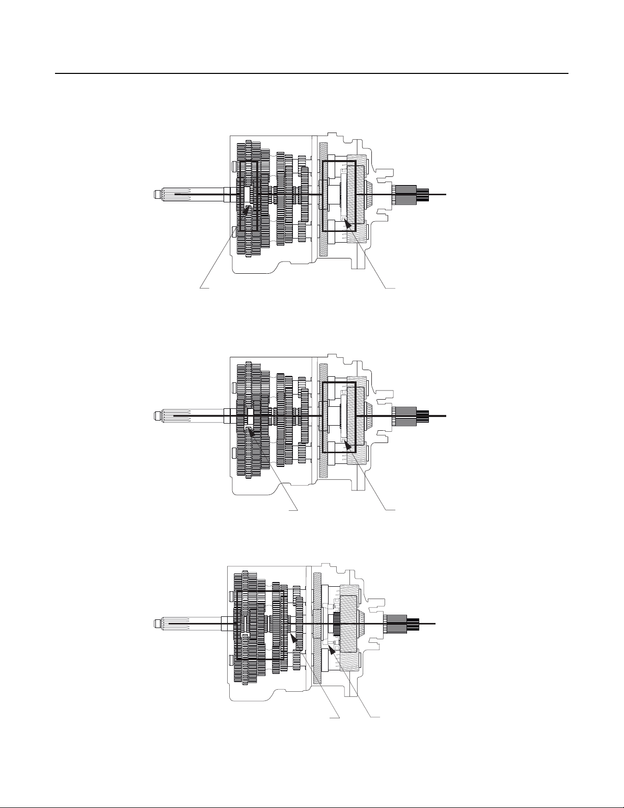
7th Gear
8th Gear
9th Gear-FR/Direct Drive Transmission
10th Gear-FRO/Overdrive Transmission
Sliding Clutch Back
Sliding Clutch Forward
Sliding Clutch Forward
Sliding Clutch Forward
Sliding Clutch Back
Sliding Clutch Forward

Power Flow
24
10thGear-FR/Direct Drive Transmission
9th Gear-FRO/Overdrive Transmission
Sliding Clutch Forward
Sliding Clutch Forward

Air System Troubleshooting
25
General Information
Air System Troubleshooting
The symptoms listed below are covered on the following pages. Before beginning any of those troubleshooting procedures, place
the Transmission in Neutral and move the Range Selection Lever from Low to High. Listen for any constant air leak from the Shift
Knob, Air Module Base (exhaust), or Transmission Breather. If a constant leak is heard, go to that particular leak troubleshooting
procedure first.
If you do not see the symptom you need to correct, refer to the General Troubleshooting Chart.
Symptom
• Air Leak from Air Module Base (Exhaust Leak)
• No or Slow Range Shift into High (Shift into Low Range is good)
• No or Slow Range Shift into Low (Shift into High Range is good)
• Constant Air Leak from Shift Knob
• Range Shifts in Gear
• Air Leak from Transmission Breather or Transmission Case is Pressurized
Note: Use the Air System Troubleshooting Procedures for part replacement only if the symptom can be duplicated. If the problem
is intermittent, parts that are not defective could be replaced.
Note: During all testing, the vehicle air pressure must be greater than 90 PSI (620 kPa). If during testing the pressure falls below
90 PSI (620 kPa), make sure the Transmission is in Neutral, start the engine and let the pressure build to governor cutoff.
After the pressure reaches the governor cutoff, continue testing. The pressure is critical if the vehicle is equipped with a
Vehicle Air System Pressure Protection Valve that would shut off the air supply to certain air circuits if the system pressure
dropped below a preset level.
Note: A 0–150 PSI (0–1034 kPa) Air Gauge with a 1/16" male pipe thread fitting attachment is required for some of the test
procedures.
Note: Regulated air pressure is 75–85 PSI (517–586 kPa).
Prior to removing the Air Module, exhaust the air from it. Failure to exhaust the Air Module may result in personal injury or
damage to parts from the sudden release of air.
Use care when removing the Test Port Pipe Plugs. If air pressure is present on the plug, it can become a projectile during
removal. When removing the “L” plug or “H” plug, pressure can be shut off by selecting the opposite range mode. If
removing the “F” plug, exhaust the air to the Module Inlet.
WARNING
Loading...