


Troubleshooting Manual
Gen II Automated Transmissions
TRTS0062 EN-US
May 2013
FO-6406A-ASW FO-6406A-ASX FO-8406A-ASW FO-8406A-ASX RT-14910B-AS2 RTLO-14918A-AS2 RTLO-16918A-AS2 RTLO-18918A-AS2 RTLO-20918A-AS2 RTLO-22918A-AS2 RTO-10710B-AS2 RTO-10910B-AS2 RTO-10910B-DM2
RTO-12710B-AS2 RTO-12910B-AS2 RTO-12910B-DM2 RTO-14710B-AS2 RTO-14710C-AS2 RTO-14910B-AS2 RTO-14910B-DM2 RTO-14910C-AS2 RTO-16710C-AS2 RTO-16910B-AS2 RTO-16910B-DM2 RTO-16910C-AS2 RTO-18910B-AS2

TRTS0062 |
Table of Contents |
Table of Contents
General Information
Warnings and Cautions . . . . . . . . . . . . . . . . . . . . . . . . .1
Suggested Tools . . . . . . . . . . . . . . . . . . . . . . . . . . . . . .2
Air Gauges . . . . . . . . . . . . . . . . . . . . . . . . . . . . . . . .2
Volt/Ohm Meter . . . . . . . . . . . . . . . . . . . . . . . . . . . .2
PC-based Service Tool “ServiceRanger” . . . . . . . . .2
Shift Lever Tester . . . . . . . . . . . . . . . . . . . . . . . . . .2
Eaton Test Adapter Kit . . . . . . . . . . . . . . . . . . . . . . .2
6-Pin Deutsch Diagnostic Adapter . . . . . . . . . . . . . .2
Transmission Models Included . . . . . . . . . . . . . . . . . . .3
Diagnostic Procedure . . . . . . . . . . . . . . . . . . . . . . . . . .4
Fault Code Retrieval/Clearing . . . . . . . . . . . . . . . . . . . .5
Retrieving Fault Codes . . . . . . . . . . . . . . . . . . . . . .5
Clearing Fault Codes . . . . . . . . . . . . . . . . . . . . . . . .6
Driving Techniques . . . . . . . . . . . . . . . . . . . . . . . . . . . .7
Fault Code Isolation Procedure Index . . . . . . . . . . . . .12
Symptom-Driven Diagnostics Index . . . . . . . . . . . . . .14
Electrical Pretest Procedure
Electrical System Pretest . . . . . . . . . . . . . . . . . . . . . .15
Power-Up Sequence Pretest . . . . . . . . . . . . . . . . . . . .18
Air Pretest . . . . . . . . . . . . . . . . . . . . . . . . . . . . . . . . . .24
Fault Isolation Procedure |
|
Fault Code 11: Shift Controller . . . . . . . . . . . . . . . . . |
.28 |
Fault Code 12: Transmission Controller . . . . . . . . . . |
.32 |
Fault Code 14: Invalid Lever Position . . . . . . . . . . . . |
.36 |
Fault Code 16: Eaton Proprietary Link (EPL) . . . . . . . |
.42 |
Fault Code 17: Start Enable Relay Coil . . . . . . . . . . . |
.48 |
Fault Code 26: Clutch Slip . . . . . . . . . . . . . . . . . . . . . |
.54 |
Fault Code 27: Clutch Disengagement . . . . . . . . . . . . |
.58 |
Fault Code 28: Clutch System Fault . . . . . . . . . . . . . . |
.62 |
Fault Code 31: Momentary Engine Ignition |
|
Interrupt Relay (MEIIR) . . . . . . . . . . . . . . . . . . . . . . . |
.68 |
Fault Code 32: Switched System Voltage . . . . . . . . . |
.74 |
Fault Code 33: Battery Voltage Supply . . . . . . . . . . . |
.78 |
Fault Code 35: J1939 Data Link . . . . . . . . . . . . . . . . |
.82 |
Fault Code 41: Range Failed to Engage . . . . . . . . . . . |
.88 |
Fault Code 42: Splitter Failed to Engage . . . . . . . . . . |
.92 |
Fault Code 43: Range Valve . . . . . . . . . . . . . . . . . . . . |
.96 |
Fault Code 44: Inertia Brake Solenoid Coil . . . . . . . . |
102 |
Fault Code 46: Splitter Valve . . . . . . . . . . . . . . . . . . . |
108 |
Fault Code 51: Rail Select Sensor . . . . . . . . . . . . . . . |
114 |
Fault Code 52: Gear Select Sensor . . . . . . . . . . . . . .120 Fault Code 56: Input Shaft Speed Sensor . . . . . . . . .124 Fault Code 57: Main Shaft Speed Sensor . . . . . . . . .130 Fault Code 58: Output Shaft Speed Sensor . . . . . . . .134 Fault Code 61: Rail Select Motor . . . . . . . . . . . . . . . .140 Fault Code 63: Gear Select Motor . . . . . . . . . . . . . . .146 Fault Code 65: Logic Power . . . . . . . . . . . . . . . . . . .152 Fault Code 71: Stuck Engaged . . . . . . . . . . . . . . . . . .158 Fault Code 72: Failed to Select Rail . . . . . . . . . . . . . .162 Fault Code 73: Failed to Engage Gear . . . . . . . . . . . .166 Fault Code 74: Failed to Synchronize . . . . . . . . . . . .170 Fault Code 81: Gear Engagement Detected . . . . . . . .174 Fault Code 83: Missing Lever . . . . . . . . . . . . . . . . . .178 Fault Code 91: Power Connection . . . . . . . . . . . . . . .182 Fault Code 92: Weak System Battery Voltage . . . . . .186 Fault Code 93: Loss of J1939 Communication
from the Engine . . . . . . . . . . . . . . . . . . . . . . . . . . . .190
Symptom Isolation Procedure
Electrical System . . . . . . . . . . . . . . . . . . . . . . . . . . . .194
Front Box Control . . . . . . . . . . . . . . . . . . . . . . . . . . .204
Gear Display Power Supply . . . . . . . . . . . . . . . . . . . .208
Start Enable Relay Contact . . . . . . . . . . . . . . . . . . . .214
AutoShift Will Not Engage a Gear . . . . . . . . . . . . . . .220
UltraShift DM Will Not Engage a Gear . . . . . . . . . . . .228
UltraShift ASW Will Not Engage a Gear . . . . . . . . . . .236
J1587 Data Link . . . . . . . . . . . . . . . . . . . . . . . . . . . .242
Range System Test . . . . . . . . . . . . . . . . . . . . . . . . . .248
Splitter System . . . . . . . . . . . . . . . . . . . . . . . . . . . . .252
Up/Down Button Test . . . . . . . . . . . . . . . . . . . . . . . .256
UltraShift DM Shift Complaint . . . . . . . . . . . . . . . . . .260
UltraShift ASW Shift Complaint . . . . . . . . . . . . . . . . .266
UltraShift ASW Clutch Engagement . . . . . . . . . . . . .274
Transmission Air Leak . . . . . . . . . . . . . . . . . . . . . . .278
Shift Lever Back Light . . . . . . . . . . . . . . . . . . . . . . . .284
2013.07.17 |
© 2013 Eaton. All rights reserved |
i

Table of Contents |
TRTS0062 |
|
|
|
|
Appendix
Connector Pin Descriptions . . . . . . . . . . . . . . . . . . .288
Transmission Controller 18-Way
(Vehicle Interface Connector) . . . . . . . . . . . . . . .288
Transmission Controller 30-Way Connector . . . .289
Shift Controller 30-Way Connector . . . . . . . . . . .291
Wiring Diagrams . . . . . . . . . . . . . . . . . . . . . . . . . . . .294
6-Speed and 7-Speed AutoShift . . . . . . . . . . . . .294
6-Speed UltraShift ASW . . . . . . . . . . . . . . . . . . .296
10-Speed AutoShift . . . . . . . . . . . . . . . . . . . . . . .298
10-Speed UltraShift DM . . . . . . . . . . . . . . . . . . .300
18-Speed AutoShift . . . . . . . . . . . . . . . . . . . . . . .302
Eaton Shift Lever . . . . . . . . . . . . . . . . . . . . . . . . .304
OEM Shift Lever . . . . . . . . . . . . . . . . . . . . . . . . .304
Proper Clutch Operation . . . . . . . . . . . . . . . . . . . . . .306
Check For Proper Clutch Operation . . . . . . . . . . .306
Confirm Proper Clutch Adjustment
and Clutch Brake Contact . . . . . . . . . . . . . . . . . .306
Adapter Test Kit J43318 . . . . . . . . . . . . . . . . . . . . . .308
Gray Adapters . . . . . . . . . . . . . . . . . . . . . . . . . . .308
Purple Adapters . . . . . . . . . . . . . . . . . . . . . . . . . .308
Adapter Pins . . . . . . . . . . . . . . . . . . . . . . . . . . . .308
Troubleshooting Worksheet . . . . . . . . . . . . . . . . . . .309
ii
© 2013 Eaton. All rights reserved |
2013.07.17 |

TRTS0062 |
General Information | Warnings and Cautions |
Warnings and Cautions
!
!
!
Warning: Follow the specified procedures in the indicated order to avoid personal injury
Caution: Follow the specified procedures in the indicated order to avoid equipment malfunction or damage
Note: Additional relevant information not covered in the service procedure.
Before starting a vehicle:
•Sit in the driver's seat
•Place Shift Lever in neutral
•Set the parking brake
Before working on a vehicle or leaving the cab with engine running:
•Place Shift Lever in neutral
•Set the parking brake
•Block the wheels
When parking the vehicle or leaving the cab:
•Place Shift Lever in neutral
•Set the parking brake
Caution: Do not release the parking brake or attempt to select a gear until the air pressure is at the correct level.
To avoid damage to the transmission during towing:
1.Place Shift Lever in neutral
2.Lift the drive wheels off of the ground or disconnect the drivelink
Do not operate vehicle if Alternator light is lit or if gauges indicate low voltage.
2013.07.17 |
© 2013 Eaton. All rights reserved |
1 |

For parts or service call us Pro Gear & Transmission, Inc.
1(877) 776-4600
(407)872-1901 parts@eprogear.com
906 W. Gore St. Orlando, FL 32805

Suggested Tools | General Information |
TRTS0062 |
Suggested Tools
Air Gauges
•2 (0-100) PSI Air Gauges
Volt/Ohm Meter
•SPX / Kent-Moore 1 (800) 328-6657
•P/N 5505027
PC-based Service Tool “ServiceRanger”
•Contact your OEM
Shift Lever Tester
•Eaton Service Parts 1 (800) 826-4357
•P/N 691795
Eaton Test Adapter Kit
•SPX / Kent-Moore 1 (800) 328-6657
•P/N J-43318
6-Pin Deutsch Diagnostic Adapter
•SPX / Kent-Moore 1 (800) 328-6657
•P/N J-38500-60A
For more information call 1-800-826-HELP (826-4357)
2 |
© 2013 Eaton. All rights reserved |
2013.07.17 |

TRTS0062 |
General Information | Transmission Models Included |
Transmission Models Included
6-Speed |
7-Speed |
6-Speed ASW
18-Speed |
10-Speed
10-Speed DM
2013.07.17 |
© 2013 Eaton. All rights reserved |
3 |
Diagnostic Procedure | General Information |
TRTS0062 |
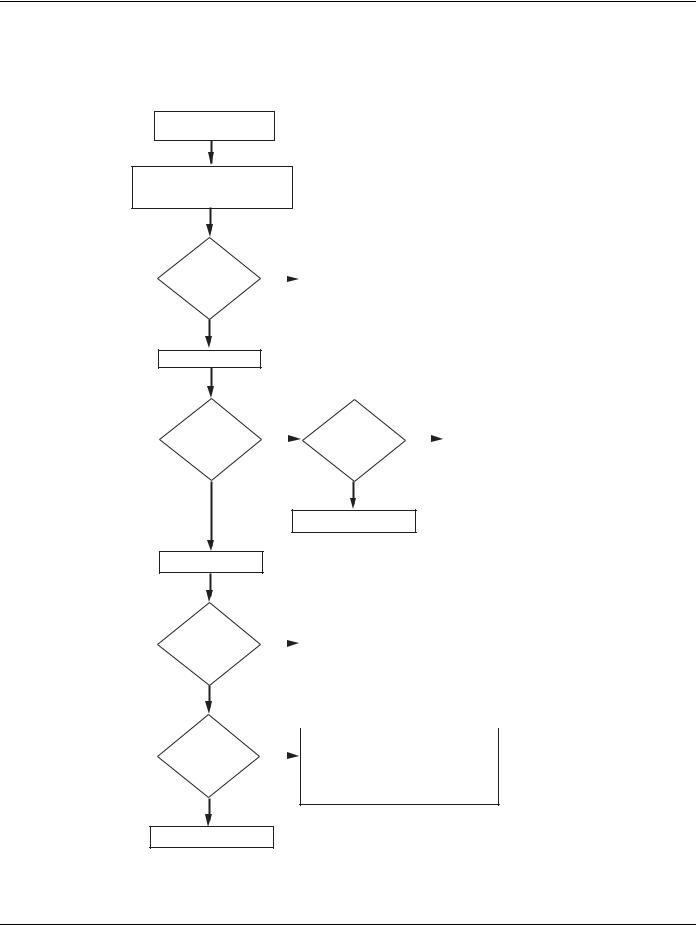
Diagnostic Procedure
Follow the flow chart below for all AutoShift failures. Perform tests and procedures as directed by the flowchart.
Key on.
Retrieve active codes. Note: Scan tool or P.C. may be required if service light is not avialable.
|
|
|
• Perform Electrical System Pretest |
Active codes? |
|
|
• Refer to the Fault Code Isolation |
YES |
|
Procedure Index to select a Fault |
|
|
|
||
|
|
Code Isolation Procedure |
|
|
|
|
|
|
|
|
|
NO
Observe Gear Display
Can a solid "N" be observed in Gear Display ?
YES
Retrieve Inactive Codes.
Inactive Codes?
NO
Symptom?
|
Will engine crank ? |
|
|
• |
Perform Power-Up Sequence Test |
NO |
NO |
|
• |
Perform Front Box Control Test |
|
|
|
||||
|
|
|
|
|
|
YES
• Perform Gear Display Test
|
|
• Record and clear codes |
|
|
|
|
• Perform Driving Technique to reproduce |
|
|
|
|
|
the inactive fault code |
|
|
|
• Perform Electrical System Pretest |
|
|
|
||||
YES |
|
• |
Perform Air Pretest |
|
|
|
• Refer to the Fault Code Isolation |
|
|
|
|
|
Procedure Index to select |
|
|
|
|
a fault code isolation procedure |
|
|
|
|
|
|
|
|
|
||
|
|
• Perform Electrical System Pretest |
||
|
|
• |
Perform Air Pretest |
|
|
|
• Perform Power-Up Sequence Test |
||
YES |
|
|||
|
• |
Refer to Symptom-Driven Diagnostics |
||
|
|
|
Table to select a symptom isolation procedure |
|
NO
Test complete.
4 |
© 2013 Eaton. All rights reserved |
2013.07.17 |
TRTS0062 |
General Information | Fault Code Retrieval/Clearing |
Fault Code Retrieval/Clearing
Retrieving Fault Codes
Retrieve fault codes by enabling self-diagnostic mode.
Note: Use a PC-based Service Tool, such as the ServiceRanger to retrieve fault codes.
1.Place the Shift Lever in neutral.
2.Set the parking brake.
3.Turn the key on but do not start the engine. If the engine is running, you may still retrieve codes; however, do not engage the Starter if the engine stalls.
4.To Retrieve Active Codes: Turn the key off and on 2 times within 5 seconds ending with the key on. After 5 seconds, the Service light begins flashing 2-digit fault codes. If no faults are Active, the Service light will flash Code 25 (no codes).
2 times
off on
5.To Retrieve Inactive Codes: Start with the key on. Turn key off and on 4 times within 5 seconds ending with the key on. After 5 seconds, the Service light begins flashing 2-digit fault codes. If no faults are Active, the Service light will flash Code 25 (no codes).
4 times
off on
6. Observe the sequence of flashes on the Indicator light and record the codes. A 1 to 2 second pause separates each stored code, and the sequence automatically repeats after all codes have been flashed.
1 Flash
SERVICE |
Short
pause Code 13
(1/2 sec)
SERVICE |
3 Flashes |
SERVICE |
SERVICE |
Long Pause
(3-4 sec)
SERVICE
2 Flashes
SERVICE
Short
pause Code 21
(1/2 sec)
1 Flash |
SERVICE |
2013.07.17 |
© 2013 Eaton. All rights reserved |
5 |
Fault Code Retrieval/Clearing | General Information |
TRTS0062 |
Clearing Fault Codes
The following procedure clears all Inactive fault codes from the Transmission Controller memory. Active fault codes will be automatically cleared when the fault has been corrected.
Note: You may use a PC-based Service Tool, such as ServiceRanger, to clear fault codes.
1.Place the Shift Lever in neutral.
2.Set the parking brake.
3.Turn the key on, but do not start the engine.
4.Start with the key on. Turn the key off and on 6 times within 5 seconds ending with the key on.
6 times
off on
Note: If the codes have been successfully cleared, the
Service light will come on and stay on for 5 seconds.
5. Turn key off and allow the system to power down.
6 |
© 2013 Eaton. All rights reserved |
2013.07.17 |

TRTS0062 |
General Information | Driving Techniques |
Driving Techniques
Fault |
PID |
SID |
FMI |
Description |
Type of Code |
Driving Technique |
|
Codes |
|||||||
|
|
|
|
|
|
||
|
|
|
|
|
|
|
|
|
|
|
|
|
|
Key on. If the fault is present, the system should |
|
|
|
|
|
|
|
automatically detect the problem and set the code. |
|
11 |
|
254 |
12 |
Shift Controller |
Component |
If the fault is not present at key on, operate the ve- |
|
|
hicle and attempt to duplicate the driving condi- |
||||||
|
|
|
|
|
|
||
|
|
|
|
|
|
tions that triggered the fault code. Possible |
|
|
|
|
|
|
|
triggers include heat and vibration. |
|
|
|
|
|
|
|
|
|
|
|
|
|
|
|
Key on. If the fault is present, the system should |
|
|
|
|
|
|
|
automatically detect the problem and set the code. |
|
12 |
|
233 |
12 |
Transmission |
Component |
If the fault is not present at key on, operate the ve- |
|
|
Controller |
hicle and attempt to duplicate the driving condi- |
|||||
|
|
|
|
|
|||
|
|
|
|
|
|
tions that triggered the fault code. Possible |
|
|
|
|
|
|
|
triggers include heat and vibration. |
|
|
|
|
|
|
|
|
|
|
|
|
|
|
|
Key on. If the fault is present, the system should |
|
|
|
|
|
|
|
automatically detect the problem and set the code. |
|
14 |
|
18 |
2, 4, 5 |
Invalid lever Po- |
Component |
If the fault is not present at key on, operate the ve- |
|
|
sition Test |
hicle and attempt to duplicate the driving condi- |
|||||
|
|
|
|
|
|||
|
|
|
|
|
|
tions that triggered the fault code. Possible |
|
|
|
|
|
|
|
triggers include heat and vibration. |
|
|
|
|
|
|
|
|
|
|
|
|
|
|
|
Key on. If the fault is present, the system should |
|
|
|
|
|
|
|
automatically detect the problem and set the code. |
|
16 |
|
248 |
2 |
Eaton Propri- |
Component |
If the fault is not present at key on, operate the ve- |
|
|
etary Link (EPL) |
hicle and attempt to duplicate the driving condi- |
|||||
|
|
|
|
|
|||
|
|
|
|
|
|
tions that triggered the fault code. Possible |
|
|
|
|
|
|
|
triggers include heat and vibration. |
|
|
|
|
|
|
|
|
|
|
|
|
|
|
|
Key on. If the fault is present, the system should |
|
|
|
|
|
|
|
automatically detect the problem and set the code. |
|
17 |
|
237 |
3, 4 |
Start Enable Re- |
Component |
If the fault is not present at key on, operate the ve- |
|
|
lay Coil |
hicle and attempt to duplicate the driving condi- |
|||||
|
|
|
|
|
|||
|
|
|
|
|
|
tions that triggered the fault code. Possible |
|
|
|
|
|
|
|
triggers include heat and vibration. |
|
|
|
|
|
|
|
|
|
25 |
|
|
|
NO CODES |
|
|
|
|
|
|
|
|
|
|
|
|
|
|
|
|
|
Operate the vehicle under load in highest gear |
|
26 |
|
55 |
10 |
Clutch Slip |
Component |
possible with engine speed above 1500 RPM. At a |
|
|
steady speed, quickly and fully press the throttle. |
||||||
|
|
|
|
|
|
||
|
|
|
|
|
|
The failure is detected when clutch slip occurs. |
|
|
|
|
|
|
|
|
2013.07.17 |
© 2013 Eaton. All rights reserved |
7 |

Driving Techniques | General Information |
TRTS0062 |
|
|
Fault |
PID |
SID |
FMI |
Description |
Type of Code |
Driving Technique |
|
Codes |
|||||||
|
|
|
|
|
|
||
|
|
|
|
|
|
|
|
|
|
|
|
|
|
Operate the vehicle. If the fault is present, the sys- |
|
|
|
|
|
|
|
tem should automatically detect the problem and |
|
27 |
|
55 |
7 |
Clutch Disen- |
Component |
set the code. If the fault is not present, operate the |
|
|
gagement |
vehicle and attempt to duplicate the driving condi- |
|||||
|
|
|
|
|
|||
|
|
|
|
|
|
tions that triggered the fault code. Possible trig- |
|
|
|
|
|
|
|
gers include heat, vibration and aggressive stops. |
|
|
|
|
|
|
|
|
|
|
|
|
|
|
|
Key on. If the fault is present, the system should |
|
|
|
|
|
|
|
automatically detect the problem and set the code. |
|
|
|
|
|
Clutch System |
|
If the fault is not present at key on, operate the ve- |
|
28 |
|
52 |
3,4,5,7 |
Component |
hicle and attempt to duplicate the driving condi- |
||
|
Fault |
||||||
|
|
|
|
|
tions that triggered the fault code. Possible |
||
|
|
|
|
|
|
||
|
|
|
|
|
|
triggers include low clutch fluid level, heat and vi- |
|
|
|
|
|
|
|
bration. |
|
|
|
|
|
|
|
|
|
|
|
|
|
|
|
Key on. If the fault is present, the system should |
|
|
|
|
|
|
|
automatically detect the problem and set the code. |
|
|
|
|
|
Momentary Igni- |
|
This fault is only detected during system pow- |
|
31 |
|
218 |
3,4 |
tion Interrupt Re- |
Component |
er-up. If the fault is not present at power up, oper- |
|
|
|
|
|
lay |
|
ate the vehicle and attempt to duplicate the driving |
|
|
|
|
|
|
|
conditions that triggered the fault code. Possible |
|
|
|
|
|
|
|
triggers include heat, vibration. |
|
|
|
|
|
|
|
|
|
|
|
|
|
|
|
Key on. If the fault is present, the system should |
|
|
|
|
|
|
|
automatically detect the problem and set the code. |
|
32 |
|
62 |
4 |
Switched Voltage |
Component |
If the fault is not present at key on, operate the ve- |
|
|
Supply |
hicle and attempt to duplicate the driving condi- |
|||||
|
|
|
|
|
|||
|
|
|
|
|
|
tions that triggered the fault code. Possible |
|
|
|
|
|
|
|
triggers include heat, vibration. |
|
|
|
|
|
|
|
|
|
|
|
|
|
|
|
Key on. If the fault is present, the system should |
|
|
|
|
|
|
|
automatically detect the problem and set the code. |
|
33 |
168 |
|
4 |
Battery Voltage |
Component |
If the fault is not present at key on, operate the ve- |
|
|
Supply |
hicle and attempt to duplicate the driving condi- |
|||||
|
|
|
|
|
|||
|
|
|
|
|
|
tions that triggered the fault code. Possible |
|
|
|
|
|
|
|
triggers include heat, vibration. |
|
|
|
|
|
|
|
|
|
|
|
|
|
|
|
Key on. If the fault is present, the system should |
|
|
|
|
|
|
|
automatically detect the problem and set the code. |
|
|
|
|
|
|
|
If the fault is not present at key on, operate the ve- |
|
35 |
|
231 |
2 |
J1939 Data Link |
System |
hicle and attempt to duplicate the driving condi- |
|
|
tions that triggered the fault code. Possible |
||||||
|
|
|
|
|
|
||
|
|
|
|
|
|
triggers include heat, vibration, and varying levels |
|
|
|
|
|
|
|
of throttle demand. It may take up to 75 seconds |
|
|
|
|
|
|
|
to set this fault. |
|
|
|
|
|
|
|
|
8 |
© 2013 Eaton. All rights reserved |
2013.07.17 |

TRTS0062 |
General Information | Driving Techniques |
|
|
Fault |
PID |
SID |
FMI |
Description |
Type of Code |
Driving Technique |
|
Codes |
|||||||
|
|
|
|
|
|
||
|
|
|
|
|
|
|
|
|
|
|
|
|
|
Operate vehicle and perform several range up |
|
|
|
|
|
|
|
shifts and down shifts. The failure is detected after |
|
41 |
|
56 |
7 |
Range Failed to |
System |
5 consecutive attempts to complete the same type |
|
|
Engage |
of range shift. Several shifts (10 or more) may be |
|||||
|
|
|
|
|
|||
|
|
|
|
|
|
necessary before the controller confirms the fail- |
|
|
|
|
|
|
|
ure. |
|
|
|
|
|
|
|
|
|
|
|
|
|
|
|
Operate vehicle and perform several range up |
|
|
|
|
|
|
|
shifts and down shifts. The failure is detected after |
|
42 |
|
61 |
7 |
Splitter failed to |
System |
5 consecutive attempts to complete the same type |
|
|
Engage |
of range shift. Several shifts (10 or more) may be |
|||||
|
|
|
|
|
|||
|
|
|
|
|
|
necessary before the controller confirms the fail- |
|
|
|
|
|
|
|
ure. |
|
|
|
|
|
|
|
|
|
|
|
|
|
|
|
Key on. If the fault is present, the system should |
|
|
|
|
|
|
|
automatically detect the problem and set the code. |
|
43 |
|
35, 36 |
3, 4, 5 |
Range Valve |
Component |
If the fault is not present at key on, operate the ve- |
|
|
hicle and attempt to duplicate the driving condi- |
||||||
|
|
|
|
|
|
||
|
|
|
|
|
|
tions that triggered the fault code. Possible |
|
|
|
|
|
|
|
triggers include heat, vibration. |
|
|
|
|
|
|
|
|
|
|
|
|
|
|
|
Key on. If the fault is present, the system should |
|
|
|
|
|
|
|
automatically detect the problem and set the code. |
|
44 |
53 |
|
3, 4, 5 |
Inertia Brake So- |
Component |
If the fault is not present at key on, operate the ve- |
|
|
lenoid Coil |
hicle and attempt to duplicate the driving condi- |
|||||
|
|
|
|
|
|||
|
|
|
|
|
|
tions that triggered the fault code. Possible |
|
|
|
|
|
|
|
triggers include heat, vibration. |
|
|
|
|
|
|
|
|
|
|
|
|
|
|
|
Key on. If the fault is present, the system should |
|
|
|
|
|
|
|
automatically detect the problem and set the code. |
|
46 |
|
37, 38 |
3, 4, 5 |
Splitter Valve |
Component |
If the fault is not present at key on, operate the ve- |
|
|
hicle and attempt to duplicate the driving condi- |
||||||
|
|
|
|
|
|
||
|
|
|
|
|
|
tions that triggered the fault code. Possible |
|
|
|
|
|
|
|
triggers include heat, vibration. |
|
|
|
|
|
|
|
|
|
|
|
|
|
|
|
Key on. If the fault is present, the system should |
|
|
|
|
|
|
|
automatically detect the problem and set the code. |
|
51 |
60 |
|
2, 3, |
Rail Select Sen- |
Component |
If the fault is not present at key on, operate the ve- |
|
|
4, 10 |
sor |
hicle and attempt to duplicate the driving condi- |
||||
|
|
|
|
||||
|
|
|
|
|
|
tions that triggered the fault code. Possible |
|
|
|
|
|
|
|
triggers include heat, vibration. |
|
|
|
|
|
|
|
|
|
|
|
|
|
|
|
Key on. If the fault is present, the system should |
|
|
|
|
|
|
|
automatically detect the problem and set the code. |
|
52 |
59 |
|
2, 3, 4 |
Gear Select Sen- |
Component |
If the fault is not present at key on, operate the ve- |
|
|
sor |
hicle and attempt to duplicate the driving condi- |
|||||
|
|
|
|
|
|||
|
|
|
|
|
|
tions that triggered the fault code. Possible |
|
|
|
|
|
|
|
triggers include heat, vibration. |
|
|
|
|
|
|
|
|
2013.07.17 |
© 2013 Eaton. All rights reserved |
9 |

Driving Techniques | General Information |
TRTS0062 |
|
|
Fault |
PID |
SID |
FMI |
Description |
Type of Code |
Driving Technique |
|
Codes |
|||||||
|
|
|
|
|
|
||
|
|
|
|
|
|
|
|
|
|
|
|
|
|
Select a forward gear and drive at a steady speed |
|
|
|
|
|
Input Shaft |
|
no slower than 10 MPH. It may be necessary to |
|
56 |
161 |
|
2, 5 |
Component |
operate the vehicle for a prolonged period of time |
||
|
Speed Sensor |
||||||
|
|
|
|
|
if the cause of the failure is related to heat and vi- |
||
|
|
|
|
|
|
||
|
|
|
|
|
|
bration. |
|
|
|
|
|
|
|
|
|
|
|
|
|
|
|
Select a forward gear and drive at a steady speed |
|
|
|
|
|
Main Shaft |
|
no slower than 10 MPH. It may be necessary to |
|
57 |
160 |
|
2 |
Component |
operate the vehicle for a prolonged period of time |
||
|
Speed Sensor |
||||||
|
|
|
|
|
if the cause of the failure is related to heat and vi- |
||
|
|
|
|
|
|
||
|
|
|
|
|
|
bration. |
|
|
|
|
|
|
|
|
|
|
|
|
|
|
|
Select a forward gear and drive at a steady speed |
|
|
|
|
|
Output Shaft |
|
no slower than 10 MPH. It may be necessary to |
|
58 |
191 |
|
2 |
Component |
operate the vehicle for a prolonged period of time |
||
|
Speed Sensor |
||||||
|
|
|
|
|
if the cause of the failure is related to heat and vi- |
||
|
|
|
|
|
|
||
|
|
|
|
|
|
bration. |
|
|
|
|
|
|
|
|
|
|
|
|
|
|
|
Key on. If the fault is present, the system should |
|
|
|
|
|
|
|
automatically detect the problem and set the code. |
|
61 |
|
39 |
5, 6 |
Rail Select Motor |
Component |
If the fault is not present at key on, operate the ve- |
|
|
hicle and attempt to duplicate the driving condi- |
||||||
|
|
|
|
|
|
||
|
|
|
|
|
|
tions that triggered the fault code. Possible |
|
|
|
|
|
|
|
triggers include heat, vibration. |
|
|
|
|
|
|
|
|
|
|
|
|
|
|
|
Key on. If the fault is present, the system should |
|
|
|
|
|
|
|
automatically detect the problem and set the code. |
|
63 |
|
40 |
5, 6 |
Gear Select Mo- |
Component |
If the fault is not present at key on, operate the ve- |
|
|
tor |
hicle and attempt to duplicate the driving condi- |
|||||
|
|
|
|
|
|||
|
|
|
|
|
|
tions that triggered the fault code. Possible |
|
|
|
|
|
|
|
triggers include heat, vibration. |
|
|
|
|
|
|
|
|
|
|
|
|
|
|
|
Key on. If the fault is present, the system should |
|
|
|
|
|
|
|
automatically detect the problem and set the code. |
|
65 |
|
251 |
4 |
Logic Power |
Component |
If the fault is not present at key on, operate the ve- |
|
|
hicle and attempt to duplicate the driving condi- |
||||||
|
|
|
|
|
|
||
|
|
|
|
|
|
tions that triggered the fault code. Possible |
|
|
|
|
|
|
|
triggers include heat, vibration. |
|
|
|
|
|
|
|
|
|
|
|
|
|
|
|
Engage low gear and allow the vehicle to slowly |
|
|
|
|
|
|
|
move forward. While the vehicle is in motion, |
|
71 |
|
60 |
7 |
Stuck Engaged |
System |
move the Shift Lever to reverse low and slowly |
|
|
bring the vehicle to a stop. The vehicle will shift |
||||||
|
|
|
|
|
|
||
|
|
|
|
|
|
into reverse low. Several shifts (10 or more) may |
|
|
|
|
|
|
|
be required before operator confirms the failure. |
|
|
|
|
|
|
|
|
10 |
© 2013 Eaton. All rights reserved |
2013.07.17 |

TRTS0062 |
General Information | Driving Techniques |
|
|
Fault |
PID |
SID |
FMI |
Description |
Type of Code |
Driving Technique |
|
Codes |
|||||||
|
|
|
|
|
|
||
|
|
|
|
|
|
|
|
|
|
|
|
|
|
Complete several shifts while the vehicle is in mo- |
|
72 |
|
59 |
7 |
Failed to Select |
System |
tion, including selections from neutral. Also allow |
|
|
Rail |
the transmission to complete several automatic |
|||||
|
|
|
|
|
|||
|
|
|
|
|
|
shifts. |
|
|
|
|
|
|
|
|
|
|
|
|
|
|
|
Complete several shifts while the vehicle is in mo- |
|
73 |
|
58 |
7 |
Failed to Engage |
System |
tion, including selections from neutral. Also allow |
|
|
Gear |
the transmission to complete several automatic |
|||||
|
|
|
|
|
|||
|
|
|
|
|
|
shifts. |
|
|
|
|
|
|
|
|
|
|
|
|
|
|
|
Operate vehicle and perform several range up |
|
|
|
|
|
|
|
shifts and down shifts in the top gears. If this does |
|
74 |
|
54 |
7 |
Failed to Syn- |
System |
not set the code, then perform the following. With |
|
|
chronize |
vehicle stopped, select a drive gear and fully press |
|||||
|
|
|
|
|
|||
|
|
|
|
|
|
clutch pedal. Return transmission to neutral. Re- |
|
|
|
|
|
|
|
peat several times. |
|
|
|
|
|
|
|
|
|
|
|
|
|
|
|
Key on. If the fault is present, the system should |
|
|
|
|
|
|
|
automatically detect the problem and set the code. |
|
83 |
|
18 |
14 |
Shift Lever Miss- |
Component |
If the fault is not present at key on, operate the ve- |
|
|
|
|
|
ing |
|
hicle and attempt to duplicate the driving condi- |
|
|
|
|
|
|
|
tions that triggered the fault code. Possible |
|
|
|
|
|
|
|
triggers include heat, vibration. |
|
|
|
|
|
|
|
|
|
|
|
|
|
|
|
Key off. If the fault is present, the system will au- |
|
|
|
|
|
Power Connec- |
|
tomatically detect the problem during system cal- |
|
91 |
|
236 |
5 |
System |
ibration and set the code Inactive. Possible |
||
|
tion |
||||||
|
|
|
|
|
triggers include corrosion on main battery power |
||
|
|
|
|
|
|
||
|
|
|
|
|
|
and ground. |
|
|
|
|
|
|
|
|
|
|
|
|
|
|
|
Key on. If the fault is present, the system should |
|
|
|
|
|
|
|
automatically detect the problem and set the code. |
|
|
|
|
|
Weak battery |
|
If the fault is not present at key on, operate the ve- |
|
92 |
|
168 |
14 |
System |
hicle and attempt to duplicate the driving condi- |
||
|
Voltage |
||||||
|
|
|
|
|
tions that triggered the fault code. Possible |
||
|
|
|
|
|
|
||
|
|
|
|
|
|
triggers include, weak vehicle charging system or |
|
|
|
|
|
|
|
battery integrity. |
|
|
|
|
|
|
|
|
|
|
|
|
|
|
|
Key on. If the fault is present, the system should |
|
|
|
|
|
Loss of engine |
|
automatically detect the problem and set the code. |
|
|
|
|
|
|
If the fault is not present at key on, operate the ve- |
||
93 |
|
231 |
14 |
J1939 communi- |
System |
||
|
hicle and attempt to duplicate the driving condi- |
||||||
|
|
|
|
cation |
|
||
|
|
|
|
|
tions that triggered the fault code. Possible |
||
|
|
|
|
|
|
||
|
|
|
|
|
|
triggers include heat, vibration. |
|
|
|
|
|
|
|
|
2013.07.17 |
© 2013 Eaton. All rights reserved |
11 |

Fault Code Isolation Procedure Index | General Information |
TRTS0062 |
Fault Code Isolation Procedure Index
Fault |
PID |
SID |
FMI |
Description |
Type of Code |
Page Number |
|
Codes |
|||||||
|
|
|
|
|
|
||
|
|
|
|
|
|
|
|
11 |
|
254 |
12 |
Shift Controller |
Component |
|
|
|
|
|
|
|
|
|
|
12 |
|
233 |
12 |
Transmission Controller |
Component |
|
|
|
|
|
|
|
|
|
|
14 |
|
18 |
2, 4, 5 |
Invalid lever Position |
Component |
|
|
|
|
|
|
|
|
|
|
16 |
|
248 |
2 |
Eaton Proprietary Link (EPL) |
Component |
|
|
|
|
|
|
|
|
|
|
17 |
|
237 |
3, 4 |
Start Enable Relay Coil |
Component |
|
|
|
|
|
|
|
|
|
|
25 |
|
|
|
No Codes |
|
|
|
|
|
|
|
|
|
|
|
26 |
|
55 |
10 |
Clutch Slip |
Component |
|
|
|
|
|
|
|
|
|
|
27 |
|
55 |
7 |
Clutch Disengagement |
Component |
|
|
|
|
|
|
|
|
|
|
28 |
|
52 |
3,4,5,7 |
Clutch System Fault |
Component |
|
|
|
|
|
|
|
|
|
|
31 |
|
218 |
3,4 |
Momentary Engine Ignition Interrupt Relay |
Component |
|
|
|
|
|
|
|
|
|
|
32 |
|
62 |
4 |
Switched System Voltage |
Component |
|
|
|
|
|
|
|
|
|
|
33 |
168 |
|
4 |
Battery Voltage supply |
Component |
|
|
|
|
|
|
|
|
|
|
35 |
|
231 |
2 |
J1939 Data Link |
System |
|
|
|
|
|
|
|
|
|
|
41 |
|
56 |
7 |
Range Failed to Engage |
System |
|
|
|
|
|
|
|
|
|
|
42 |
|
61 |
7 |
Splitter Failed to Engage |
System |
|
|
|
|
|
|
|
|
|
|
43 |
|
35, 36 |
3, 4, 5 |
Range Valve |
Component |
|
|
|
|
|
|
|
|
|
|
44 |
53 |
|
3, 4, 5 |
Inertia Brake Solenoid Coil |
Component |
|
|
|
|
|
|
|
|
|
|
46 |
|
37, 38 |
3, 4, 5 |
Splitter Valve |
Component |
|
|
|
|
|
|
|
|
|
|
51 |
60 |
|
2, 3, 4, |
Rail Select Sensor |
Component |
|
|
|
10 |
|
|||||
|
|
|
|
|
|
||
|
|
|
|
|
|
|
|
52 |
59 |
|
2, 3, 4 |
Gear Select Sensor |
Component |
|
|
|
|
|
|
|
|
|
|
56 |
161 |
|
2, 5 |
Input Shaft Speed Sensor |
Component |
|
|
|
|
|
|
|
|
|
|
57 |
160 |
|
2 |
Main Shaft Speed Sensor |
Component |
|
|
|
|
|
|
|
|
|
|
58 |
191 |
|
2 |
Output Shaft Speed Sensor |
Component |
|
|
|
|
|
|
|
|
|
|
61 |
|
39 |
5, 6 |
Rail Select Motor |
Component |
|
|
|
|
|
|
|
|
|
|
63 |
|
40 |
5, 6 |
Gear Select Motor |
Component |
|
|
|
|
|
|
|
|
|
12 |
© 2013 Eaton. All rights reserved |
2013.07.17 |

TRTS0062 |
General Information | Fault Code Isolation Procedure Index |
|
|
Fault |
PID |
SID |
FMI |
Description |
Type of Code |
Page Number |
|
Codes |
|||||||
|
|
|
|
|
|
||
|
|
|
|
|
|
|
|
65 |
|
251 |
4 |
Logic Power |
Component |
|
|
|
|
|
|
|
|
|
|
71 |
|
60 |
7 |
Stuck Engage |
System |
|
|
|
|
|
|
|
|
|
|
72 |
|
59 |
7 |
Failed to Select Rail |
System |
|
|
|
|
|
|
|
|
|
|
73 |
|
58 |
7 |
Failed to Engage Gear |
System |
|
|
|
|
|
|
|
|
|
|
74 |
|
54 |
7,10,12 |
Failed to Synchronize |
System |
|
|
|
|
|
|
|
|
|
|
83 |
|
18 |
14 |
Shift Lever Missing |
System |
|
|
|
|
|
|
|
|
|
|
91 |
|
236 |
5 |
Power Connection |
System |
|
|
|
|
|
|
|
|
|
|
92 |
|
168 |
14 |
Weak System Battery Voltage |
System |
|
|
|
|
|
|
|
|
|
|
93 |
|
231 |
14 |
Loss of J1939 Communication from the En- |
System |
|
|
|
gine |
|
|||||
|
|
|
|
|
|
||
|
|
|
|
|
|
|
2013.07.17 |
© 2013 Eaton. All rights reserved |
13 |

Symptom-Driven Diagnostics Index | General Information |
TRTS0062 |
Symptom-Driven Diagnostics Index
Symptom |
Isolation Procedure |
Page Number |
|
|
|
Electrical System Test |
Electrical System Test |
|
|
|
|
Gear display shows a dash |
Front Box Control Test |
|
|
|
|
Gear display not working |
Gear Display Power Supply Test |
|
|
|
|
Engine starting system complaint |
Start Enable Relay Test |
|
|
|
|
AutoShift will not engage a gear |
AutoShift Will Not Engage A Gear Test |
|
|
|
|
UltraShift DM will not engage a gear |
UltraShift DM Will Not Engage A Gear Test |
|
|
|
|
UltraShift ASW will not engage a gear |
UltraShift ASW Will Not Engage A Gear Test |
|
|
|
|
No J1587 communications |
J1587 Data Link Test |
|
|
|
|
Unsatisfactory range shift |
Range System Test |
|
|
|
|
Unsatisfactory splitter shift |
Splitter System Test |
|
|
|
|
Unable to shift transmission with up/down buttons |
Up-Down Button Test |
|
|
|
|
UltraShift DM shift complaint |
UltraShift DM Shift Complaint Test |
|
|
|
|
UltraShift ASW shift complaint |
UltraShift ASW Shift Complaint Test |
|
|
|
|
UltraShift ASW clutch engagement complaint |
UltraShift ASW Clutch Engagement Test |
|
|
|
|
Transmission air leak |
Transmission Air Leak Test |
|
|
|
|
No lights on Shift Lever |
Shift Lever Back Light Test |
|
|
|
|
14 |
© 2013 Eaton. All rights reserved |
2013.07.17 |

TRTS0062 |
Electrical Pretest Procedure | Electrical System Pretest |
Electrical System Pretest
Overview
The test does not relate to any specific fault code, but must be completed before performing “Fault Code Isolation Table” procedures. The Electrical Pretest verifies the batteries are fully charged.
Detection
There is no detection process specifically for the basic electrical supply; however, failures of this type are generally detected by the transmission or operator as some other fault code or symptom.
Fallback
There is no fallback for the Electrical Pretest; however, it may effect other systems.
Possible Causes
This pretest can be used for any of the following:
•Low batteries
•Starter-battery connections
Additional Tools
•Basic hand tools
•Eaton Test Adapter kit
•Digital volt/ohm meter
•Battery load tester
2013.07.17 |
© 2013 Eaton. All rights reserved |
15 |
Electrical System Pretest | Electrical Pretest Procedure |
TRTS0062 |
Component Identification
VOLTS |
|
|
COM |
V |
A |
– |
+ |
– |
+ |
16 |
© 2013 Eaton. All rights reserved |
2013.07.17 |
TRTS0062 |
Electrical Pretest Procedure | Electrical System Pretest |
Electrical System Pretest
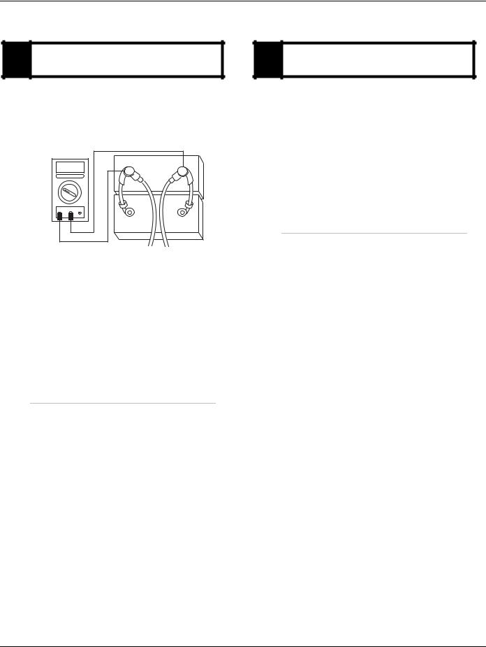
A Purpose:batteries. Measure battery voltage, visually inspect
1.Key off.
2.Inspect starter, battery and in-line fuse holder connections for integrity.
3.Measure voltage across batteries.
VOLTS |
|
|
COM |
V |
A |
– |
+ |
– |
+ |
•If voltage is 11–13 volts on a 12-volt system or 22–26 on a 24-volt system, go to Step B.
•If voltage is outside of range, repair or replace batteries and charging system as required. Then measure voltage again.
B Purpose: Verify the batteries pass a load test.
1.Key off.
2.Load test the Batteries.
•If the batteries maintain the specified load, test complete.
•If the batteries fail the Load Test, replace the damaged battery(s). Go to Step A.
2013.07.17 |
© 2013 Eaton. All rights reserved |
17 |

Power-Up Sequence Pretest | Electrical Pretest Procedure |
TRTS0062 |
Power-Up Sequence Pretest
Overview
A failure during the self-check indicates a failure of the Shift
Controller.
Detection
The power-up self-check is performed automatically each time the key is turned on. Turn the key on and watch the Service light. If power up stops with the Service light constantly on, or it never comes on, self-check has failed.
Fallback
If self-check fails, the product cannot perform any operations.
Possible Causes
This test can be used for the following:
•Shift Controller
•Vehicle Harness
Additional Tools
•Basic hand tools
•Eaton Test Adapter kit
•Digital volt/ohm meter
18 |
© 2013 Eaton. All rights reserved |
2013.07.17 |
TRTS0062 |
Electrical Pretest Procedure | Power-Up Sequence Pretest |
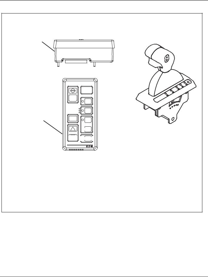
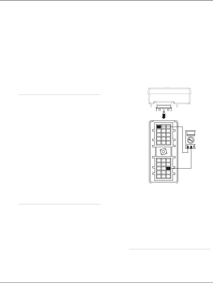
Component Identification
Side view of pushbutton shift control
Transmission controller  30-way connector
|
VOLUME |
|
|
CONTROL |
R |
Top view |
|
|
|
|
|
of pushbutton |
|
N |
shift control |
SERVICE |
D |
|
|
 H
H
SHIFT


 L
L 


Eaton Fuller
Transmissions
Pushbutton Shift Control Eaton Shift Lever
2013.07.17 |
© 2013 Eaton. All rights reserved |
19 |
Power-Up Sequence Pretest | Electrical Pretest Procedure |
TRTS0062 |
Power-Up Sequence Pretest
|
A |
Purpose: Visually identify if the vehicle is equipped |
|
with a Shift Lever. |
|
|
|
|
1.Is vehicle equipped with a Shift Lever?
•If vehicle is not equipped with a Shift Lever, go to Step B.
•If vehicle is equipped with a Shift Lever, go to
Step D.
|
B |
Purpose: Verify proper power up of the transmis- |
|
sion shift controller. |
|
|
|
|
1.Key on.
2.Observe Service light.
Note: If Service light is flashing, see “Diagnostic Procedure” on page 4.
•If Service light lights for one second and turns off, Test complete.
•If Service light never comes on, go to Step C.
•If Service light is on steady, replace Shift Control. Repeat this step.
|
C |
Purpose: Confirm switched ignition voltage to the |
|
transmission shift controller. |
|
|
|
|
1.Key off.
2.Disconnect Shift Controller 30-way connector.
3.Key on.
4.Measure voltage across batteries and record finding.
5.Measure voltage between Shift Controller 30-way Pin C1 and Pin K3.
3 |
1 |
|
|
K |
|
|
|
J |
VOLTS |
|
|
H |
|
||
|
|
|
|
G |
|
|
|
F |
|
|
|
|
V |
COM |
A |
E
D
C
B
A
3 2 1
•If voltage is within 1 volt of battery voltage, replace Shift Control. Go to Step B.
•If voltage is outside of range, no ignition power. Repair ignition power supply to transmission, go to Step B.
20 |
© 2013 Eaton. All rights reserved |
2013.07.17 |

TRTS0062 |
Electrical Pretest Procedure | Power-Up Sequence Pretest |
|
|
|
D |
Purpose: Visually identify if the Shift Lever is an Ea- |
|
ton Shift Lever or an OEM Shift Lever. |
|
|
|
|
1.Is vehicle equipped with an Eaton-supplied Shift Lever or an OEM-supplied Shift Lever?
•If Eaton Shift Lever, go to Step E.
•If OEM Shift Lever, go to Step I.
|
F |
Purpose: Test operation of the transmission Ser- |
|
vice light. |
|
|
|
|
1.Key off.
2.Locate Shift Controller.
3.Disconnect Shift Controller 30-way connector.
4.Place a jumper across Shift Controller 30-way connector Pin J1 and Pin H2.
|
E |
Purpose: Visually observe the Service light during |
|
key-on power up. |
|
|
|
|
1.Key on.
2.Observe Service light.
Note: If Service light is flashing, see “Diagnostic Procedure” on page 4.
•If Service light illuminates for one second and turns off, test complete.
•If Service light never comes on, go to Step F.
•If Service light is on steady, go to Step H.
3 2 1
K
J
H
G
F
E
D
C
B
A
3 2 1
•If Service light turns on, replace Shift Control. Go to Step E.
•If Service light never comes on, go to Step G.
2013.07.17 |
© 2013 Eaton. All rights reserved |
21 |

Power-Up Sequence Pretest | Electrical Pretest Procedure |
TRTS0062 |
|
|
|
G |
Purpose: Confirm OEM Service light power wire |
|
continuity and test for a short to ground. |
|
|
|
|
1.Key off.
2.Disconnect Shift Lever 8-way connector.
3.Measure resistance between:
-Shift Controller 30-way Pin H2 and Shift Lever 8-way connector Pin 6
-Shift Controller 30-way connector Pin H2 and ground.
H Purpose: Test the transmission Service light.
1.Key on.
2.Locate Shift Controller.
3.Disconnect Shift Controller 30-way connector.
•If Service light turns off, replace Shift Control. Go to Step E.
•If Service light remains on, repair OEM harness as required. Go to Step E.
18
27
36
45
OHMS |
|
|
|
|
|
|
3 |
2 |
1 |
|
|
K |
|
|
V COM |
A |
J |
|
|
|
|
H |
|
|
|
|
G |
|
|
|
|
F |
|
|
E
D
C
B
A
3 2 1
•If resistance between Pin H2 and Pin 6 is 0–0.3 ohms and If resistance between Pin H2 and ground is 10K ohms or open circuit [OL], replace Shift Lever. Go to Step E.
•If any of the above conditions are not met, repair Vehicle Harness between Shift Controller and Shift Lever, go to Step E.
|
I |
lightPurpose: Measure battery voltage to the Service |
|
|
|
1.Key off.
2.Locate Service light connector on Vehicle Harness.
3.Measure voltage across Pin A and Pin B on Service light connector.
4.Key on.
•If voltage is within 2 volts of total battery voltage for 1 second, then 0 volts, test complete.
•If no voltage is measured, go to Step J.
•If voltage is within 2 volts of battery voltage continuously, go to Step K.
22 |
© 2013 Eaton. All rights reserved |
2013.07.17 |

TRTS0062 |
Electrical Pretest Procedure | Power-Up Sequence Pretest |
|
|
J Purpose:light Test voltage to the transmission Service
1.Key off.
2.Locate Shift Controller.
3.Disconnect Shift Controller 30-way connector.
4.Place a jumper across Shift Controller 30-way connector Pin J1 and Pin H2.
5.Key on.
6.Measure voltage across Service light connector.
|
K |
Purpose: Measure voltage drop across the OEM |
|
transmission Service light |
|
|
|
|
1.Key on.
2.Locate Shift Controller.
3.Disconnect Shift Controller 30-way connector.
4.Measure voltage across Service Light connector Pin A and Pin B.
|
|
VOLTS |
A |
B |
VCOM |
|
A |
3 1
K
J
H
G
F
E
D
C
B
A
3 2 1
•If voltage is within 2 volts of battery voltage. Replace Shift Control. Go to Step I.
•If no voltage is measured, repair Vehicle Harness as required. Go to Step I.
•If no voltage is measured, replace Shift Control. Go to Step I.
•If voltage is within 2 volts of battery voltage, repair Vehicle Harness as required. Go to Step
I.
2013.07.17 |
© 2013 Eaton. All rights reserved |
23 |

Air Pretest | Electrical Pretest Procedure |
TRTS0062 |
Air Pretest
Overview
The pretest does not relate to any specific fault code, but must be completed before performing “Fault Code Isolation Table” procedures. The pretest verifies that the basic air input is OK before testing individual system functions.
Detection
There is no detection process specifically for the basic air supply; however, failures of this type are generally detected by the transmission or operator as some other type of fault code or symptom.
Fallback
There is no fallback mode for air pretest; however, it may affect other systems.
Possible Causes
This pretest can be used for any of the following:
•Low air pressure
•Contaminated air
•Air Filter-Regulator
Additional Tools
•Basic hand tools
•0-100 PSI Air pressure gauge
24 |
© 2013 Eaton. All rights reserved |
2013.07.17 |
TRTS0062 |
Electrical Pretest Procedure | Air Pretest |
Component Identification
Air filter/regulator
2013.07.17 |
© 2013 Eaton. All rights reserved |
25 |
 Loading...