


Service Manual
Fuller Mid-Range Transmissions
TRSM0130
October 2007
FS-4005A
FS-4005B
FS-4005C
FS-4205A
FS-4205B
FS-4205C
FS-5005A
FS-5005B
FS-5005C

For parts or service call us Pro Gear & Transmission, Inc.
1(877) 776-4600
(407)872-1901 parts@eprogear.com
906 W. Gore St. Orlando, FL 32805

A WARNING
Before starting a vehicle always be seated in the drivers seat, place the transmission in neutral, set the parking brakes and disengage the clutch.
Before working on a vehicle place the transmission in neutral, set the parking brakes and block the wheels.
Before towing the vehicle place the transmission in neutral, and lift the rear wheels off the ground or disconnect the driveline to avoid damage to the transmission during towing.

TABLE OF CONTENTS
FOREWORD ................................................................ |
2 |
MODEL DESIGNATIONS AND SPECIFICATIONS .................................. |
3 |
LUBRICATION ............................................................... |
4 |
OPERATION ................................................................ |
6 |
POWER FLOW ............................................................... |
7 |
TORQUE RECOMMENDATIONS ................................................ |
8 |
PREVENTIVE MAINTENANCE ................................................. |
10 |
PRECAUTIONS |
|
DISASSEMBLY ............................................................ |
12 |
INSPECTION .............................................................. |
12 |
REASSEMBLY ............................................................. |
14 |
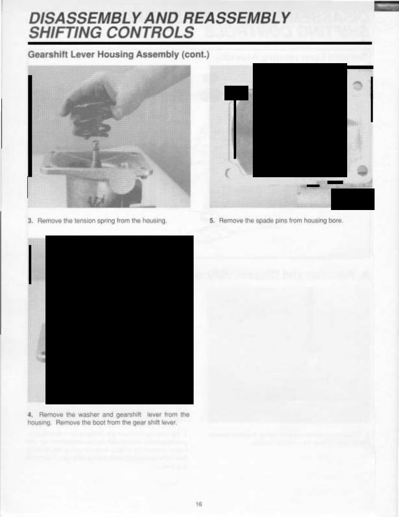
DISASSEMBLY AND REASSEMBLY - SHIFTING CONTROLS |
|
GEARSHIFT LEVER HOUSING ASSEMBLY ....................................... |
15 |
SHIFT BAR HOUSING ASSEMBLY .............................................. |
18 |
REMOVAL - YOKE AND CLUTCH HOUSING ..................................... |
27 |
DISASSEMBLY -TRANSMISSION .............................................. |
29 |
REASSEMBLY - TRANSMISSION .............................................. |
43 |
INSTALLATIONCLUTCH HOUSING ........................................... |
57 |
INSTALLATION - SHIFTING CONTROLS ........................................ |
58 |
OPTIONS .................................................................. |
59 |

FOREWORD
This manual is designed to provide detailed information necessary to service and repair the Eaton@ Fuller@ Transmission listed on the cover.
As outlined in the Table of Contents, the manual is divided into 3 main sections:
a.Technical information and reference
b.Removal, disassembly, reassembly, and installation
c.Options
The format of the manual is designed to be followed in its entirety if complete disassembly and reassembly of the transmission is necessary. But if only one component of the transmission needs to be repaired, see the Table of Contents for the page numbers showing that component. For example, if you need to work on the Shifting Controls, you will find instructions for removal,
disassembly, and reassembly on page 15. Instructions for installation are on page 58. Service Manuals, Illustrated Parts Lists, Drivers Instructions, and other forms of product service information for these and other Eaton Fuller Transmissions are available upon request. A Product Literature Order Form, Service Bulletins (detailing information on product improvements), repair procedures, and other service-related subjects can be obtained by writing to the following address:
EATON CORPORATION TRANSMISSION DIVISION
Technical Service Department P.O. Box 4013
Kalamazoo, Michigan 49003 (616) 342-3344
Every effort has been made to ensure the accuracy of all information in this brochure. However, Eaton Transmission Division makes no expressed or implied warranty or representation based on the enclosed information.
Any errors or omissions may be reported to Training and Publications, Eaton Transmission Division, P.O. Box 4013, Kalamazoo, Ml 49003.
2

|
MODEL |
DESIGNATIONS |
|
|
|
|
|
|
|
|
|
|
|
|
|
|
|||||||||||||||||||
|
AND |
SPECIFICATIONS |
|
|
|
|
|
|
|
|
|
|
|
|
|
|
|
|
|||||||||||||||||
|
|
|
|
|
|
|
|
|
|
|
|
|
|
|
|
|
|
|
|
|
|
|
|
|
|
|
|
|
|
|
|
|
|
|
|
|
Nomenclature: |
|
|
|
F S- 5005A |
|
|
|
|
|
|
|
|
|
|
|
|
||||||||||||||||||
|
|
|
|
|
|
|
|
|
|
|
|
|
|
|
Number Designations |
|
|
||||||||||||||||||
|
|
|
|
|
|
|
|
|
|
|
|
|
|
|
|
|
|
|
|
|
|
|
|
|
|
|
|
|
|||||||
|
Letter Designations |
|
|
|
|
|
|
|
|
|
|
|
|
|
I |
|
|
|
Ratio Group |
|
|
|
|
|
|
||||||||||
|
|
|
|
|
|
|
|
|
|
|
|
|
|
|
|
|
|
|
|
|
|
|
|||||||||||||
|
|
|
|
|
|
|
|
|
|
|
|
I |
|
|
|
|
|
|
|
|
|
|
|
|
|
|
|
|
|
|
|||||
|
Fuller"' |
|
|
|
|
|
|
|
|
|
|
|
|
|
|
|
|
|
|
|
|
|
Forward Speeds |
|
|
||||||||||
|
|
|
|
|
|
|
|
|
|
|
|
|
|
|
|
|
|
|
|
|
|
|
|
||||||||||||
|
|
|
|
|
|
|
|
|
|
|
|
|
|
|
|
|
|
|
|
|
|
|
|
|
Design Level |
|
|
||||||||
Synchronized----------""""' |
|
|
|
|
|
|
|
|
|
|
|
|
|
|
|||||||||||||||||||||
|
|
|
|
|
|
|
|
|
|
|
|
|
|
||||||||||||||||||||||
|
|
|
|
|
|
|
|
|
|
|
|
x 100 =Nominal Torque |
|||||||||||||||||||||||
|
|
|
|
|
|
|
|
|
|
|
|
|
|
|
|
|
|
|
|
|
|
|
|
|
|
|
|||||||||
|
|
|
|
|
|
|
|
|
|
|
|
|
|
|
|
|
|
|
|
|
|
|
|
|
|
|
|||||||||
|
|
|
|
|
|
|
|
|
|
|
|
|
|
|
|
|
|
|
|
|
|
|
|
|
|
|
Capacity |
|
|
|
|
|
|
||
|
|
|
|
|
|
|
|
|
|
|
|
|
|
|
|
|
|
|
|
|
|
|
|
|
|
|
|
|
|
||||||
|
|
|
|
|
|
|
|
|
|
|
|
|
|
|
|
|
|
|
|
IMPORTANT: All Eaton Fuller Transmissions are |
|||||||||||||||
|
|
|
|
|
|
|
|
|
|
|
|
|
|
|
|
|
|
|
|
identified by the model and serial number. This |
|||||||||||||||
|
|
|
|
|
|
|
|
|
|
|
|
|
|
|
|
|
|
|
|
information is stamped on the transmission identifi- |
|||||||||||||||
|
|
|
|
|
|
|
|
|
|
|
|
|
|
|
|
|
|
|
|
cation tag and affixed to the case. |
|
|
|
|
|
|
|||||||||
|
|
|
|
|
|
|
|
|
|
|
|
|
|
|
|
|
|
|
|
DO NOT REMOVE OR DESTROY THE TRANSMIS- |
|||||||||||||||
|
|
|
|
|
|
|
|
|
|
|
|
|
|
|
|
|
|
|
|
SION IDENTIFICATION TAG. |
|
|
|
|
|
|
|||||||||
|
Specifications: |
|
|
|
|
|
|
|
|
|
|
|
|
|
|
|
|
|
|
|
|
|
|
|
|
|
|
|
|||||||
|
|
|
|
|
|
|
|
|
|
|
|
|
|
|
|
|
|
|
|
|
|
|
|
|
|
|
|
||||||||
|
|
|
|
|
|
|
|
|
|
|
|
|
|
|
|
|
|
|
|
|
|
|
|
|
|
|
|
|
|
|
|
|
|
||
|
|
|
|
|
|
|
|
|
|
|
|
|
|
|
|
|
|
|
|
|
|
|
Reial ve Soeed |
|
No:c · |
|
~ote 2 |
|
Note S |
||||||
|
|
|
|
|
|
|
|
|
|
|
|
|
|
|
|
|
|
|
|
|
|
|
|
|
|
|
|||||||||
|
|
|
|
|
|
|
|
|
|
|
|
GearRat'os |
|
|
|
|
|
|
|
PTO 3ear::: |
|
_e-g111 |
|
l//eo': |
|
Q,I Caoaci:y |
|||||||||
|
|
|
|
|
Ne. |
|
|
|
|
|
|
|
|
|
|
|
|
|
|
|
lnpc: R.P.~A. |
|
ir. |
|
Los. |
|
Pi-ts |
||||||||
|
Model |
Speecs |
|
|
1 st |
2 nc |
3 ·a |
|
4th |
5 '.1 |
|
|
Rf:'ver:;e |
Rigrt |
Li:/t |
|
'"1:'1) |
|
:Kg) |
|
1Uersi |
||||||||||||||
|
|
|
|
|
|
|
|
|
|
|
|
|
|
||||||||||||||||||||||
|
|
|
|
|
|
|
|
|
|
|
|
|
|
|
|
|
|
|
|
|
|
|
|
|
|
||||||||||
|
FS-5005A |
5 |
|
|
|
7.52 |
|
2.54 |
2.54 |
|
1.52 |
1.00 |
|
|
6.27 |
.460 |
.435 |
21.9 |
|
280 |
|
|
|
10.5 |
|
||||||||||
|
|
|
|
|
|
|
|
|
|
|
|
|
|
|
|
|
|
|
|
|
|
|
|
|
|
|
(556.0) |
|
(127.0) |
|
|
|
(5.0} |
|
|
|
|
|
|
|
|
|
|
|
|
|
|
|
|
|
|
|
|
|
|
|
|
|
|
|
|
|
|
|
|
|
|
|
|
|
|
|
FS-50058 |
5 |
|
|
|
6.82 |
|
2.15 |
2.15 |
|
1.28 |
1.00 |
|
|
5.30 |
.543 |
.515 |
21.9 |
|
280 |
|
|
|
10.5 |
|
||||||||||
|
|
|
|
|
|
|
|
|
|
|
|
|
|||||||||||||||||||||||
|
|
|
|
|
|
|
|
|
|
|
|
|
|
|
|
|
|
|
|
|
|
|
|
|
|
|
(556.0) |
|
(127.0} |
|
|
|
(5.0) |
|
|
|
FS-5005C |
5 |
|
|
|
6.82 |
|
1.99 |
1.99 |
|
1.17 |
1.00 |
|
|
5.30 |
.543 |
.515 |
21.9 |
|
280 |
|
|
|
10.5 |
|
||||||||||
|
|
|
|
|
|
|
|
|
|
|
|
|
|||||||||||||||||||||||
|
|
|
|
|
|
|
|
|
|
|
|
|
|
|
|
|
|
|
|
|
|
|
|
|
|
|
(556.0) |
|
(127.0) |
|
|
|
(5.0} |
|
|
|
|
|
|
|
|
|
|
|
|
|
|
|
|
|
|
|
|
|
|
|
|
|
|
|
|
|
|
|
|
|
|
|
|
|
|
1.Lengths measured from clutch housing face to speedo gear rear.
2.Weights include shift bar housing, clutch housing, less tower assembly, and clutch release parts. For more information on available clutch housings, see the transmission'sIllustrated Parts List or the Super Parts Book. All weights are approximate.
3.Oil capacities are approximate, depending on inclination of engine and transmission. Always fill transmission, with proper grade and type of lubricant, to level of filler opening. See LUBRICATION.
3

-
LUBRICATION
Proper Lubrication . ..
the Key to long transmission life
Proper lubrication procedures are the key to a good allaround maintenance program. If the oil is not doing its job, or if the oil level is ignored, all the maintenance procedures in the world are not going to keep the transmission running or assure long transmission life.
Eaton Fuller Transmissions are designed so that the internal parts operate in an oil circulating bath by the motion of the gears and shafts.
Thus, all parts are amply lubricated if these procedures are closely followed:
1.Maintain oil level. Inspect regularly.
2.Change oil regularly.
3.Use the correct grade and type of oil.
4.Buy from a reputable dealer.
Lubrication Change and Inspection
HIGHWAY USE
|
|
Firs'3,000 tc 5,000 miles |
|
|
|
|
|
|
Factory fill |
||||
|
|
{4827 to 8045 Km! |
|
|
|
|
|
|
1rn:ia o·ai:-:. |
||||
|
|
|
|
|
|
|
|
|
|
|
|
|
|
|
|
Every t0,000 miles |
|
|
|
|
|
Check flukl level. |
|||||
|
|
(;6090 Ker) |
|
|
|
|
|
|
Check ::::r iea;.;s. |
||||
|
|
Every 250,000 m•les |
|
|
|
|
|
Craoge t•ans'.'1•sso1 |
|||||
|
|
(402336 Krr) |
|
|
|
|
|
|
|
llu·d. |
|||
|
|
|
|
OFF-HIGHWAY USE |
|
|
|
|
|
||||
|
|
Firs~ 30 hour_; |
|
|
|
|
|
|
|
Factory f I |
|
||
|
|
|
|
|
|
|
|
initial d·ain. |
|||||
|
|
|
|
|
|
|
|
|
|
||||
|
|
Every 40 hours |
|
|
lnspec: fluic |
eve!. Creek fa• leaks. |
|||||||
|
|
|
|
|
|
|
|
|
|||||
|
|
Every 500 hours |
|
|
|
Criange tra."sriission 71uic where |
|
||||||
|
|
|
|
|
|
severe dirt :::onditions exist. |
|
||||||
|
|
|
|
|
|
|
|
||||||
|
|
Every t .:O·Joours |
|
|
|
|
Cra1ge trans11·ss.0°lluid |
||||||
|
|
|
|
|
|
(Norrra: off-h ahway cse." |
|
||||||
|
|
|
|
|
|
|
|
||||||
|
|
|
Heavy Duty Engine Lubricant or |
||||||||||
|
|
|
|
Mineral Gear Lubricant |
|
|
|
|
|
||||
|
|
|
|
HIGHWAY USE |
|
|
|
|
|
||||
|
|
|
|
|
|
|
|
|
|
|
|
||
|
|
First 3.000 to 5,COO riiles |
|
|
|
|
|
|
Fac:oryiill |
||||
|
|
I4827 to 8045 Krr I |
|
|
|
|
|
|
|
imtial. |
|||
|
|
|
|
|
|
|
|
|
|
||||
|
|
Every 10,000 -;iles |
|
|
|
|
|
l'isoec:lubrica'ltlevel. |
|||||
|
|
(t6090 ~rr• |
|
|
|
|
|
|
C1eck :or ·eal{s. |
||||
|
|
|
|
|
|
|
|
|
|
|
|||
|
|
Every 50.000 11 les |
|
|
|
|
|
Cha1ge tra:isr:i1ss1on |
|||||
|
(80450) |
|
|
|
|
|
|
|
|
lubr•car:. |
|||
|
|
|
|
|
|
|
|
|
|||||
|
|
|
|
|
|
|
|
|
|
||||
|
|
|
|
OFF-HIGHWAY USE |
|
|
|
|
|
||||
|
|
First 3·J oours |
|
|
|
|
|
Cnange transrr:issio-; |
|
||||
|
|
|
|
|
|
lubricant en new :.inits. |
|||||||
|
|
|
|
|
|
|
|
||||||
|
|
|
|
|
|
|
|||||||
|
|
Every 40 1purs |
|
|
lr.soect lubricaPt 1 |
eve~. Chee!\ br 1eaks. |
|
||||||
|
c~.a:ige transmissior. lubr:cant where |
|
Eaton® Roadranger® CDSO Transmission Fluid |
||
Every 500 rours |
sevee di~ condit:ons exist. |
|
|
||
|
|
|
Every 1,00C hoers |
Change 'ransmissionlubricant |
|
(Norma: off-h:ghway t.se.] |
||
|
||
Recommended Lubricants
|
|
Fahrenheit (Celsius) |
Type |
Grade |
Ambient |
(SAE) |
Temperature |
Eaton@Roadranger(<, |
|
|
|
CDSO Transmission |
50 |
All |
|
Fluid |
|||
|
|
||
Heavy Duly E.0 .gine Oi |
|
|
|
MIL-L-21048, Cor Dor |
50 |
Above 10'F(-t2'C) |
|
APl-SF 0'AP:-CD |
40 |
Above 10"F (·12"C; |
|
(Pr9ViOJS API des1gna~io1s |
30 |
Below 10'F:-12''C) |
|
acceotab e1 |
|
|
|
|
|
|
|
Mneral Gear OI' w'.hrust |
90 |
Abo'e1JF i- '.2'·C) |
|
and oxi:::a~ion i'":hibitor |
sew |
Below 'O'Fi-"2'C) |
ft.Pl-GL-'.
The use of mild EP gear oil or multi-purpose gear oil is not recommended, but ifthesegearoilsare used, be sure to adhere to the following limitations.
Do not use mild EP gear oil or multi-purpose gear oil when operating temperatures are above 230° F (110" C). Many of these gear oils, particularly 85W140, break down above 230° F and coat seals, bearings, and gears with deposits that can cause premature failures. If these deposits are observed (especially a coating on seal areas causing oil leakage), change to Eaton Roadranger CD50 transmission fluid, heavy duty engine oil, or mineral gear oil to assure maximum component life and to maintain your warranty with Eaton. (Also see "Operating Temperatures".)
Additives and friction modifiers are not recommended for use in Eaton Fuller Transmissions.
Proper Oil Level
Proper Oil Level
Make sure oil is level with the filler opening. Because you can reach oil with your finger does not mean oil is at proper level. (One inch of oil level is about one gallon of oil.)
Draining Oil
Drain transmission while oil is warm. To drain oil remove the drain plug at case bottom. Clean the drain plug before re-installing.
Refilling
Clean case around filler plug and remove plug from case side. Fill the transmission to the level of the filler opening. If the transmission has two filler openings, fill to the level of both openings.
The exact amount of oil depends on the transmission inclination and model. Do not over fill-this causes oil to be forced out of the case through the front bearing cover.
When adding oil, types and brands of oil should not be mixed because of possible incompatibility.
4

LUBRICATION
Operating Temperatures
-With Eaton Roadranger
CDSO Transmission Fluid
Heavy Duty Engine Oil
and Mineral Oil
The transmission should not be operated consistently at temperatures above 250° F (120° C}. However, intermittent operating temperatures to 300° F (149° C} do not harm the transmission. Operating temperatures above 250° F increase the lubricant'soxidation rate and shorten its effective life. When the average operating temperature is above 250° F, the transmission can require more frequent oil changes or external cooling.
The following conditions in any combination can cause operating temperatures of over 250° F: (1 )operating consistently at slow speeds, (2) high ambient temperatures, (3) restricted air flow around transmission, (4) exhaust system too close to transmission, (5) high horsepower, overdrive operation.
External oil coolers are available to reduce operating temperatures when the above conditions are encountered.
Transmission Oil Coolers are:
Recommended
-With engines of 350 H.P. and above with overdrive transmissions
Required
-With engines 399 H.P. and above with over drive transmissions and GCW'sover 90,000 lbs.
-With engines 399 H.P. and above and 1400 lbs-ft or greater torque
-With engines 450 H.P. and above
With EP or Multipurpose Gear Oil
Mild EP gear oil and multipurpose gear oil are not recommended when lubricant operating temperatures are above 230° F (110° C). In addition, transmission oil coolers are not recommended with these gear oils since the oil cooler materials can be attacked by these gear oils. The lower temperature limit and oil cooler restriction with these gear oils generally limit their success to milder applications.
Proper Lubrication Levels as Related to Transmission Operating Angles
If the transmission operating angle is more than 12 degrees, improper lubrication can occur. The operating angle is the transmission mounting angle in the chassis plus the percent of upgrade (expressed in degrees).
The chart below illustrates the safe percent of upgrade on which the transmission can be used with various chassis mounting angles. For example: if you have a 4 degree transmission mounting angle, then 8 degrees (or 14 percent of grade) is equal to the limit of 12 degrees. If you have a 0 degree mounting angle, the transmission can be operated on a 12 degree (21 percent} grade.
Anytime the transmission operating angle or 12 degrees is exceeded for an extended period of time the transmission should be equpped with an oil pump or cooler kit to insure proper lubrication.
Note on the chart the effect low oil levels can have on safe operating angles. Allowing the oil level to fall 1/2" below the filler plug hole reduces the degree of grade by approximately 3 degrees (5.5 percent}.
Proper Lubrication Levels are Essential!
2 t---+--l--+--+--l---1---1 1 8'
0 |
|
|
|
|
0 |
0 |
2 |
3 |
4 |
5 |
67 |
Transmission Mounting Angle
Dotted line showing "2 Quarts Low" is for reference only. Not recommended
5

OPERATION
Gear Shift Lever Pattern and
Shifting Instructions
Follow the simple 5-speed shift pattern. ..
Simple progressive shift pattern
-,\
R 2
"-·-1/ I
I
-,
1
J
··--"
\,__..__)
Neutral
I .,
3 I
j
/
Adobe 0001-2/88
(-- -,
i
4
I\ ,_____ /j
] ___'
( |
\ |
5
\ ..____. /J
R |
2H• |
4H |
|
|
2L i |
4L |
, |
||
|
||||
<__; \... I ./ |
. |
,; |
||
-Ne~tral --j
- 1H .,, |
1(-3H -,i ,-- s -,I |
||
1 |
|
|
|
1 1L , |
|
3L |
· |
\__ __) "·- |
|
: <_ _; |
|
FS-SOOSB with "soft" fourth and 2-speed axle.
( -- \ I . \
|
R |
I |
2H. |
I |
4H' |
|
I |
2L |
: 4L |
||
|
_) |
||||
\,_ |
\ .. _ . ) "" |
_) |
|||
~- Neutral |
-1 |
||||
/-~\ |
(-- : -..\ |
(,,.- |
·-,, |
||
, 1H , |
|
3H , |
, |
SH j |
|
1L |
|
3L |
,__ |
SL ! |
|
\,_ |
__/ |
\ ___ _.) |
- |
||
FS-5005C with "short" fourth and 2-speed axle.
General Information
FS-5005 transmissions have five forward speeds and one reverse, and are shifted as you would shift any synchronized manual transmission, following the simple 5-speed shift pattern.
Driving Tips
•Always use the clutch when making upshifts or downshifts. Premature synchronizer failure can result from not using the clutch.
• Always select a starting gear that provides sufficient reduction for the load and terrian.
•Never downshift at road speed too high.
•Never slam or jerk the shift lever to complete gear engagement.
•Never coast with the transmission in neutral and the clutch dis-engaged.
6

POWER FLOW
The transmission must efficiently transfer the engine'spower, in terms of torque, to the vehicle'srear wheels. Knowledge of whattakes place in the transmission during torque transfer is essential when troubleshooting and making repairs.
1.Power (torque) from the engine is transferred to the input shaft and drive gear.
2.Torque is transferred to the countershaft drive gear.
3.Torque is delivered along the countershaft to all countershaft gears.
4.Torque is transferred to "engaged" mains haft gear. The cross section illustrates 1st speed gear position.
5.Engaged mainshaft gear internal clutching teeth transfers torque to mainshaft through synchronizer assembly.
6.Mainshaft transfers torque directly to driveshaft through rear yoke.
1.
5.
3. |
4. |
7
TORQUE RECOMMENDATIONS
Correct torque application is important to assure long transmission life. Over or under tightening of fasteners can resul1 in a loose installation and, in many instances, can eventually cause damage to the transmission. Use a torque wrench to obtain recommended torque ratings. Do not torque capscrews dry.
4 FRONT BEARING COVER CAPSCREWS 15-20 LBS.-FT. 5/16-18 THREAD
4 SHIFT LEVER HOUSING |
9 SHIFT RAIL RETAINER |
CAPSCREWS |
CAPSCREWS |
20-25 LBS.-FT. |
20-25 LBS.-FT. |
3/8-16 THREAD |
3/8-16 THREAD |
17 SHIFT BAR HOUSING CAPSCREWS
20-25 LBS.-FT.
3/8-16 THREAD
@
4 CLUTCH HOUSING CAPSCREWS 145-155 LBS.-FT. 5/8-16 THREAD
2 HAND HOLE COVER CAPSCREWS 5 LBS.-FT.
1/4-12 THREAD
OUTPUT SHAFT NUT 300-350 LBS.-FT. 11/4-18 THREAD WITH
NYLON LOCKING INSERT (OILED AT VEHICLE INSTALLATION)
Adobe 0002-2/88
8

TORQUE RECOMMENDATIONS
4 MAINSHAFT REAR BEARING COVER NUTS
60-70 LBS.-FT.
1/2-32 THREAD
USE LOCKWASHERS
|
|
|
OIL FILL PLUG |
|
|
|
20-25 LBS.-FT. |
|
|
|
3/4 PIPE THREAD |
|
14 PTO COVER |
|
|
|
CAPSCREWS |
|
2 COUNTERSHAFT REAR |
|
10-15 LBS.-FT. |
|
|
|
|
BEARING CAP SET SCREWS |
|
|
3/8-16 THREADS |
|
|
|
|
5-10 LBS.-FT. |
|
|
|
|
|
|
|
|
1/4 THREAD |
|
4 COUTNERSHAFT REAR BEARING |
OIL DRAIN PLUG |
|
|
COVER CAPSCREWS |
||
|
20-25 LBS.-FT. |
||
|
20-30 LBS.-FT. |
||
|
3/4 |
PIPE THREAD |
|
|
3/8-16 THREAD |
||
|
|
|
|
|
USE PLAIN FLAT WASHERS |
|
|
|
|
NOTE: APPLY LOCTITE #262 TO THREADS OF |
|
- |
Adobe 0003-2/88 |
ALL CAPSCREWS BEFORE INSTALLING. |
|
|
|
||
|
|
|
|
|
9 |
|
|
|
|
|
|

PREVENTIVE MAINTENANCE
10

PREVENTIVE MAINTENANCE
Preventive Maintenance Check Chart
CHECKS WITHOUT PARTIAL DISASSEMBLY OF CHASSIS OR CAB
1.Clutch Housing Mounting
a.Check all capscrews of clutch housing flange for looseness.
2.Clutch Release Bearing (Not Shown)
a.Remove hand hole cover and check radial and axial clearance in release bearing.
b.Check relative position of thrust surface of release bearing with thrust sleeve on pushtype clutches.
3.Clutch Pedal Shaft and Bores
a.Pry upward on shafts to check wear.
b.If excessive movement is found, remove clutch release mechanism and check bushings in bores and wear on shafts.
4.Lubricant
a.Change at specified service intervals.
b.Use only the types and grades as recommended. See LUBRICATION.
5.Filler and Drain Plugs
a.Remove filler plug and check level of lubricant at specified intervals. Tighten filler and drain plugs securely.
6.Capscrews and Gaskets
a.Check all capscrews, especially those on PTO covers, front and rear bearing covers for looseness which can cause oil leakage.
See TORQUE RECOMMENDATIONS.
b.Check PTO opening and rear bearing covers for oil leakage.
8.Gear Shift Lever Housing Assembly
a.Remove the gear shift lever housing assembly from transmission.
b.Check tension spring and washer for set and wear.
c.Check gear shift lever bottom end for wear of slots. Also check finger assembly for wear.
CHECKS WITH DRIVE LINE DROPPED
9.Universal Joint Companion Flange or Yoke Nut
a.Check for tightness. Tighten to recommended torque rating.
10.Output Shaft (Not Shown)
a.Pry upward against output shaft to check radial clearance in mainshaft rear bearing.
CHECKS WITH UNIVERSAL JOINT COMPANION FLANGE OR YOKE REMOVED
NOTE: If necessary, use solvent and shop rag to clean sealing surface of companion flange or yoke. DO NOT USE CROCUS CLOTH,
EMERY PAPER, OR OTHER ABRASIVE MATERIALS THAT WILL MAR SURFACE FINISH.
11.Splines on Output Shaft (Not Shown)
a.Check for wear from movement and chucking action of the universal joint companion flange or yoke.
7.Gear Shift Lever
a.Check for looseness and free play in housing. If lever is loose in housing, proceed with Check No. 8.
12.Mainshaft Rear Bearing Cover
a.Check oil seal for wear.
- |
11 |
|

-
PRECAUTIONS
Disassembly
It is assumed in the detailed assembly instructions that the lubricant has been drained from the transmission, the necessary linkage disconnected and the transmission has been removed from vehicle chassis. Removal of the gear shift lever housing assembly is included in the detailed instructions (Disassembly and Reassembly-Shifting Controls); however, this assembly must be detached from shift bar housing before transmission can be removed.
FOLLOW CLOSELY EACH PROCEDURE IN THE DETAILED INSTRUCTIONS, MAKING USE OF THE TEXT, ILLUSTRATIONS, AND PHOTOGRAPHS PROVIDED.
1.BEARINGS-Carefully wash and relubricate all reuseable bearings as removed and protectively wrapped until ready for use. Remove bearings planned to be reused with pullers designed for this purpose.
2.ASSEMBLIES-When disassembling the various assemblies, such as the mainshaft, countershafts, and shift bar housing, lay all parts on a clean bench in the same order as removed. This procedure simplifies reassembly and reduces the possibility of losing parts.
3.SNAP RINGS-Remove snap rings with pliers designed for this purpose. Snap rings removed in this manner can be reused, if they are not sprung or loose.
4.CLEANLINESS-Provide a clean place to work. It is important that no dirt or foreign material enters the unit during repairs. Dirt is an abrasive and can damage bearings. It is always good practice to clean the outside of the unit before starting the planned disassembly.
5.WHEN USING TOOLS TO MOVE PARTS-
Always apply force to shafts, housings, etc, with restraint. Movement of some parts is restricted. Never apply force to the part being driven after it stops solidly. The use of soft hammers, bar, and mauls for all disassembly work is recommended.
Inspection
Before reassembling the transmission, check each part carefully for abnormal or excessive wear and damage to determine reuse or replacement. When replacement is necessary, use only genuine Eaton Fuller Transmission parts to assure continued performance and extended lite from your unit.
Since the cost of a new part is generally a small fraction of the total cost of downtime and labor, avoid reusing a questionable part which could lead to additional repairs and expense soon after reassembly. To aid in determining the reuse or replacement of any transmission part, consideration should also be given to the unit'shistory, mileage, application, etc.
Recommended inspection procedures are provided in the following checklist.
A. BEARINGS |
B. GEARS |
1.Wash all bearings in clean solvent. Check balls, rollers, and raceways for pitting, discoloration, and spalled areas. Replace bearings that are pitted, discolored, spalled, or damaged during disassembly.
2.Lubricate bearings that are not pitted, discolored, or spalled and check for axial and radial clearances.
Replace bearings with excessive clearances.
3.Check bearing fit. Bearing inner races should be tight to shaft; outer races slightly tight to slightly loose in case bore. If bearing spins freely in bore, case should be replaced.
1.Check gear teeth for frosting and pitting. Frosting of gear teeth faces present no threat of transmission failure. Often in continued operation of the unit, frosted gears "heal" and do not progress to the pitting stage. In most cases, gears with light to moderate pitted teeth have considerable gear life remaining and can be reused, but gears with advanced stage pitting should be replaced.
2.Check for gears with clutching teeth abnormally worn, tapered, or reduced in length from clashing in shifting. Replace gears found in any of these conditions.
12

PRECAUTIONS
Inspection (cont.)
3.Check axial clearance of gears. Where excessive clearance is found, check gear snap ring, split washer, clutch hub, and gear hub for excessive wear.
C.SPLINES
1.Check splines on all shafts for abnormal wear. If sliding clutch gears, companion flange, or clutch hub have worn into the sides of the splines, replace the specific shaft affected.
D.WASHERS
1.Check surfaces of all washers. Washers scored or reduced in thickness should be replaced.
E.REVERSE IDLER GEAR ASSEMBLIES
1.Check for excessive wear from action of roller bearings.
F.GRAY IRON PARTS
1.Check all gray iron parts tor cracks and breaks. Replace or repair parts found to be damaged. Heavy castings may be welded or brazed provided the cracks do not extend into the bearing bores or bolting surfaces. When welding, never place the ground so current passes through the transmission.
G.CLUTCH RELEASE PARTS
1.Check clutch release parts. Replace yokes worn at cam surfaces and bearing carrier worn at contact pads.
2.Check pedal shafts. Replace those worn at bushing surfaces.
H.SHIFT BAR HOUSING ASSEMBLY
1.Check tor wear on shift yokes and finger as sembly at pads and lever slot. Replace excessively worn parts.
2.Check yokes for correct alignment. Replace sprung yokes.
3.Check lockscrews in yoke assembly retainer plates. Tighten those loose.
I.GEAR SHIFT LEVER HOUSING ASSEMBLY
1.Check spring tension on shift lever. Replace tension spring if lever moves too freely.
2.If housing is disassembled, check gear shift lever bottom end and shift finger assembly for wear. Replace both gears if excessively worn.
J.BEARING COVERS
1.Check covers for wear from thrust of adjacent bearing. Replace covers damaged from thrust
of bearing outer race.
2.Check cover bores for wear. Replace those worn oversized.
K.OIL SEALS
1.Check oil seal in input shaft and rear bearing cover. It sealing action of lip has been destroyed, replace seal.
L.SYNCHRON~ERASSEMBLY
1.Check synchronizer for burrs, uneven and excessive wear at contact surface, and metal particles.
2.Check blocker pins for excessive wear or looseness.
3.Check synchronizer contact surfaces on the synchronizer cups for wear.
- |
13 |
|

-
PRECAUTIONS
Reassembly
Make sure that case interiors and housings are clean. It is important that dirt and other foreign materials are kept out of the transmission during reassembly. Dirt is an abrasive and can damage polished surfaces of bearings and washers. Use certain precautions, as listed below, during reassembly.
1.GASKETS-Use new gaskets throughout the transmission as it is being rebuilt. Make sure all gaskets are installed. An omission of any gasket can result in oil leakage or misalignment of bearing covers.
2.CAPSCREWS-To prevent oil leakage and loosening, use Loctite #262 thread sealant on all capscrews. For recommended torque ratings, see TORQUE RECOMMENDATIONS.
3.SHIMS-Apply a light coat of Loctite 51 Oto both
5.INITIAL LUBRICATION-Coat all thrust washers, synchronizers, and bearings with transmission lubricant during reassembly to prevent damage during initial start up.
6.AXIAL CLEARANCES-Maintain original axial clearances for mainshaft gears.
7.BEARINGS-Using a sleeve type driver that contacts the bearing inner race prevents damage to the rollers and cage.
sides of shims before final installation to prevent |
8. UNIVERSAL JOINT COMPANION FLANGE OR |
leakage. |
YOKE-Pull the companion flange or yoke into |
|
place with the output shaft nut, using 300-350 |
4. ASSEMBLY-See the illustrations provided in the |
lbs.-ft. (407-475 Nm) of torque. Make sure the |
detailed disassembly instructions as a guide to |
speed ometer drive gear or a replacement spacer |
reassembly. |
has been installed. Failure to properly torque the |
|
nut can result in damage to the mainshaft rear |
|
bearing. |
IMPORTANT: SEE THE APPROPRIATE ILLUSTRATED PARTS LIST (SPECIFIED BY MODEL SERIES) TO ENSURE THAT PROPER PARTS ARE USED DURING REASSEMBLY OF THE TRANSMISSION.
14


 Loading...