


Service Manual
Fuller Heavy Duty Transmissions
TRSM0503
October 2007
RTX-12510
RTX-12515
RTXF-12510
RTXF-12515

For parts or service call us Pro Gear & Transmission, Inc.
1(877) 776-4600
(407)872-1901 parts@eprogear.com
906 W. Gore St. Orlando, FL 32805

Table of Contents
Model Designations
Description
Specifications
Lubrication
Operation
Air Systems
Preventive Maintenance
Changing Input Shaft
Disassembly Precautions
Disassembly Instructions
I.Shifting Controls
A.Deep Reduction Air System (RT-12515)
B.Range Shift Air System
C.Gear Shift Lever Housing
D.Shift Bar Housing
II. companion Flange, Auxiliary Housing and Clutch Housing
111.Front Section
A.Auxiliary Drive Gear
B.Left Reverse Idler Gear
C.Countershaft Bearings
D.Mainshaft
E.Drive Gear
F.Countershafts
G.Right Reverse Idler Gear
IV. Auxiliary Section –RT-1110 Series
A.Range Shift Cylinder
B.Auxiliary Countershafts
C.Synchronizer
D.Low Speed Gear and Output Shaft V. Auxiliary Section –RT-12510 Series
A.Range Shift Cylinder
B.Auxiliary Counershafts
C.Synchronizer
D.Output Shaft
VI. Auxiliary Section –RT-12515 Series
A.Range Shift Cylinder
B.Auxiliary Counterhafts
C.Synchronizer
D.Low Range Gear and Range Mainshaft
E.Deep Reduction Shift Cylinder
F.Output Shaft
Inspection
Torque Ratings
Reassembly Precautions
Reassembly Instructions
I.Auxiliary Section-RT-1110 Series
A.Output Shaft
B.Synchronizer
C.Auxiliary Countershafts
D.Range Shift Cylinder
II.Auxiliary Section –RT-12510 Series
A.Output Shaft
B.Synchronizer
C.Auxiliary Countershafts
D.Range Shift Cylinder
III.Auxiliary Section –RT-12515 Series
A.Output Shaft
B.Range Mainshaft
C.Deep Reduction Shift Cylinder
D.Low Range Gear
E.Synchronizer
F.Auxiliary Countershafts
G.Range Shift Cylinder
IV. Front Section
A.Right Reverse Idler Gear
B.Countershafts
C.Countershaft Installation
D.Drive Gear
E.Drive Gear Installation
F.Left Countershaft Timing Mainshaft Axial Clearances
G.Mainshaft
H.Mainshaft Installation
I.Left Reverse Idler Gear
J.Mainshaft Final Installation
K.Auxiliary Drive Gear
V. Companion Flange, Auxiliary Housing and
Clutch Housing
VI. Shifting Controls
A.Shift Bar Housing
B.Gear Shift Lever Housing
C.Air System
Tool Reference
2
|
|
Model |
Designations |
|
|
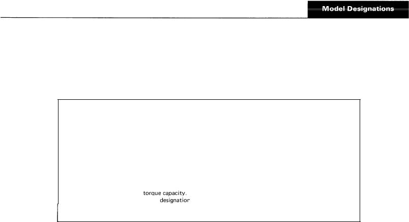
R T - l l l O – |
|
Roadranger transmission, |
twin countershaft, 10 |
speeds, 1100 |
lbs./ft. torque capacity. |
RTO-1 110 |
–- Roadranger transmission, twin countershaft, 10 |
speeds, including an overdrive ratio, |
|||
|
|
1100 Ibs.-ft, torque capacity. |
|
|
|
RT-12510 – Roadranger transmission, |
twin countershaft, 10 |
speeds, 1250 |
lbs./ft. torque capacity. |
||
RTO-12510 |
– |
Roadranger transmission, |
twin countershaft, 10 speeds, including an overdrive ratio, |
||
1250 Ibs.-ft. torque capacity.
RT-12515 – Roadranger transmission, twin countershaft, 15 speeds, 1250 lbs./ft. torque capacity
RTO-1 2515 – Roadranger |
transmission, twin countershaft, 15 speeds, including an overdrive ratio, |
||
|
1250 Ibs.-ft. |
|
|
“F” – |
Included in |
letter |
before numerals, such as RTF-12510, etc. denotes for- |
ward position of the gear shift lever.
N O T E
Illustrated parts lists with part numbers are available upon request. Write Service Department, Eaton Corporation, Transmission Division, 222 Mosel Avenue, Kalamazoo, Michigan 49007.
3

Description
The RT-111 O and RT-12510 transmissions are designed for heavy-duty on-highway equipment. The twin countershaft design, which splits torque equally between the two shafts, provides a high torque capacity to weight ratio . Because of torque splitting, each gear set carries only half the load, greatly reducing the face width of each gear.
Another unique design feature is the floating gear principle. The mainshaft gears when not engaged “float” between the countershaft gears, eliminating the need for gear sleeves and bushings. All gears are in constant mesh and have spur type teeth.
The RT-111 O and RT-12510 transmissions have ten forward speeds and two reverse, consisting of a five-speed front section and a two-speed auxiliary or range section, both contained in one case. First through fifth speeds are obtained by using the five gear ratios in the front section
through the low speed gear of the range section. Sixth through tenth speeds are obtained by using the five gear ratios in the front section through the high speed (direct drive) range gear. As in other Roadranger transmissions, the ratios are progressively spaced.
The RT-125 15 transmissions have 15 forward speeds and three  consisting of a five-speed front section, which is identical to the RT-1 110 and RT-1251O front section, and a three-speed auxiliary or range section. Both sections are contained in one case, the rear plate being extended to accommodate the extra set of gears. The 15 speeds are obtained by using the five speeds of the front section through direct drive (high range), through the low speed range gear, and through the hole-gear of the auxiliary section. The hole-gear in the RT-12515 transmissions is engaged by air when selected by the driver.
4

5
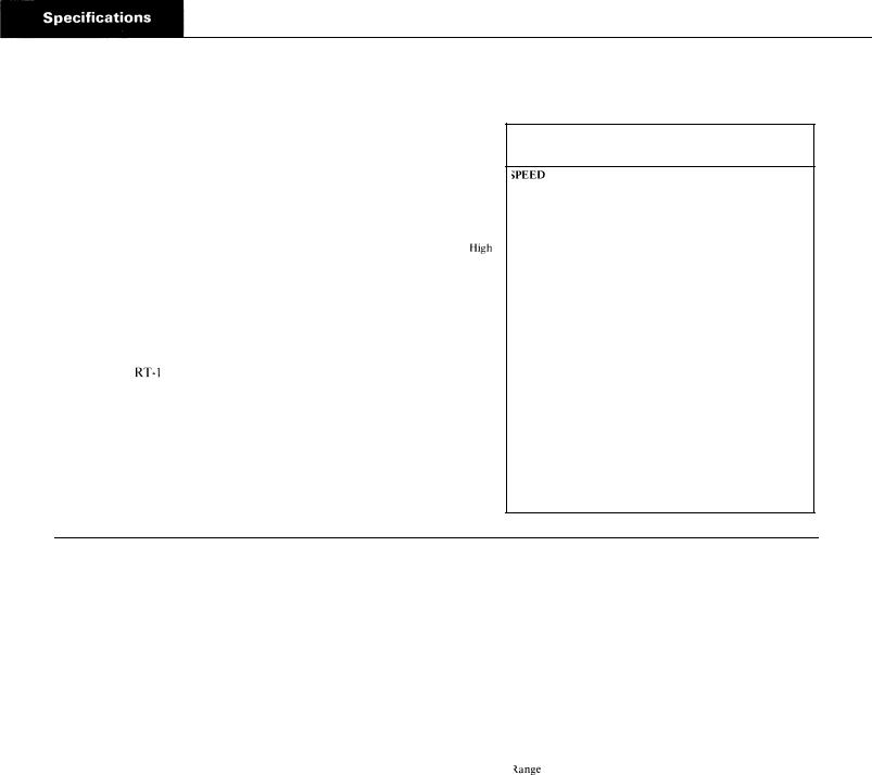
Specifications - RT-1 110 Series
Speeds 10 progressive forward speeds, 2 reverse
Nominal Torque Capacity 1100 lb.-ft.
Input Drive Shaft 2“ diameter |
|
Power Take-Off |
|
Openings |
|
Right Side: SAE standard 6 bolt regular duty type, short length. |
|
Bottom: SAE standard 8-bolt heavy-duty type. |
Range |
PTO Gear Relative Speed to Input R.P. M. |
|
Right Side: 45-tooth 6/8 pitch gear turning at .700 engine |
|
speed on RT-1 110 and RTF-1 110 models; .888 engine |
|
speed on RTO-1 110 and RTOF-1 110 models. |
|
Bottom: 47-tooth 6/8 pitch gear turning at .700 engine |
|
speed on 110 and RTF-1 110 models, .888 engine |
Low |
speed on RTO-1 110 and RTOF-1 110 models. |
Range |
|
|
Weight |
|
SAE No. 1 aluminum clutch housing with standard controls, |
|
less clutch release parts – 620 lbs. |
|
Oil Capacity |
|
Approximately 25 pints, depending on inclination of engine |
|
and transmission. Fill to level of case filler opening. |
|
|
|
|
GEAR RATIOS |
|
|
||
RT-111O and RTF-111O |
|
RTO-1 110 and RTOF-1 110 |
|||||
|
RATIO |
% STEP |
|
SPEED RATIO % STEP |
|||
|
|
||||||
10th |
1.00 |
|
27 |
|
10th |
.79 |
27 |
9th |
1.27 |
‘ |
|
9th |
1.00 |
||
30 |
|
30 |
|||||
8th |
1.65 |
|
|
8th |
1.30 |
||
|
28 |
|
28 |
||||
7th |
2.11 |
|
|
7th |
1.66 |
||
|
30 |
|
30 |
||||
6th |
2.74 |
|
|
6th |
2.16 |
||
|
|
|
|
||||
Range Shift |
|
30 |
|
Range Shift |
29 |
||
5th |
3.55 |
|
27 |
|
5th |
2.79 |
27 |
4th |
4.50 |
|
|
4th |
3.55 |
||
|
30 |
|
30 |
||||
3rd |
5.83 |
|
|
3rd |
4.59 |
||
|
28 |
|
28 |
||||
2nd |
7.49 |
|
|
2nd |
5.90 |
||
|
30 |
|
30 |
||||
1 St |
9.71 |
|
|
1 St |
7.65 |
||
|
|
|
|
||||
High |
|
|
|
|
High |
|
|
Reverse 2.74 |
|
|
|
Reverse 2.16 |
|
||
Low |
|
|
|
|
Low |
|
|
Reverse 9.71 |
|
|
|
Reverse 7.65 |
|
||
|
|
|
|
|
|
|
|
I
I
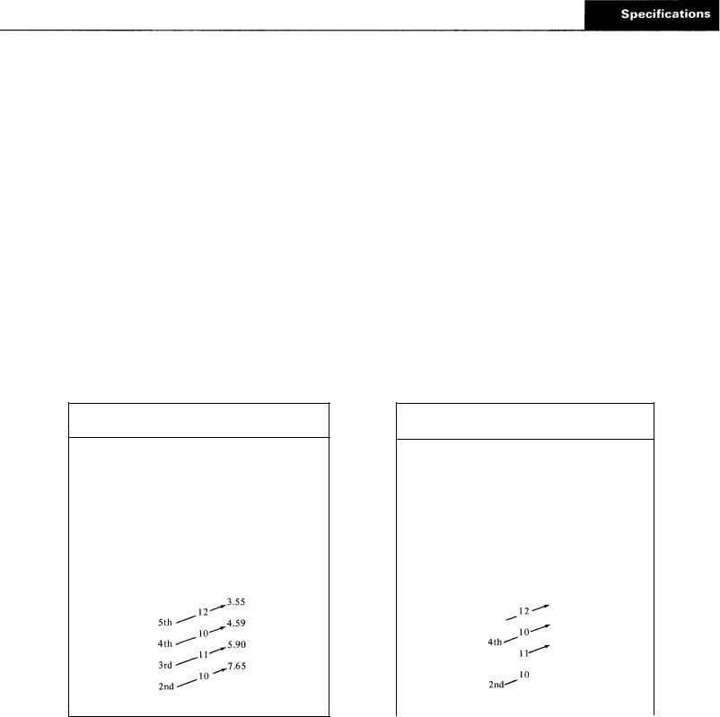
Specifications - RT-I 2510 Series
Speeds 10 progressive forward speeds, 2 reverse.
Nominal Torque Capacity 1250 lb.-ft.
Power Take-Off
Openings
Right Side: SAE standard 6-bolt regular duty type, short length.
Bottom: SAE standard 8-bolt heavy-duty type.
PTO Gear Relative Speed to Input R.P.M.
Right Side: 45-tooth 6/8 pitch gear turning at .700 engine speed on RT-1 2510 and RTF-12510 models, .888 engine speed on RTO-1 2510 and RTOF-1251O models.
Bottom: 47-tooth 6/8 pitch gear turning at .700 engine speed on RT-1251O and RTF-1 2510 models, .888 engine speed on RTO-1 2510 and RTOF-12510 models.
Weight
SAE No. 1 clutch housing with standard controls, less clutch release parts – 698 lbs.
Clutch Housing Size
SAE No. 1 deep only, 6-5/8”, for push or pull type clutches.
Oil Capacity
Approximately 25 pints, depending on inclination of engine and transmission. Fill to level of case filler opening.
|
|
|
|
GEAR RATIOS |
|
|
||
|
|
RT-1251O and RTF-1251O |
|
RTO-125 10 and RTOF-12510 |
|
|||
|
|
;PEED RATIO % STEP |
|
SPEED RATIO % STEP |
|
|||
|
|
10th |
1.00 |
|
|
10th |
.79 |
|
|
|
|
|
27 |
|
|
27 |
|
|
|
9th |
1.27 |
|
|
9th |
1.00 |
|
High |
|
|
29 |
|
|
30 |
|
|
8th |
1.65 |
|
|
8th |
1.30 |
|
||
Range |
|
|
|
|||||
|
|
28 |
|
|
28 |
|
||
|
|
|
|
|
|
|
||
|
|
7th |
2.11 |
30 |
|
7th |
1.66 |
|
|
|
|
|
|
|
30 |
|
|
|
|
6th |
2.74 |
|
|
6th |
2.16 |
|
|
|
Shift |
29 |
|
Range Shift |
29 |
|
|
|
|
5th |
3.55 |
|
|
5th |
2.79 |
|
|
|
|
|
27 |
|
|
27 |
|
|
|
4th |
4.50 |
|
|
4th |
3.55 |
|
|
|
|
|
29 |
|
|
30 |
|
Low |
3rd |
5.83 |
28 |
|
3rd |
4.59 |
|
|
Range |
|
|
|
|
28 |
|
||
2nd |
7.49 |
|
|
2nd |
5.90 |
|
||
|
|
|
|
|
||||
|
|
|
|
30 |
|
|
30 |
|
|
|
1 St |
9.71 |
|
|
1 St |
7.65 |
|
|
|
High |
|
|
|
High |
2.16 |
|
|
|
Reverse |
2.74 |
|
|
Reverse |
|
|
|
|
Low |
|
|
|
Low |
7.65 |
|
|
|
|
|
|
|
|||
|
|
Reverse |
9.71 |
|
|
Reverse |
|
|
|
|
|
|
|
|
|
|
|
Specifications - RT-1 2515 Series
Speeds
15 forward speeds, 3 reverse. Five deep reduction ratios, plus evenly spaced ratios for a selective 11 or 12 progressive ratios.
RTO-12515 and RTOF-12515
Right Side: 45-tooth 6/8 pitch gear turning .888 engine speed. Bottom: 47-tooth 6/8 pitch gear turning .888 engine speed.
Clutch Housing Size
Nominal Torque Capacity |
SAE No. 1 deep only, 6-5/8”, for push or pull type clutches. |
1250 lb.-ft. |
Weight |
|
Power Take-Off
Openings
Right Side: SAE standard 6-bolt regular duty type, short length.
Bottom: SAE standard 8-bolt heavy-duty type.
PTO Gear Relative Speed to Input R.P. M.
RT-12515 and RTF-12515
Right Side: 45-tooth 6/8 pitch gear turning .700 engine speed. Bottom: 47-tooth 6/8 pitch gear turning .700 engine speed.
SAE No. 1 clutch housing, with standard controls, less clutch release parts – 770 lbs.
Oil Capacity
Approximately 28 pints, depending on inclination of engine and transmission. Fill to level of case filler opening.
Deep
Red.
Range
GEAR RATIOS
RTO-12515 and RTOF-125 15
RANGE
RATIO % STEP SPEED % STEP RATIO % STEP SPEED
|
.79 |
10th |
|
1.00 |
27 |
|
9th |
|
|
1.30 |
30 |
|
8th |
|
|
1.66 |
28 |
|
7th |
|
|
2.16 |
30 |
|
6th |
|
|
29 |
|
|
2.79 |
5th |
|
|
27 |
|
|
4th |
3.99 |
|
30 |
27 |
3rd |
|
|
28 |
|
5.07 |
29 |
2nd |
|
30 |
|
6.56 |
28 |
1 St |
8.43 |
|
|
29 |
|
|
|
|
|
10.93 |
1 St |
|
High Reverse . . . . . . . . . . . . . . . . . . . . 2.16
Low Reverse . . . . . . . . . . . . . . . . . . . . . 7.65
Deep Reduction Reverse . . . . . . . . . ...10.93
High
Range
Low
Range
Deep
Red.
Range
GEAR RATIOS
RT-12515 and RTF-12515
RANGE
RATIO % STEP SPEED % STEP  % STEP SPEED
|
|
1.00 |
10th |
|
|
|
27 |
|
|
1.27 |
9th |
|
|
|
29 |
|
|
1.65 |
8th |
|
|
|
28 |
|
|
2.11 |
7th |
|
|
|
30 |
|
|
2.74 |
6th |
|
|
29 |
5th |
|
|
3.55 |
|
|
|
|
27 |
|
|
4.50 |
4th |
5.07 |
5th |
|
29 |
5.83 |
3rd |
||
6.43 |
27 |
|
28 |
30 |
7.49 |
2nd |
|
|
/ 9.71 |
30 |
|
8.34 |
3 r d ’ |
1 St |
|
10.70 |
28 |
|
|
29 |
|
|
|
|
|
|
|
13.87 |
1 St |
|
|
|
|
|
|
High Reverse . . . . . . . . . . . . . . . . . . . . . . . . 2.74
Low Reverse . . . . . . . . . . . . . . . . . . . . . . . . 9.71
Deep Reduction Reverse . . . . . . . . . . . . ...13.87
High
Range
Low
Range

LUBRICATION
|
Proper |
|
|
|
|
|
|
|
|
Recommended |
Lubricants |
|
||||||
|
|
|
|
|
|
|
|
|
|
|
|
|
||||||
|
Lubrication . . . |
|
|
|
|
|
|
|
|
|
|
Fahrenheit |
|
|||||
|
|
|
|
|
|
|
|
|
|
Grade |
(Celsius) |
|
||||||
|
|
|
|
|
|
|
|
|
|
|
|
|
|
|
Ambient |
|
||
|
the Key to long |
|
|
|
|
Type |
|
|
(SAE) |
Temperature |
|
|||||||
|
|
|
|
|
|
|
|
|
|
|
|
|
||||||
|
|
|
|
|
Eaton® Roadranger® |
|
|
|
|
|||||||||
|
transmission life |
|
|
|
CD50 Transmission |
|
50 |
|
All |
|
||||||||
|
|
|
|
Heavy Duty Engine 011 |
|
|
|
|||||||||||
|
|
|
|
|
|
|
|
|
|
|
Fluid |
|
|
|
|
|
||
|
Proper lubrication procedures are the key to a |
|
MI L-L-2104B C or D or |
|
50 |
Above 10oF(-12oC.) |
|
|||||||||||
|
|
API-SF or API-CD |
|
|
40 |
Above 10oF(-12oC.) |
|
|||||||||||
|
good all-around maintenance program. If the |
|
(Previous API designations |
|
30 |
Below 10oF(-12oC.) |
|
|||||||||||
|
oil is not doing its job, or if the oil level is |
|
acceptable) |
|
|
|
|
|
|
|||||||||
|
ignored, all the maintenance procedures in the |
|
|
|
|
|
||||||||||||
|
|
Mineral Gear 011 with rust |
90 |
Above 10oF(-12oC.) |
|
|||||||||||||
|
world are not going to keep the transmission |
|
and oxidation Inhibitor |
|
80W |
Below 10oF(-12oC.) |
|
|||||||||||
|
running or assure long transmission life. |
|
|
|
API-GL-1 |
|
|
|
|
|
|
|
||||||
|
Eaton® Fuller® |
Transmissions are |
designed |
|
|
|
|
|
|
|
|
|
||||||
|
|
The use of mild EP gear oil or multi-pur- |
||||||||||||||||
|
so that the internal parts operate in a bath of |
|
||||||||||||||||
|
oil circulated by the motion of gears and shafts. |
|
pose gear oil is not recommended, but if |
|||||||||||||||
|
Thus, ail parts will be amply lubricated if |
|
these gear oils are used, be sure to adhere to |
|||||||||||||||
|
these procedures are closely followed: |
|
|
|
the following limitations: |
|
|
|
||||||||||
|
1. Maintain oil level. Inspect regularly. |
|
|
|
Do not use mild EP gear oil or multi-pur- |
|||||||||||||
|
2. Change oil regularly. |
|
|
|
|
|
|
pose gear oil when operating temperatures are |
||||||||||
|
3. Use the correct grade and type of oil. |
|
above 230°F (110oC). Many of these gear oils, |
|||||||||||||||
|
4. Buy from a reputable dealer. |
|
|
|
|
|
particularly 85W140, break down above 230°F |
|||||||||||
|
Lubrication |
Change |
and Inspection |
|
and coat seals, bearings and gears with de- |
|||||||||||||
|
|
posits that may cause premature failures. If |
||||||||||||||||
|
|
|
|
|
|
|
|
|
|
|
||||||||
|
Eaton® |
Roadranger ® CD50 |
Transmission |
Fluid |
|
|
these deposits are observed (especially a coat- |
|||||||||||
|
|
|
|
|
|
|
|
|
|
|
ing on seal areas causing oil leakage), change |
|||||||
|
HIGHWAY USE—Heavy Duty and Mid-Range |
|
|
|||||||||||||||
|
|
|
to Eaton Roadranger CD50 transmission fluid, |
|||||||||||||||
|
|
|
|
|
|
|
|
|
|
|
||||||||
|
First 3,000 to 5,000 miles |
|
|
Factory fill |
|
|
||||||||||||
|
|
|
|
|
heavy duty engine |
oil or |
mineral |
gear oil to |
||||||||||
|
(4827 to 8045 Km) |
|
|
|
Inltlal |
drain |
|
|
assure maximum component life and to main- |
|||||||||
|
Every 10,000 miles |
|
Check fluid |
level |
|
|
||||||||||||
|
|
|
|
tain your |
warranty |
with Eaton. (Also see |
||||||||||||
|
(16090 Km) |
|
|
Check for leaks |
|
|
“Operating |
Temperatures”.) |
|
|
||||||||
|
Heavy |
Duty Highway |
Change Interval |
|
|
|
|
|
||||||||||
|
|
|
|
Additives |
and |
friction modifiers |
are not recom- |
|||||||||||
|
|
|
|
|
|
|
|
|
|
|
||||||||
|
Every 250,000 miles |
|
Change |
transmission |
|
|
||||||||||||
|
|
|
|
mended |
for |
use |
in Eaton Fuller |
transmissions. |
||||||||||
|
(402336 Km) |
|
|
|
|
|
fluid, |
|
|
|||||||||
|
|
|
|
|
|
|
|
|
|
|
|
|
|
|
|
|||
|
|
|
|
|
|
|
|
|
|
|
|
|
||||||
|
Mid-Range Highway Change Interval |
|
|
|
|
|
|
|
|
|
|
|
||||||
|
|
|
|
|
|
|
|
|
|
|
|
|
|
|||||
|
Every 100,000 miles (160,000 Km) |
Change |
transmission |
|
|
|
|
|
|
|
|
|
|
|||||
|
or every 3 years whichever occurs |
first |
|
|
fluid. |
|
|
|
|
|
|
|
|
|
|
|||
|
|
|
|
|
|
|
|
|
|
|
|
|
|
|
|
|
||
|
|
|
OFF-HIGHWAY USE |
|
|
|
|
|
|
|
|
|
|
|
|
|
||
|
First 30 |
hours |
|
|
Factory |
fill |
Initial |
drain, |
|
|
Proper |
Oil Level |
|
|
|
|||
|
|
|
|
|
|
|
|
|
||||||||||
|
Every 40 hours |
|
Inspect fluid level Check for leaks |
|
|
|
|
|
||||||||||
|
|
|
|
|
|
|
|
Make sure oil is level with filler opening. Be- |
||||||||||
I |
Every 500 hours |
|
Change transmission |
fluid |
where |
|
|
|||||||||||
|
|
|
severe dirt |
conditions |
exist. |
|
|
cause you can reach oil |
with your finger does |
|||||||||
I |
|
|
|
|
|
not mean oil is at proper level. One inch of oil |
||||||||||||
Every 1,000 hours |
|
Change transmission fluid |
|
|
||||||||||||||
|
|
|
|
(Normal off-highway use), |
|
|
level is about one |
gallon |
of oil. |
|
|
|||||||
|
|
|
|
|
|
|
|
|
|
|
|
|
|
|
||||
|
|
|
|
|
|
Draining |
Oil |
|
|
|
|
|
||||||
|
|
Heavy Duty Engine Lubricant or |
|
|
|
|
|
|
|
|
||||||||
|
|
|
Mineral Gear Lubricant |
|
|
|
|
|
Drain transmission while oil is warm. To drain |
|||||||||
|
|
|
|
|
|
|
|
|
|
|
||||||||
I |
|
|
|
HIGHWAY USE |
|
|
|
|
|
|||||||||
|
|
|
|
|
|
|
|
oil remove the drain plug at bottom of case. |
||||||||||
I |
First 3,000 to 5,000 miles |
|
|
Factory fill |
|
|
Clean the drain plug before re-installing. |
|||||||||||
(4827 to 8045 Km) |
|
|
|
Initial |
drain. |
|
|
Refilling |
|
|
|
|
|
|
||||
Every 10,000 miles |
|
Inspect |
Iubricant |
level, |
|
|
|
|
|
|
|
|
||||||
I |
|
|
|
Clean case around filler plug and remove plug |
||||||||||||||
(16090 Km) |
|
|
Check for leaks, |
|
|
|||||||||||||
I |
|
|
|
|
|
|
from side of case. Fill transmission to the |
|||||||||||
Every 50,000 miles |
|
Change |
transmission |
|
|
|||||||||||||
(80450 Km) |
|
|
|
|
lubricant, |
|
|
level of the filler opening. If transmission has |
||||||||||
I |
|
|
OFF-HIGHWAY USE |
|
|
|
|
|
two filler openings, fill to level of both open- |
|||||||||
|
|
|
|
|
|
|
|
|
|
|
ings. |
|
|
|
|
|
|
|
|
First 30 |
hours |
Change transmission lubricant on new |
units |
|
|
|
|
|
|
|
|
|
|||||
|
|
|
The exact amount of oil will depend on the |
|||||||||||||||
|
|
|
|
|
|
|
|
|
|
|
||||||||
|
|
|
|
|
|
|
|
|
|
|
||||||||
|
Every 40 |
hours |
|
Inspect Iubricant level Check for leaks |
|
|
transmission inclination and model. Do not |
|||||||||||
|
Every 500 hours |
|
Change transmission |
Iubricant |
where |
|
|
over fill—this |
will cause oil to be |
forced out |
||||||||
|
|
|
|
severe dirt |
conditions |
exist. |
|
|
of the transmission. |
|
|
|
||||||
|
Every 1,000 hours |
Change transmission Iubricant |
|
|
When adding oil, types and brands of oil |
|||||||||||||
|
|
|
|
|
(Normal off-highway use), |
|
|
should not be mixed because of possible in- |
||||||||||
|
Change the oil filter when fluid or lubricant is changed. |
4 |
compatibility. |
|
|
|
|
|
||||||||||
,. .. . .
LUBRICATION
Operating Temperatures
—With Eaton® Roadranger ®
CD50 Transmission Fluid
Heavy Duty Engine Oil
and Mineral Oil
The transmission should not be operated consistently at temperatures above 250oF (120oC). However, intermittent operating temperatures to 300oF (149oC) will not harm the transmission. Operating temperatures above 250oF increase the lubricant’s rate of oxidation and shorten its effective life. When the average operating temperature is above 250oF, the transmission may require more frequent oil changes or external cooling.
The following conditions in any combination can cause operating temperatures of over 250oF: (1) operating consistently at slow speeds, (2) high ambient temperatures, (3) restricted air flow around transmission, (4) exhaust system too close to transmission, (5) high horsepower, overdrive operation.
External oil coolers are available to reduce operating temperatures when the above conditions are encountered.
Transmission Oil Coolers are:
Recommended
—With engines of 350 H.P. and above with overdrive transmissions
Required
—With engines 399 H.P. and above with overdrive transmissions and GCW’S over 90,000 lbs.
—With engines 399 H.P. and above and 1400 Lbs.-Ft. or greater torque
—With engines 450 H.P. and above
—With EP or Multipurpose Gear Oil
Mild EP gear oil and multipurpose gear oil are not recommended when lubricant operating temperatures are above 230°F (110). In addition, transmission oil coolers are not recommended with these gear oils since the oil cooler materials may be attacked by these gear oils. The lower temperature limit and oil cooler restriction with these gear oils generally limit their success to milder applications.
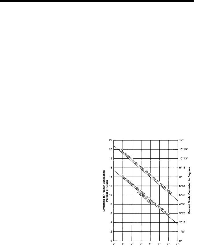
Proper Lubrication Levels as Related to Transmission Installation Angles
If the transmission operating angle is more than 12 degrees, improper lubrication can occur. The operating angle is the transmission mounting angle in the chassis plus the percent of upgrade (expressed in degrees).
The chart below illustrates the safe percent of upgrade on which the transmission can be used with various chassis mounting angles.
For example: if you have a 4 degree transmission mounting angle, then 8 degrees (or 14 percent of grade) is equal to the limit of 12 degrees. If you have a O degree mounting angle, the transmission can be operated on a 12 degree (21 percent) grade.
Anytime the transmission operating angle of 12 degrees is exceeded for an extended
period of time the transmission should be equipped with an oil pump or cooler kit to insure proper lubrication.
Note on the chart the effect low oil levels can have on safe operating angles. Allowing the oil level to fall 1/2” below the filler plug hole reduces the degree of grade by approximately 3 degrees (5.5 percent).
Proper Lubrication Levels are Essential!
Transmission Mounting Angle
Dotted line showing “2 Quarts Low” is for reference only. Not recommended.
5
Operation
In the following instructions, it is assumed that the driver is familiar with motor trucks and tractors, and that he can coordinate the necessary movements of the shift lever and clutch pedal to make progressive and selective gear engagements in either direction, up or down.
RT-I 110 and RT-12510 Operation
The RT-1 110 and RT-12510 have ten selective ratios, evenly and progressively spaced. Do not shift these transmissions as you would a conventional model with an auxiliary or two-speed axle, because there is no split-shifting.
All shifts are made with one lever. The range control button is used one time only during an upshift sequence, and one time only during a downshift sequence.
Since the transmissions consist of a five-speed front section and a two-speed range section, the ten forward speeds are obtained by using a five-speed shifting pattern twice – the first time with the transmission in low range, and the second time with the transmission in high range.
Ten speeds obtained with one gear shift lever and range control button.
Shift pattern for the RT-1110 and R T-1251 O model transmissions.
Shift pattern for the R TO-1I10andRTO-12510 model transmissions.
10
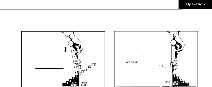
Upshifting
To get to high range pull button UP
while in 5th speed,
then move lever
to 6th speed.
Upshifting
1.Move the gearshift lever to the neutral position.
2.Start the engine.
3.Wait for air system to reach normal line pressure.
4.Now look at the Range Control Button. If it is up push it to the down position. (With the downward movement of the button, the transmission will shift into low range.) If the button was down when the truck was last used, the transmission is already in low range.
5.Now start the vehicle and shift progressively through 1st, 2nd, 3rd and 4th to 5th.
6.When in 5th and ready for the next upward shift, PULL
the Range Control Button UP and move the lever to 6th
speed. As the lever passes through the neutral position,
the transmission will automatically shift from low range to high range.
7.With the transmission in high range, you may now shift progressively through 7th, 8th and 9th to 10th.
Driving tip: always start vehicle moving in first speed gear.
Downshifting
To get to low range push button DOWN
|
|
|
|
|
|
|
|
10 |
|
6th speed, |
||||
9 |
||||
then move |
8 |
|||
7 6 |
||||
lever to 5th speed. |
||||
|
||||
speed. |
|
|||
|
|
|
RANGE |
|
|
|
|
|
|
Downshifting
1.When shifting down, move the lever from 10th through each successive lower speed to 6th.
2.When in 6th, and ready for the next downward shift,
PUSH the Range Control Button DOWN and move the lever to 5th speed. As the lever passes through the neu-
the transmission will automatically shift from high range to low range.
3.With the transmission in low range, shift downward through each of the four remaining steps.
11
General Instructions
The shift through neutral is important only on the first shift made after the control button is moved. Subsequent shifts through neutral will not activate the automatic range shift until the control button is moved once more.
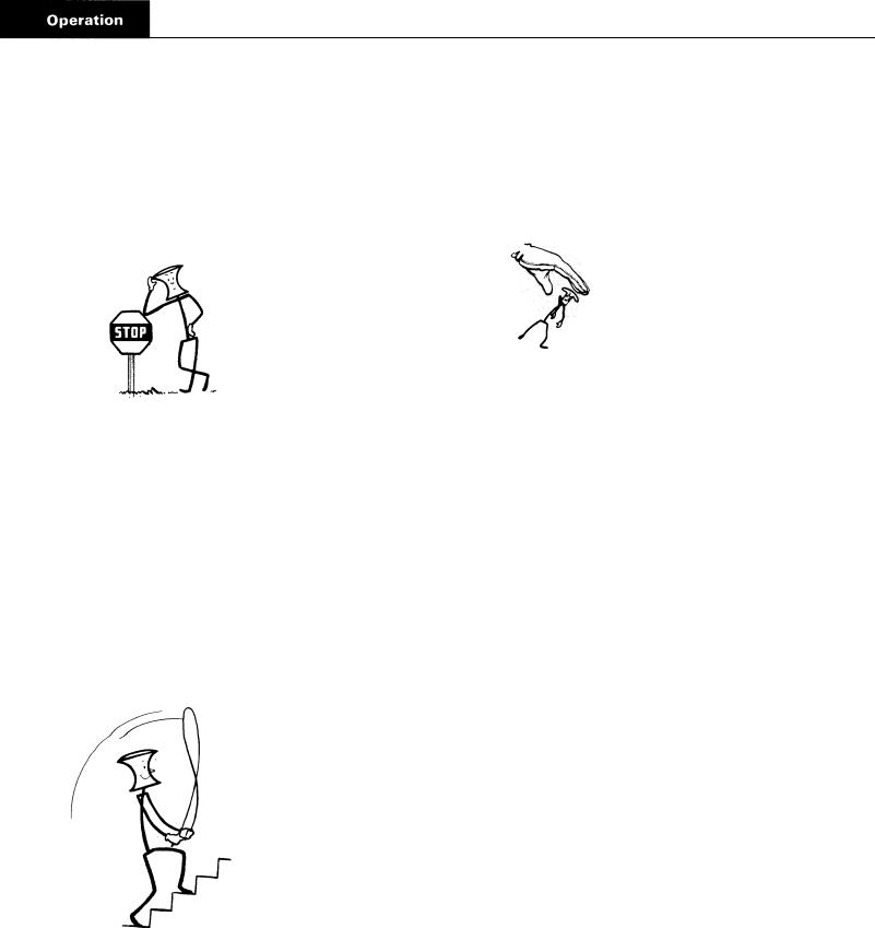
When necessary to slow or
,. stop the vehicle, shift
.
down through the individual short steps, allowing the compression of the engine to slow the vehicle. The life of chassis and trailer brakes can thus be prolonged.
When slowing the vehicle, it is also permissible to coast in high range with the clutch disengaged. The shift to low range, however, should not be made until it is necessary to accelerate the vehicle once more.
Shifts will be fast and short as the gear shift lever stroke is 2% inches between positions. Conical engagement teeth are standard on these transmissions, thus helping to eliminate gear clashing. Gear ratios average 26 per cent between ratio steps.
Skip Shifting
After becoming proficient in shifting this transmission, the operator may wish to skip some of the gear ratios to offset a particular Operating condition. Skip shifting can be done when upshifting providing the range control button is pulled up to the high range position before making any shift which
passes fifth speed.
Skip shifting is also possible during downshifting providing the range control button is pushed down to the low range
position before making any shift which passes sixth speed.
Precautions
To protect the transmission from abuse, the following precautions should be observed when shifting the vehicle:
1. Do not attempt to shift from high range to low range at high vehicle speeds. This downward range shift should be made only at a road speed equal to that provided by fifth or a lower gear at governed engine speed.
2.Do not attempt to make any range shifts either up or down when the vehicle is moving in reverse. Stay in the range originally selected.
A mylar shift diagram is furnished with each transmission  should be installed on the vehicle dashboard. If it has been misplaced, new m
  shift diagrams can be purchased from the Service
  t, Transmission Division, Eaton Corporation, Kalamazoo, Michigan.
12
RT-12515 and RTO-12515 Operation
The RT-125 15 transmission, like the RT-125 10, has a fivespeed front section and a two-speed auxiliary or range section which enables the driver to select 10 forward speeds, evenly and progressively spaced. However, the RT-125 15 models have an additional five speeds obtained through a deep reduction gear (hole-gear).
The 10 ratios in high and low range are obtained with one lever and a range control button. The five speeds in deep reduction are obtained with the same gearshift lever and a Deep Reduction Valve which controls the “IN” or “OUT” position of the reduction gear.
The five ratios in deep reduction are evenly and progressively spaced. These five ratios, however, overlap the low range ratios and are not progressively spaced in relation to the low range ratios.
The deep reduction gear should be used only when
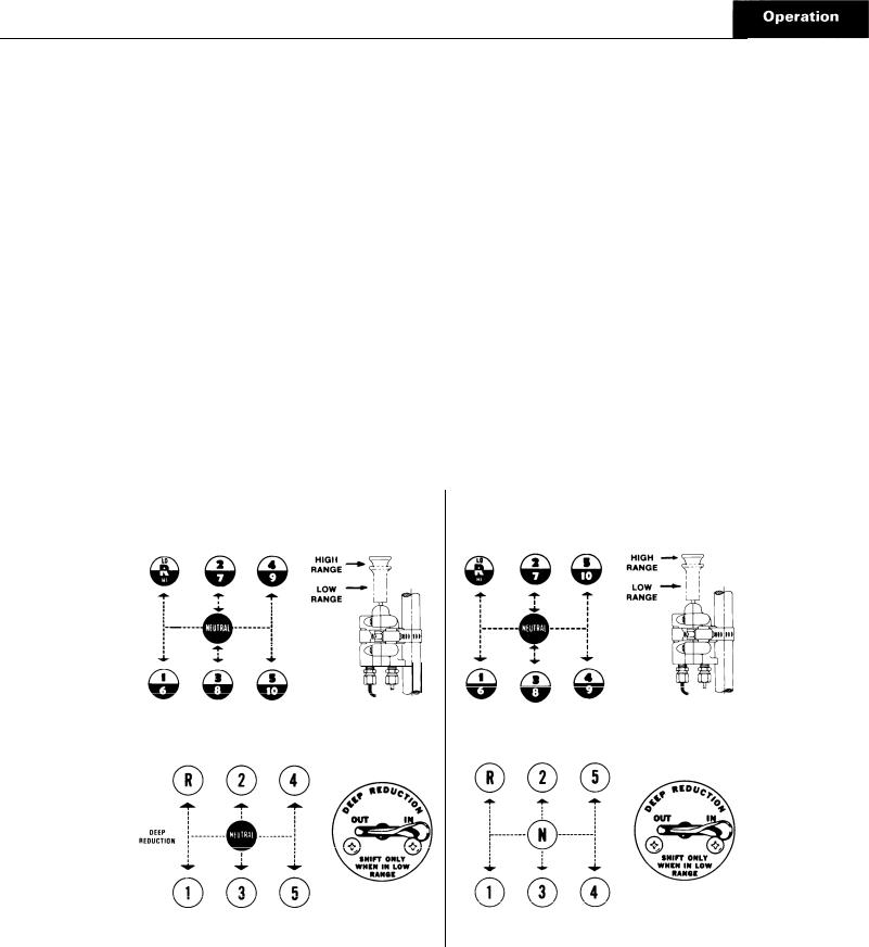
SHIFTING DIAGRAM OF THE RT-12515
Fifteen speeds obtained with one gear  lever, a Range Control Button and a Deep Reduction Valve. (Ratios shown with each gear shift lever position.)
One through 10 speeds . . . with Range Control Button
. . . and Deep Reduction gear disengaged.
Five additional ratios . . . with Deep Reduction gear engaged.
operating under adverse conditions and only when the transmission is in LOW RANGE with the control valve button down. Never move the Deep Reduction Valve to “IN” when in high range. When the valve is moved to “IN” the reduction ratios will be engaged regardless of the position of the Range Control Button.
The RTO-12515 is operated in the same manner as the RT-125 15 except for the reversal of the 4th and 5th gearshift lever positions.
Upshift Through Low and High Range
Shift upward through the 10 speeds of low and high range in the same manner as upshifting the RT-12510 or RTO12510 model transmissions. MAKE SURE THE DEEP REDUCTION VALVE IS IN THE “OUT” POSITION AT ALL TIMES during the low and high range shifts.
SHIFTING DIAGRAM OF THE RTO-12515
Fifteen speeds obtained with one gear shift lever, a Range Control Button and a Deep Reduction Valve. (Ratios shown with each gear shift lever position.)
One through 10 speeds . . . with Range Control Button
. . . and Deep Reduction gear disengaged.
Five additional ratios . . . with Deep Reduction gear engaged.
13
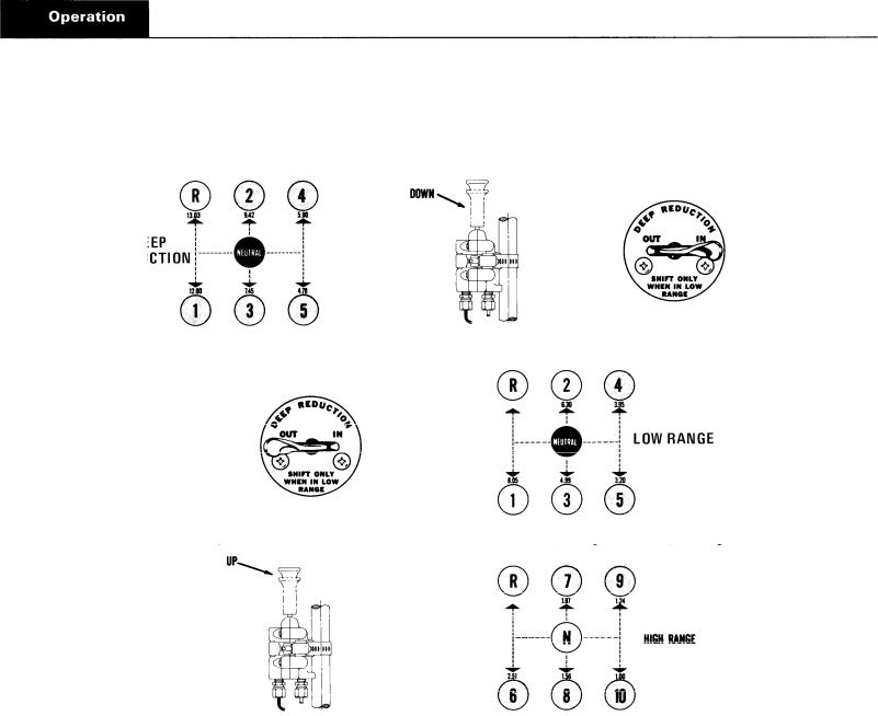
SUGGESTED SHIFT PATTERN FOR THE RT-12515 THROUGH REDUCTION AND LOW AND HIGH RANGE
(Ratios shown next to each gear shift lever position)
Shift 1 through 5 with range control button down and deep reduction valve to “IN”
Move deep reduction valve to “OUT” while in 5th reduction . . . and shift through 4th & 5th of low range
Pull |
range control button up while in 5th of low range . . . and shift 6th through 10th |
||
Upshift Through |
Deep Reduction, |
|
|
Low and High Range |
|
|
|
There are several patterns of upshifting depending upon |
2. |
Move the Deep Reduction Valve to the “IN” position to |
|
conditions of road and load. Check gear ratios to determine |
|
engage the deep reduction gear. |
|
the best ratio split for your particular condition. The fol- |
|
|
|
lowing instructions are recommended for average condi- |
3. |
Start the vehicle and shift progressively from 1st through |
|
tions: |
|
|
5th of the shift pattern. |
1. With the gearshift lever in neutral, the engine started and 4. When in 5th speed position and ready for the next upair system pressure normal, PUSH THE RANGE CON-
TROL BUTTON TO THE DOWN POSITION.
14

out of the reduction ratios to low range ratios. Torque will keep the reduction gear engaged until the shift out of fifth position is made. Remember, although the shift lever is moved from 5th to 4th, this is an upshift and accelerator must be moved accordingly. There will be no automatic range shift as the transmission already is in low range.
5.Shift through the 4th and 5th speed positions of low range.
6.When ready for the next upshift, pull the Range Control Button up while in the 5th speed position of low range and shift the lever to the first speed position of the shift pattern. As the lever passes through neutral, the transmission will automatically shift from low to high range.
7.Shift progressively upward from 6th through 10th in high range.
NOTE: The above is for the RT-12515.  RTO12515 shift from reduction to low range would differ, according to the ratios desired.
Important Procedures
1.When making the shift from a reduction ratio to a low range ratio, move the Deep Reduction Valve from “IN” to “OUT” IMMEDIATELY BEFORE making the shift. This is not a pre-select valve and only torque will hold the reduction gear after the lever is moved to “OUT”; the shift cylinder will make the shift by air as soon as torque is released.
2.Never move the Deep Reduction Valve lever with the transmission in high range (range control button up) as the reduction gear bypasses both the low and high range sections, regardless of the position of the range control button.
3.When downshifting it should not be necessary to shift into deep reduction ratios. The reduction in low range should be sufficient in most operating conditions.
All instructions pertaining to the Range Control Button, skip shifting and general precautions of the ten-speed shift pattern of the RT-1 110 and RT-1251O apply as well to the RT-12515.
15

Air Systems
Range Shift Air System – All Models
This system consists of an air filter, regulator, air valve, control valve, shift cylinder, fittings and connecting lines. See Illustration A.
Constant regulated air is supplied to the bottom port of the air valve and to the “IN” port of the control valve. With the control button down, air passes through the control valve and to the end port of the air valve. This permits air from the constant supply to flow through the low range port in bottom, side cap of air valve and to the shift cylinder air port. Air on this port moves the shift piston and bar to the rear to engage the low range gear.
With the control button up the control valve is closed and air is removed from end port of air valve. This permits air
from the constant supply to flow through the high range port in rear, side cap of air valve and to the shift cylinder cover air port. Air on this port moves the shift piston and bar forward to engage the high range gear.
When the control button is moved from one position to another, air from the previously charged line exhausts through the breather in air valve.
On some transmissions the air valve may be installed in a 180° position from that shown in Illustration A. The porting on these models, however, remains the same. The bottom port in the side cap is always the low range port.
16
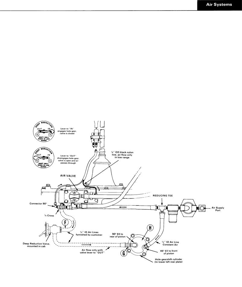
Hole-Gear Air System – RT-12515 Series
This system uses the air filter and regulator of the range shift air system, plus a Deep Reduction Valve, mounted in the vehicle’s cab, and a holegearshift cylinder. See Illustration B.
Constant regulated air is supplied to the end port of the deep reduction valve and to the air port in the lower, right side of the hole -gearshift cylinder cover.
The deep reduction valve lever has two positions, “IN” and “OUT”. With the lever moved to the “IN” position the valve is off. Thus, constant air channeled through the shift
cylinder and cover to the front of the shift piston moves the piston and shift bar to the rear to engage the hole-gear. As the hole-gear is engaged the range mainshaft is disengaged from the output shaft, removing the low and high range sections from the power flow.
With the deep reduction valve lever moved to the “OUT” position air flows out the side port of the valve and to the air port near the center of the hole -gearshift cylinder cover. This air, pushing against a larger piston area than the constant air supply, moves the shift piston and bar forward to disengage the hole-gear. As the hole-gear is disengaged, the range mainshaft is engaged to the output shaft, permitting use of the low and high range sections.
B. Hook-up diagram and troubleshooting checkpoints for the hole-gear air system.
17

Air Valve Operation
With the range control button up the control valve shuts off the air supply to the end cap. Thus, the constant air  ing at the constant supply port forces the piston to the rear. The constant air also flows through a channel in the center of the piston and to an external port which is aligned with the high range port of the air valve.
With the control button down the control valve opens and supplies air to the end cap. Since the piston area is larger on this end of the piston, it is forced in the opposite direction. The external air port in the piston is now aligned with the low range port of the air valve.
C. Exploded view of  value. The alignment sleeve
  not part of
  assembly, but must be
 housing for proper
  operation.
The four O-rings are indicated by circled numbers. If any of these are defective, there will be a constant air leak out of the exhaust on the air valve. In normal operation, exhaust will occur only for an instant as the range shift is made. The following chart is to be used as a guide to determine defective O-rings.
|
|
Defective |
RESULT |
|
|
|
O-Rings |
||
|
|
|
|
|
|
|
1 |
Constant leak through exhaust in low range only. |
|
|
|
2 o r 3 |
Constant leak through exhaust in both ranges. |
|
|
|
4 |
Constant leak through exhaust in high range; steady but low volume |
|
|
|
|
leak through exhaust in low range. |
|
|
|
|
|
|
To |
Disassemble Air Valve |
|
|
|
1. |
Turn out the two capscrews |
and remove the side cap 4. Turn end cap from valve body and withdraw piston from |
||
|
from valve body. |
bore. |
||
2. |
Remove the valve insert from piston and remove O ring 5. Remove the two O-rings from piston. |
|||
|
from the valve insert. |
6. Remove the nylon plug from piston and remove O-ring |
||
|
|
|
||
3. |
Remove the spring from piston. |
from plug. |
||
18
Air Valve Pre-Selection
An actuating pin protruding from the shifting bar housing prevents the actuating piston in the air valve from moving while the gearshift lever is in a gear position and releases the
piston when the lever is moved to or through neutral. See detailed installation of air valve for installation precaution concerning the actuating pin.
SLEEVE
D, Cross-section  actuating pin and plunger assembly.
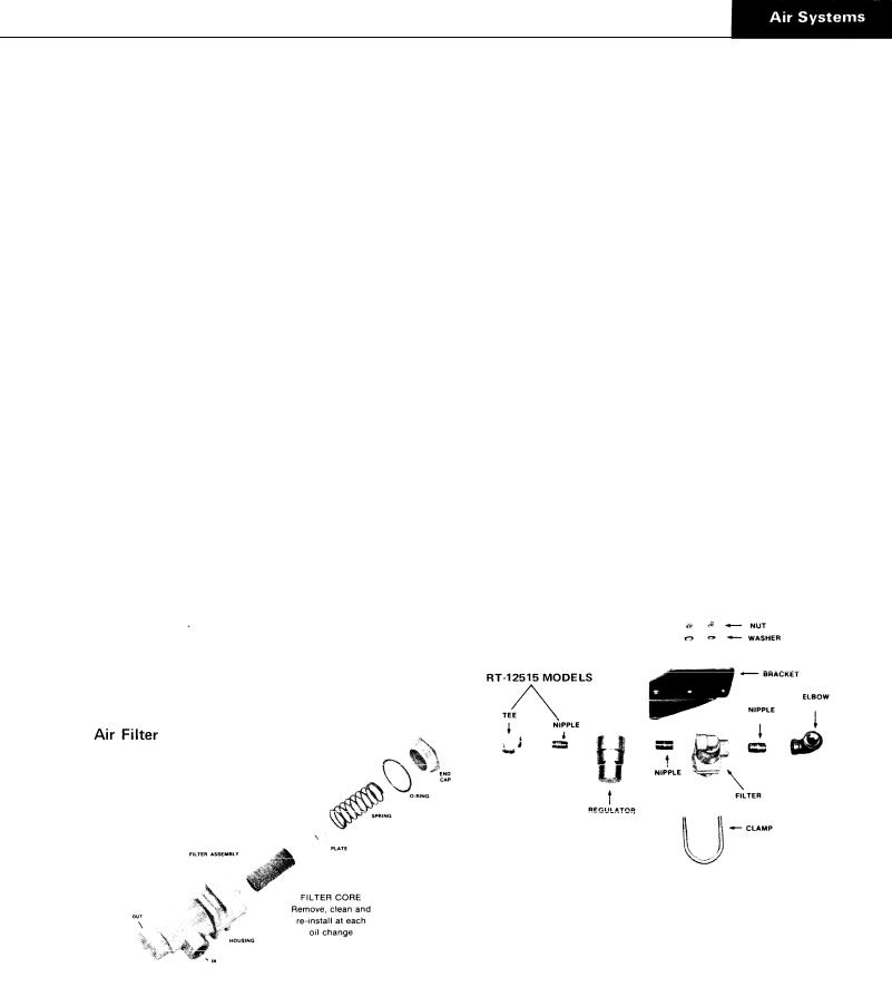
Air Regulator |
Air Filter & Regulator Assembly |
The air regulator is not serviceable. If defective replace the air regulator unit. Reading at output of air regulator should be 57.5 to 62.5 psi.
19
E. Exploded of control value. The “IN’’port constant supply. The “OUTLET” port connected by |
O. L). |
air  to
to  cap of air ualoe.
If the O-rings or parts in the control valve are defective there will be a constant air leak out the exhaust located on bottom of control valve.
A defective insert valve O-ring will result in a constant leak through exhaust in both ranges and valve will not make range shifts.
A defective housing O-ring will result in a constant, low volume leak through exhaust in low range only.
2. Remove the slide and the two position balls and springs.
3.Remove the flat metal seal from outlet side and remove the O-ring from body.
4. Remove the valve insert from front housing and remove the O-ring from valve insert.
5. Remove the wave washer installed under valve insert.
6.Remove the two felt wipers from valve housings.
7.Punch out roll pin and remove control button from slide.
If the slide is assembled backwards, there will be a constant leak through exhaust in high range. When installing slide in control valve make sure that slot in slide faces the outlet part.
To Disassemble the Control Valve
1.Remove the four screws to separate front and rear housings.
Air Valve O-Ring sizes, Ill. C
Qty. |
Location |
ID |
Width |
|
|
|
|
2 |
Valve Insert and Plug |
. 208 |
.070 |
1 |
Piston |
. 549 |
. 103 |
1 |
Piston |
. 364 |
. 070 |
|
|
|
|
|
Control |
Valve O-Ring sizes, Ill. E |
|
|
1 |
Valve Insert |
|
.301 |
. 0 7 0 |
1 |
H o u s i n g |
|
. 375 |
. 062 |
|
|
|
|
|
20

Trouble Shooting
Range Shift Air System All Models
The following checks are to be made with normal vehicle air pressure but with the engine off. Refer to Illustration A for check points.
1.Incorrect Hook-Up
With normal vehicle air pressure and gearshift lever in the neutral position, move the control button up and down, from one range to another.
a.If lines are crossed between the control valve and the air valve on transmission, there will be a steady flow of air from the top exhaust in control valve if button is held in the up position.
bIf lines are crossed between the air valve on transmission and the air or shift cylinder, the transmission gearing will not correspond with the button position. Low range, down position of button, will result in high range gear engagement in the transmission and vice versa.
2.Air Leaks
With normal vehicle air pressure and gearshift lever in the neutral position, coat all air lines and fittings with soapy water and check for leaks, moving control button to both positions.
a.If there is a steady leak out exhaust of control valve, there are defective parts or O-rings in the control valve.
b.If there is a steady leak out breather on air valve; there is a defective O-ring in the air valve; or there is a leak past O-rings on the shift cylinder piston (see Ill. F, Check Point E).
c.If transmission fails to shift into low range or is slow to make the shift and the transmission case is pressurized, see Ill. F, Check Point E.
d.Tighten all loose connections and replace defective parts or O-rings.
3.Air Regulator, Check Point A
If there is a steady leak from exhaust port, this indicates a defective air regulator and should be replaced.
Cut off the vehicle air pressure and install air gauge in line at output port of air regulator. Bring vehicle air pressure to normal. Regulated pressure should be 57.5 to 62.5 psi.
If correct pressure readings are not obtained, replace regulator.
4.Control Valve, Check Point B
With the gearshift lever in neutral, pull the control button up to high range and disconnect the 1/8" black nylon air line at air valve.
a, When control button is pushed down a steady blast of air should flow from the disconnected line. Air will shut off when button is pulled up. This indicates that control valve is operating correctly. Reconnect air line. If control valve does not operate correctly, check for leaks, restrictions and defective O-rings.
5.High Range, Check Point C
With the gearshift lever in neutral, push the control button down and disconnect the high range air line from the shift cylinder cover.
a.Pull the control button up. There should be a steady flow of air from the high range air line. Push button down to shut off air.
b.Make sure vehicle engine is off and move the gearshift lever to a gear position. Pull the button up; there should be no air at high range line. Move the gearshift lever to neutral; there should now be a steady flow of air from the high range line. Push button down to shut off air and reconnect line.
With normal line pressure and gearshift lever in neutral, check exhaust port on side of air regulator. There should be no leak from this port.
c.If air system operated incorrectly, this indicates that air valve is defective or that actuating parts in shifting bar housing are jammed or defective.
21
6. Low Range, Check Point D
With the gearshift lever in neutral, pull the control button up and disconnect the low range air line at shift cylinder.
a.Repeat procedure under Check Point C, reversing the position of the control button in order to check the low range operation.
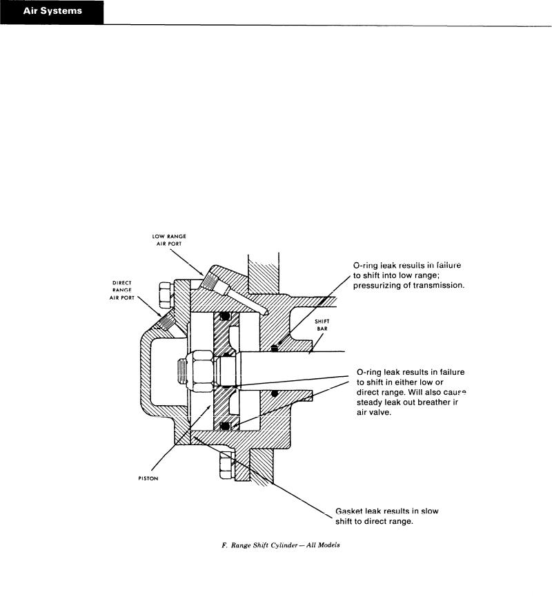
7. Range Shift Cylinder – Check Point E
If any of the seals in the range shift cylinder are defective the range shift will be affected. The degree of lost air, of course, will govern the degree of failure, from slow shift to complete failure to shift.
Refer to Illustration F for location of seals. Make sure cylinder bore is clean to prevent damage to piston seal. Use only a very light amount of shellac or Permatex on cover gasket to prevent clogging cylinder. Tighten cover capscrews securely.
22

Hole-Gear Air System
RT-12515 and RTO-12515 Transmissions
The following checks are to be made with normal vehicle air pressure but with the engine off. It is assumed air lines have been checked for leaks and the air regulator has been checked and the correct reading obtained. Refer to Illustrat on B for check points.
1.Air Input – Check Point F
With gearshift lever in neutral and normal vehicle air pressure, loosen the connection at input (end port) of the deep reduction valve until it can be determined that there is a constant flow of air at this point. Reconnect line.
If there is no air at this point, there is a restriction in the line between the deep reduction valve and air valve. Also check to make sure this line is connected to constant supply.
2.Deep Reduction Valve – Check Point G
With the deep reduction valve lever to “IN”, remove the line from the deep reduction valve at the port in holegearshift cylinder; there should be no air at this point.
Move the deep reduction valve lever to “OUT”. There should now be a constant air flow from line. Move lever to “IN” to shut off air. If the above conditions do not exist, deep reduction valve is faulty or there is a restriction in air line.
3. Hole-Gearshift Cylinder – Check Point H
If any of the seals in the hole-gearshift cylinder are defective the hole-gearshift will be affected. The degree of lost air, of course, will govern the degree of failure, from slow shift to complete failure to shift.
Refer to Illustration G, for location of seals
Leak at seal A . . . . Failure to engage hole-gear; pressurizing of transmission; hole-gear can be disengaged.
Leak at seal B.... Failure to engage hole-gear; leak from deep reduction valve exhaust port when valve is “IN”.
G. Cutaway. Deep Reduction Shift Cylinder. (R T-12515 models)
23

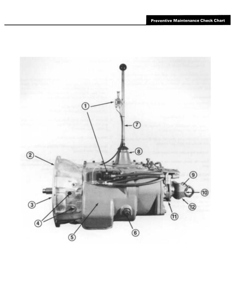
Preventive Maintenance Check Chart
CHECKS WITHOUT PARTIAL
DISASSEMBLY OF
CHASSIS OR CAB
1.Air System and Connections
a.Check for leaks, worn air lines, loose connections and capscrews. See Air Systems.
2.Clutch Housing Mounting
a.Check all capscrews in bolt circle of clutch housing for looseness. Tighten to recommended torque.
3.Clutch Release Bearing
a.Remove hand hole cover and check radial and axial clearance in release bearing.
b.Check relative position of thrust surface of release bearing with thrust sleeve on push type clutches.
4.Clutch Pedal Shaft and Bores
a.Pry upward on shafts to check wear.
b.If excessive movement is found, remove clutch release mechanism and check bushings in bores and wear on shafts.
5.Gear Lubricant
a.Change at specified service intervals.
b.Use only gear oils as recommended. See Lubrication section.
6.Filler and Drain Plugs
a.Remove filler plug and check level of lubricant at specified intervals. Tighten filler and drain plugs securely.
7.Gear Shift Lever
a.Check for looseness and free play in housing. If lever is loose in housing, proceed with Check No. 8.
8.Gearshift Lever Housing Assembly
a.Remove air lines at air valve and remove the gearshift lever housing assembly from transmission.
b.Check tension spring and washer for set and wear.
c.Check the gearshift lever pivot pin and pivot pin slot for wear.
d.Check bottom end of gearshift lever for wear and check slot of yokes and blocks in shift bar housing for wear at contact points with shift lever.
CHECKS WITH DRIVE LINE
DROPPED
9.Universal Joint Companion Flange Nut
a. Check for tightness. Tighten to recommended torque.
CHECKS WITH UNIVERSAL JOINT
COMPANION FLANGE REMOVED
10.Splines on Output Shaft
a.Check for wear from movement and chucking action of the universal joint companion flange.
11.Mainshaft Rear Bearing Cover
a.Check oil seal for wear.
12.Output Shaft
a.Pry upward against output shaft to check radial clear ante in mainshaft rear bearing.
24

Special Procedure For
Clutch (Input) Shaft
In some cases in field repair it may benecessary to replace only the input shaft due to clutch wear on the splines.
In these instances the input shaft can be removed without disassembling the transmission other than removing the shifting bar housing. Removal of the clutch housing is optional. Following is the detailed procedure:
Disassembly
1.Remove gearshift lever housing and shift bar housing from transmission.
2.Remove the front bearing cover.
3.Engage the mainshaft sliding clutches in two gears and remove the drive gear bearing nut.
4.Move the drive gear assembly as far forward as possible and remove the drive gear bearing.
5.Remove the washer from input shaft.
6.From the front, remove the snap ring from ID of drive gear.
7.Pull the input shaft forward and from splines of drive gear.
Reassembly
1.Install new input shaft into splines of drive gear just far enough to expose snap ring groove in ID of drive gear. Make sure that the bushing is installed in the pocket  the input shaft.
2.Install snap ring in ID of drive gear.
3.Install washer on shaft.
4. Move the fourth-fifth speed sliding clutch gear forward to contact end of input shaft  hub of drive gear. Block between rear of sliding clutch and front of the fourth speed gear. When installing bearing this will hold input shaft in position to seat the bearing properly.
5.Install drive gear bearing on shaft and into case bore, making sure blocking remains in place.
6.Remove blocking from mainshaft and install the drive gear bearing nut, left-hand thread. Use Loctite sealant on threads of nut and shaft.
7.Peen nut into milled slots in shaft.
8.Re-install front bearing cover, shifting bar housing and gearshift lever housing.
NOTE: 7%e above instructions are for changing the input shaft only. To change the drive gear, complete disassembly of the fron t section must be made.
26

General Precautions for Disassembly
IMPORTANT: Read this section before starting
the detailed disassembly procedures.
[t is assumed in the detailed disassembly instructions that the lubricant has been drained from the transmission, the necessary linkage and air lines removed and the transmission has been removed from the chassis. Removal of the gearshift lever housing assembly is included in the detailed instructions; however, this assembly must also be removed from transmission before removing unit from vehicle.
On RT-12515 and RTO-I2515 models, air lines from the hole-gear switch in cab must be disconnected at the transmission before removing unit from vehicle.
Follow each procedure closely in each section, making use of both the text and pictures.
1.BEARINGS Carefully wash and relubricate all bearings as removed and protectively wrap until ready for use. Remove all bearings with pullers designed for this purpose -- do not remove bearings with hammer and punch.
2.SNAP RINGS Remove snap rings with pliers designed for this purpose. Rings removed in this manner can be reused.
3.INPUT SHAFT The clutch or input shaft can be removed on most models without removing the countershaft, mainshaft or drive gear. See page 26.
4.CLEANLINESS Provide a clean place to work. It is important that no dirt or foreign material enters the unit during repairs. The outside of the unit should be care- fully cleaned before starting the disassembly. Dirt is abrasive and can damage highly polished parts such as bearings, sleeves and bushings.
5.WHEN DRIVING Apply force to shafts, housings, etc., with restraint. Movement of some parts is restricted. Do not apply force after the part being driven stops solidly. Use soft hammers and bars for all disassembly work.
27

1. Shifting Controls.
2 8
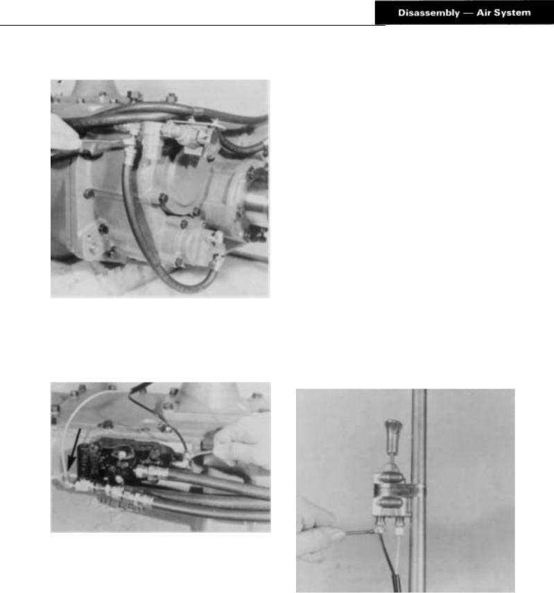
A. Removal of the Deep Reduction Shift Air System D RT-12515 Series
1.Remove the 1/4" ID air line between the deep reduction shift cylinder and the tee fitting forward of the filter / regulator assembly.
B.Removal of the Range Shift Air System
1.Disconnect the black and white 1/8" OD air line at the air valve on the side of the transmission.
NOTE: The gear shift lever housing, range control valve and lines may now be removed as a unit by turning out the four capscrews at the base of the gear shift lever housing.
2.Disconnect the black and white 1/8" O D air line at the range control valve on the shift lever.
29
 Loading...