

Page 1

Service Manual
Eaton Gen III Automated
Transmissions
TRSM0930 EN-US
May 2013
UltraShift®
AutoShift®
UltraShift® PLUS Linehaul Active Shifting (LAS)
UltraShift® PLUS Linehaul Small Step Efficiency (LSE)
UltraShift® PLUS Multipurpose Extreme Performance (MXP)
UltraShift® PLUS Multipurpose High Performance (MHP)
UltraShift® PLUS Vocational Active Shifting (VAS)
UltraShift® PLUS Vocational Construction Series (VCS)
UltraShift® PLUS Vocational High Performance (VHP)
UltraShift® PLUS Vocational Multipurpose Series (VMS)
UltraShift® PLUS Vocational Extreme Performance (VXP)
UltraShift® PLUS Passenger Vehicle (PV)
Page 2

TRTS0930 General Information |
Model:
F-5405B-DM3
F-6405B-DM3
F-14E316B-LSE
F-15E316B-LSE
F-17E316B-LSE
FM-15E316B-LSE
FM-14D310B-LST
FM-15D310B-LST
FO-16D313E-LEP
FO-5406B-DM3
FO-6406A-AW3
FO-6406B-AW3
FO-8406A-AW3
FOM-16D313E-LEP
RTLO-14918A-AS3
RTLO-16913L-DM3
RTLO-16918A-AS3
RTO-10910B-DM3
RTO-12910B-AS3
RTO-12910B-DM3
RTO-14910B-AS3
RTO-14910B-DM3
RTO-14910C-AS3
RTO-16910B-AS3
RTO-16910B-DM3
RTO-16910C-AS3
RTO-18910B-AS3
FO-10E310C-VAS
FO-12E310C-VAS
FO-14E310C-VAS
FO-16E310C-VAS
FOM-14E310C-VAS
F-5505B-DM3
F-6505B-DM3
RTLO-18918A-AS3
RTLO-20918A-AS3
RTLO-22918A-AS3
RTLOM-16913L-DM3
RTO-10910B-AS3
RTOM-16910B-DM3
FO-14E310C-LAS
FO-16E310C-LAS
FO-18E310C-LAS
FOM-14E310C-LAS
FOM-15E310C-LAS
FOM-16E310C-LAS
FM-14E310B-LAS
FM-15E310B-LAS
EO-11E406B-PV
FOM-15E310C-VAS
FOM-16E310C-VAS
FO-10E308LL-VCS
FO -11E308LL-VC S
FO-12E308LL-VCS
FO-14E308LL-VCS
FO-16E308LL-VCS
FO-17E308LL-VCS
FO-16E313A-VHP
FO-18E313A-VHP
FO-20E313A-VHP
FO -10E309A LL-VMS
FO -11E309AL L-VMS
FO -12E309ALL-VMS
FO -14E30 9ALL-VM S
FO -16E309ALL-VMS
FO -17E309ALL-VMS
FO-14E313B-MHP
FO-16E313B-MHP
FO-18E313B-MHP
FO-20E313B-MHP
FO-14E318B-MXP
FO-16E318B-MXP
FO-18E318B-MXP
FO-20E318B-MXP
FO-22E318B-MXP
FO-14E318B-VXP
FO-16E318B-VXP
FO-18E318B-VXP
FO-20E318B-VXP
FO-22E318B-VXP
FO-22E318B-VXP
EO-11E406B-PVER
EO-11E406B-PVHR
EO-11E406B-PV
2013.05.30
© 2013 Eaton. All rights reserved
1
Page 3

TRSM0930 Table of Contents |
Table of Contents
General Information
Warnings & Cautions. . . . . . . . . . . . . . . . . . . . . . . . . . .1
How to use this Manual . . . . . . . . . . . . . . . . . . . . . . . . . 2
Transmission Overview . . . . . . . . . . . . . . . . . . . . . . . . . 3
Serial Tag Information and Model Nomenclature. . . . .15
Clutch Greasing Guidelines . . . . . . . . . . . . . . . . . . . . .19
Grease Interval Count Reset. . . . . . . . . . . . . . . . . 19
ServiceRanger Procedure . . . . . . . . . . . . . . . . . . 20
Operator Triggered Procedure . . . . . . . . . . . . . . . 22
Service Procedure
Thread-In ECA Speed Sensor. . . . . . . . . . . . . . . . . . . .23
Electronic Clutch Actuator (ECA) . . . . . . . . . . . . . . . . . 27
Low Capacity Inertia Brake . . . . . . . . . . . . . . . . . . . . . 31
Release Yoke and Cross-shaft(s). . . . . . . . . . . . . . . . .35
Cobra Lever . . . . . . . . . . . . . . . . . . . . . . . . . . . . . . . . . 41
Shift Control . . . . . . . . . . . . . . . . . . . . . . . . . . . . . . . .45
Medium-Duty Transmission Harness. . . . . . . . . . . . . .49
Heavy-Duty Transmission Harness . . . . . . . . . . . . . . .53
Medium-Duty Transmission Electronic Control Unit (TE-
CU) . . . . . . . . . . . . . . . . . . . . . . . . . . . . . . . . . . . . . . . 57
Heavy-Duty Transmission Electronic Control Unit (TECU)
61
Electric Shifter . . . . . . . . . . . . . . . . . . . . . . . . . . . . . . .65
Medium-Duty Inertia Brake . . . . . . . . . . . . . . . . . . . . . 69
Air Filter Regulator. . . . . . . . . . . . . . . . . . . . . . . . . . . .75
Heavy-Duty Inertia Brake . . . . . . . . . . . . . . . . . . . . . . . 79
Combination Valves (Range and Deep Reduction). . . . 83
Range Valve. . . . . . . . . . . . . . . . . . . . . . . . . . . . . . . . .87
Splitter Valve . . . . . . . . . . . . . . . . . . . . . . . . . . . . . . . .91
Directional Output Shaft Speed Sensor . . . . . . . . . . . .95
Park Actuator Assembly. . . . . . . . . . . . . . . . . . . . . . . .99
Park Pawl Position Sensor. . . . . . . . . . . . . . . . . . . . .103
Medium-Duty Output Shaft Speed Sensor. . . . . . . . .107
Heavy-Duty Output Shaft Speed Sensor . . . . . . . . . . 111
Main Shaft Speed Sensor . . . . . . . . . . . . . . . . . . . . . 115
Medium-Duty Input Shaft Speed Sensor . . . . . . . . . .119
Heavy-Duty Input Shaft Speed Sensor. . . . . . . . . . . . 123
Rail Select Sensor . . . . . . . . . . . . . . . . . . . . . . . . . . . 127
Gear Select Sensor . . . . . . . . . . . . . . . . . . . . . . . . . .131
Lubricant Filter (AW3 Models Only). . . . . . . . . . . . . .135
Appendix
Operation and Basic Troubleshooting . . . . . . . . . . . . 139
Inspection Procedures. . . . . . . . . . . . . . . . . . . . . . . . 140
Lubrication Specifications . . . . . . . . . . . . . . . . . . . . . 141
UltraShift DM3 and AutoShift AS3 . . . . . . . . . . . 141
Buy From a Reputable Dealer. . . . . . . . . . . . . . . 141
Transmission Operating Angles . . . . . . . . . . . . . 141
Operating Temperatures with Oil Coolers . . . . . . 141
UltraShift™ ASW Models . . . . . . . . . . . . . . . . . . 141
Buy From a Reputable Dealer. . . . . . . . . . . . . . . 142
Synthetic Dextron III ATF . . . . . . . . . . . . . . . . . . 142
CD-50. . . . . . . . . . . . . . . . . . . . . . . . . . . . . . . . . 142
Maintenance and Lubricant Change Intervals . . 142
Checking Wet Clutch Lubricant . . . . . . . . . . . . . 142
Proper Wet Clutch Lubricant Level. . . . . . . . . . . 142
Checking Gearbox Lubricant . . . . . . . . . . . . . . . 142
Cooler . . . . . . . . . . . . . . . . . . . . . . . . . . . . . . . . 142
Proper Gearbox Lubricant Level. . . . . . . . . . . . . 142
Drain the Transmission Gearbox and Wet Clutch
Housing . . . . . . . . . . . . . . . . . . . . . . . . . . . . . . . 143
Change Wet Clutch Filters . . . . . . . . . . . . . . . . . 143
Fill the Transmission . . . . . . . . . . . . . . . . . . . . . 143
Clutch Calibration. . . . . . . . . . . . . . . . . . . . . . . . 143
Maintenance and Lubricant Change Intervals . . . . . . 144
Checking Wet Clutch Lubricant . . . . . . . . . . . . . 144
Proper Wet Clutch Lubricant Level. . . . . . . . . . . 144
Checking Gearbox Lubricant . . . . . . . . . . . . . . . 144
Cooler . . . . . . . . . . . . . . . . . . . . . . . . . . . . . . . . 144
Proper Gearbox Lubricant Level. . . . . . . . . . . . . 144
Drain the Transmission Gearbox and Wet Clutch
Housing . . . . . . . . . . . . . . . . . . . . . . . . . . . . . . . 145
Change Wet Clutch Filters . . . . . . . . . . . . . . . . . 145
Fill the Transmission . . . . . . . . . . . . . . . . . . . . . 145
Clutch Calibration. . . . . . . . . . . . . . . . . . . . . . . . 145
Tool Specifications . . . . . . . . . . . . . . . . . . . . . . . . . .146
General Tools . . . . . . . . . . . . . . . . . . . . . . . . . . . 146
Torque Specifications . . . . . . . . . . . . . . . . . . . . . . . . 147
Torque Overview . . . . . . . . . . . . . . . . . . . . . . . . 149
Grade Sensor Calibration. . . . . . . . . . . . . . . . . . . . . . 152
ServiceRanger Procedure . . . . . . . . . . . . . . . . . 152
Operator-Triggered Procedure . . . . . . . . . . . . . . 154
2013.05.30
© 2013 Eaton. All rights reserved
i
Page 4

Warnings & Cautions | General Information TRSM0930
!
!
!
!
!
!
!
!
Warnings & Cautions
Warning: Follow the specified procedures in the indicated
order to avoid personal injury.
Note: Additional relevant information not covered in the
service procedure.
Warning: Before starting a vehicle:
• Ensure adequate fuel level.
• Sit in the driver's seat.
• Place shift lever in neutral.
• Set the parking brake.
Warning: Before working on a vehicle or leaving the cab
with engine running:
• Ensure ignition is off while hands are within the
clutch housing area.
• Place shift lever in neutral.
• Set the parking brake.
• Block the wheels.
Warning: When parking the vehicle or leaving the cab:
• Place shift lever in neutral.
• Set the parking brake.
Caution: Follow the specified procedures in the indicated
order to avoid equipment malfunction or damage.
Caution: Do not release the parking brake or attempt to
select a gear until the air pressure is at the correct
level.
Caution: To avoid damage to the transmission during tow-
ing:
• Place shift lever in neutral.
• Lift the drive wheels off of the ground or disconnect the driveline.
Caution: Do not operate the vehicle if alternator lamp is lit
or if gauges indicate low voltage.
1
© 2013 Eaton. All rights reserved
2013.05.30
Page 5

For parts or service call us
Pro Gear & Transmission, Inc.
1 (877) 776-4600
(407) 872-1901
parts@eprogear.com
906 W. Gore St.
Orlando, FL 32805
Page 6

TRSM0930 General Information | How to use this Manual
How to use this Manual
This publication is divided into three sections General Information, Service Repair Procedures and the Appendix.
General Information
This section contains the basic chapters like “Transmission
Overview,” “How to Use This Manual” and “Serial Tag and
Model Nomenclature.”
Service Repair Procedures
A “Components Identification” diagram is included at the
beginning of each procedure for disassembly, assembly,
removal and installation. Below the “Components Identifi
cation” diagram is a numerical listing for each part with the
part name.
Appendix
This section contains information like: “Operation,” “Lubrication Specifications,” “Inspection” (in base box manuals),
“Powerflow” (in base box manuals), “Air System Opera
tion” and “Troubleshooting” (in base box manuals), “Basic
Troubleshooting” (in base box manuals), “Tool Specifica
tions,” “Torque Specifications,” and the “Torque Overview.”
-
-
-
The service procedures in this manual are for transmission
automation components only. To find the information you
need, simply locate the procedure in the “Table of Con
tents,” turn to the page specified and follow the procedure.
If you are unsure of a components’ name, you can refer
ence the “Transmission Overview” pages.
To service the mechanical portion of the transmission system, refer to the specific transmission service manual.
-
-
2013.05.30
© 2013 Eaton. All rights reserved
2
Page 7
Transmission Overview | General Information TRSM0930
Transmission Overview
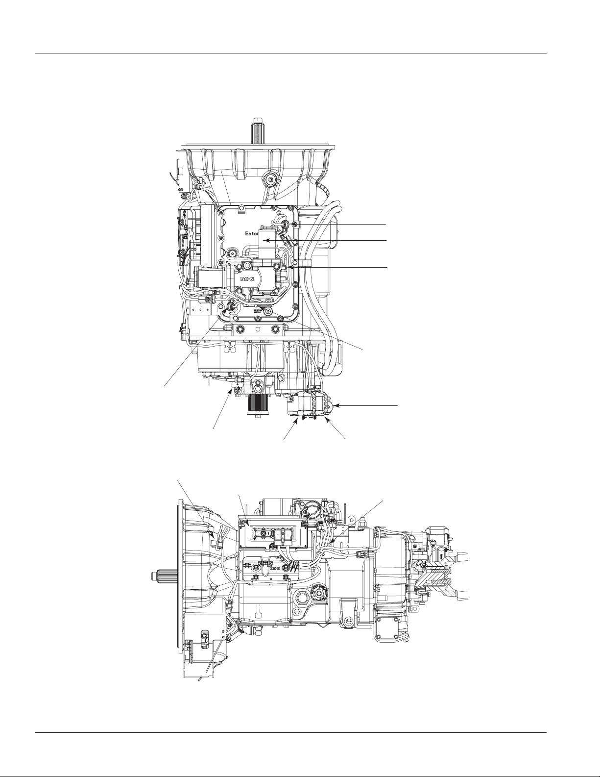
Heavy-Duty 8LL / VCS & 9ALL / VMS
Input Shaft Speed Sensor
Electric Shifter
Gear Selector Sensor
Mainshaft
Speed Sensor
Output Shaft
Speed Sensor
Flywheel Speed Sensor
(Shipping Location)
Transmission
ECU
Range
(Combination Valve)
Rail Selector Sensor
Air Filter
Regulator
Deep Reduction
Transmission
Harness
3
© 2013 Eaton. All rights reserved
2013.05.30
Page 8
TRSM0930 General Information | Transmission Overview
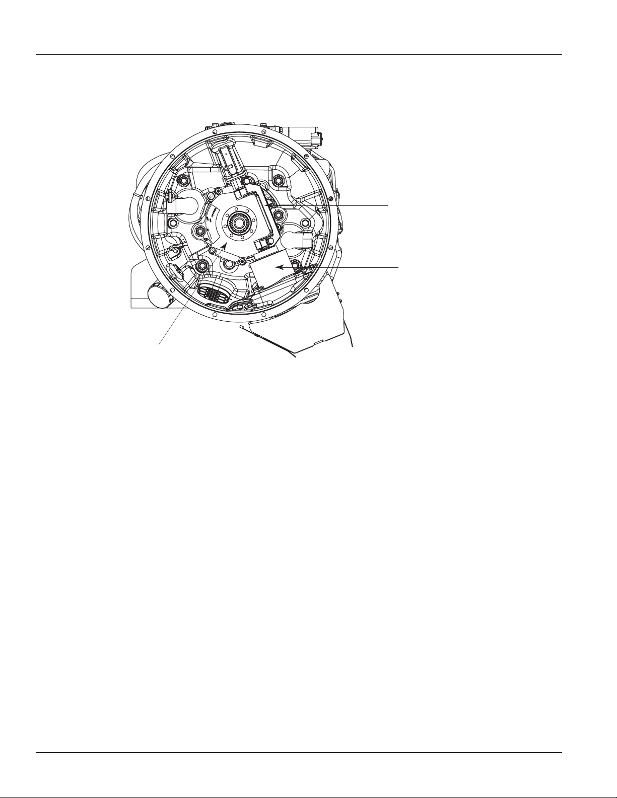
Heavy-Duty 8LL / VCS & 9ALL / VMS
Release Yoke and
Cross-shaft Assembly
Electronic Clutch
Actuator (ECA)
Low Capacity
Inertia Brake (LCIB)
2013.05.30
© 2013 Eaton. All rights reserved
4
Page 9
Transmission Overview | General Information TRSM0930
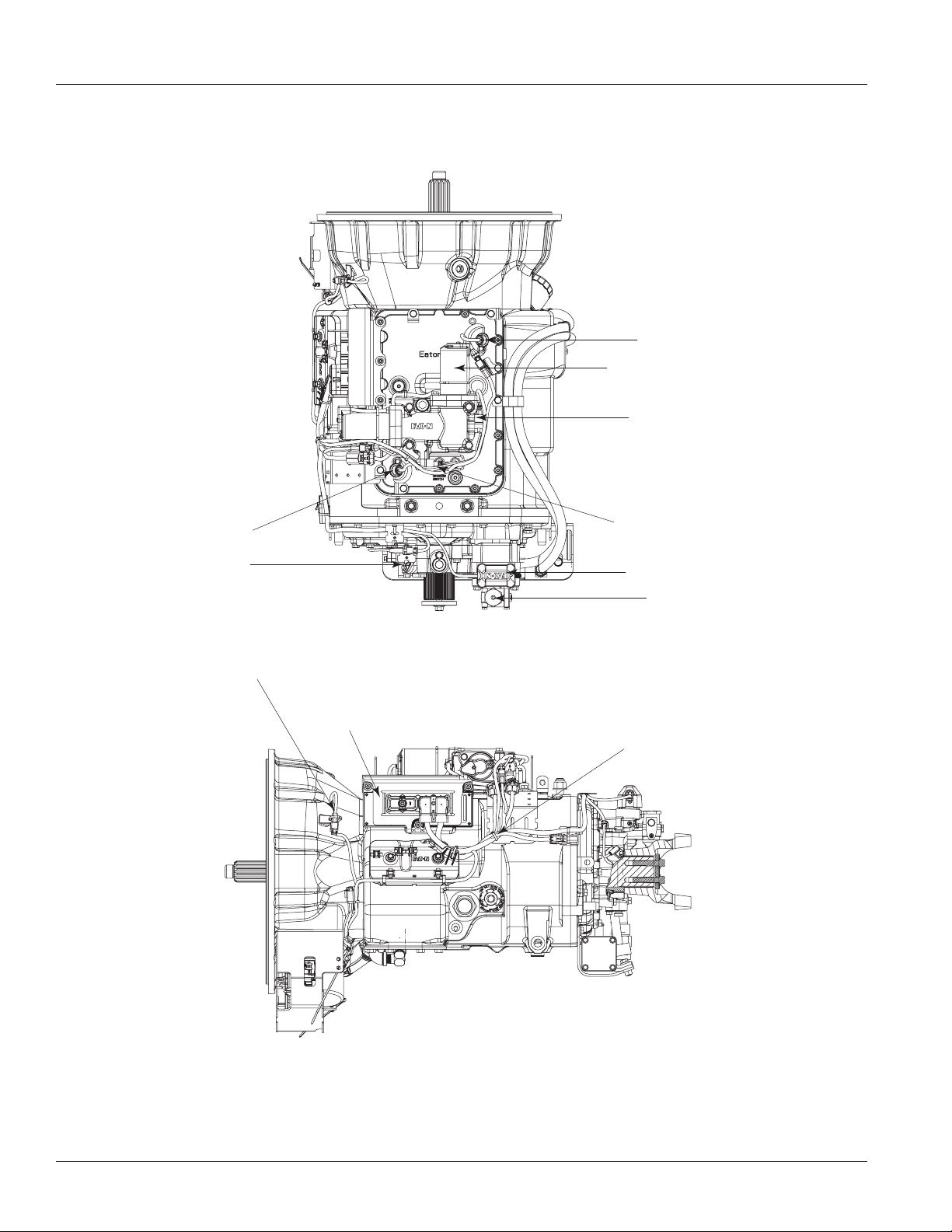
Heavy-Duty 10-Speed LAS/VAS
Input Shaft Speed Sensor
Electric Shifter
Gear Select Sensor
Main Shaft
Speed Sensor
Output Shaft
Speed Sensor
Flywheel Speed Sensor
(Shipping Location)
Rail Select Sensor
Range Valve Solenoid
Air Filter Regulator
Transmission ECU
Transmission Harness
5
© 2013 Eaton. All rights reserved
2013.05.30
Page 10

TRSM0930 General Information | Transmission Overview
Heavy-Duty 10-Speed LAS/VAS
Release Yoke and
Cross-shaft Assembly
Electronic Clutch
Actuator (ECA)
Low Capacity
Inertia Brake (LCIB)
2013.05.30
© 2013 Eaton. All rights reserved
6
Page 11
Transmission Overview | General Information TRSM0930
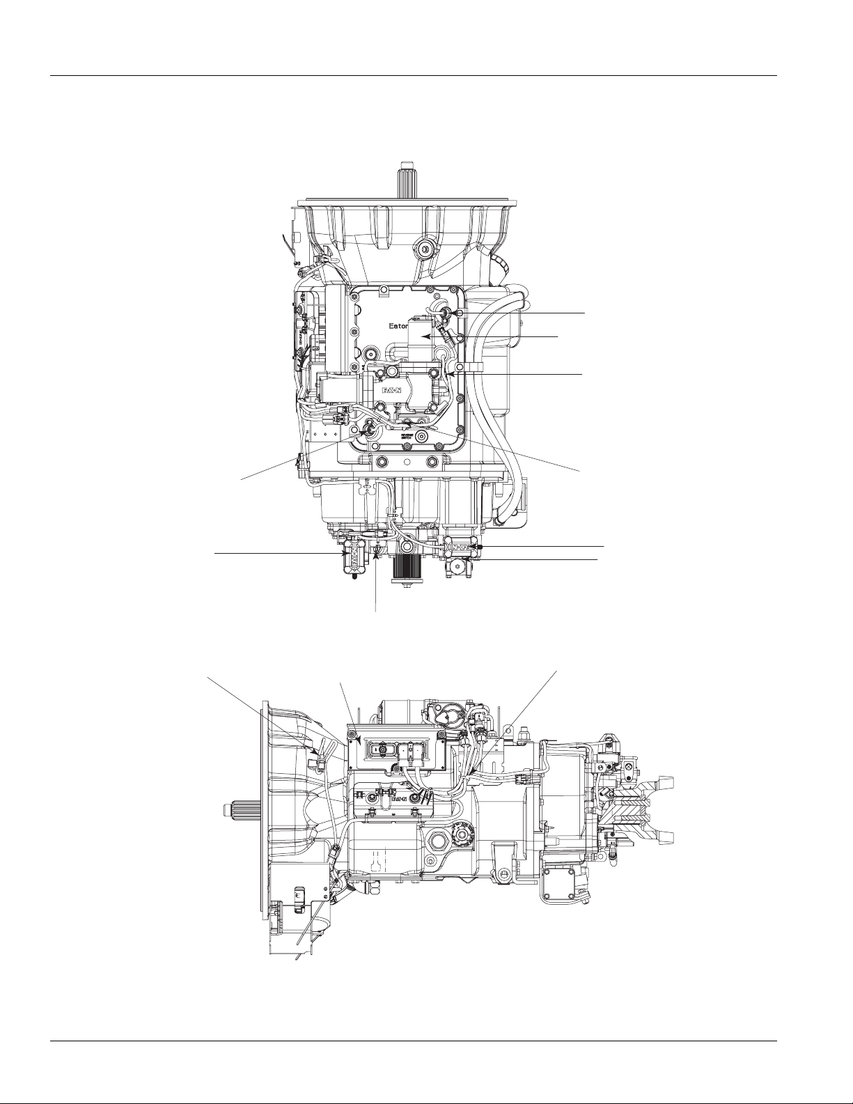
Heavy-Duty 13-Speed MHP/VHP, 16-Speed LSE
& 18-Speed VXP/MXP
Input Shaft Speed Sensor
Electric Shifter
Gear Select Sensor
Mainshaft
Speed Sensor
Splitter Valve
Solenoid
Flywheel S
(Shipping Location)
peed Sensor
Rail Select Sensor
Range Valve Solenoid
Air Filter Regulator
Output Shaft
Speed Sensor
Transmission Harness
Transmission ECU
7
© 2013 Eaton. All rights reserved
2013.05.30
Page 12

TRSM0930 General Information | Transmission Overview
Heavy-Duty 13-Speed MHP/VHP, 16-Speed LSE
& 18-Speed VXP/MXP
Release Yoke and
Cross-shaft Assembly
Electronic Clutch
Actuator (ECA)
Low Capacity
Inertia Brake (LCIB)
2013.05.30
© 2013 Eaton. All rights reserved
8
Page 13

Transmission Overview | General Information TRSM0930
Heavy-Duty 13-Speed DM3 & 18-Speed AS3
Input Shaft
Speed Sensor
Electric Shifter
Gear Select Sensor
Main Shaft
Speed Sensor
Splitter Valve Solenoid
Transmission ECU
Rail Select Sensor
Range Valve Solenoid
Air Filter Requlator
Output Shaft Speed Sensor
Transmission Harness
Inertia Brake
(13-Speed DM3 Only)
9
© 2013 Eaton. All rights reserved
2013.05.30
Page 14

TRSM0930 General Information | Transmission Overview
Air Filter Regulator
Range Valve Solenoid
Rail Select Sensor
Gear Select Sensor
Electric Shifter
Input Shaft
Speed Sensor
Output Shaft
Speed Sensor
Main Shaft
Speed Sensor
Transmission ECU
Inertia Brake
(10-Speed DM3 Only)
Transmission Harness
Heavy-Duty 10-Speed AS3 & DM3
2013.05.30
© 2013 Eaton. All rights reserved
10
Page 15

Transmission Overview | General Information TRSM0930
Output Shaft
Speed Sensor
Rail Select Sensor
Gear Select Sensor
Electric Shifter
Transmission ECU
Inertia Brake
Input Shaft
Speed Sensor Location
Transmission Harness
Medium-Duty 6 & 5-Speed DM3
11
© 2013 Eaton. All rights reserved
2013.05.30
Page 16

TRSM0930 General Information | Transmission Overview
Electric Shifter
Gear Select Sensor
Rail Select Sensor
Output Shaft
Speed Sensor
Transmission ECU
Inertia Brake
Input Shaft
Speed Sensor Location
Wetclutch Solenoid
Connector
Oil Pan and Filters
Transmission Harness
Medium-Duty 6-Speed AW3
2013.05.30
© 2013 Eaton. All rights reserved
12
Page 17

Transmission Overview | General Information TRSM0930
Medium-Duty 6-Speed PV
Electric Shifter
Transmission ECU
Gear Select
Sensor
Rail Select
Sensor
Output Shaft
Speed Sensor
Transmission
Harness
Inertia
Brake
Input Shaft
Speed Sensor
13
© 2013 Eaton. All rights reserved
2013.05.30
Page 18

TRSM0930 General Information | Transmission Overview
ECA
Electronic Clutch
Actuator (ECA)
Release Yoke
& Cross-Shaft
Assembly
Medium-Duty 6-Speed PV
2013.05.30
© 2013 Eaton. All rights reserved
14
Page 19

Serial Tag Information and Model Nomenclature | General Information TRSM0930
Model
Serial
Eaton
Transmissions
R
Made In
RTLO-16913L-DM3
Eaton Corporation
Transmission Div.
Kalamazoo, MI. 49003
Fuller
R
Serial Tag Information and Model Nomenclature
Transmission model designation and other transmission
identification information are stamped on the serial tag. To
identify the transmission model and serial number, locate
the tag on the transmission and then locate the numbers as
shown. The figure below shows the tag location for these
transmissions.
When calling for service assistance or parts, have the
model and serial numbers handy.
Do not remove or destroy the transmission identification
tag!
Serial Number
The serial number is the sequential identification number of
the transmission. Before calling for service assistance,
write the number down as it may be needed.
Bill of Material or Customer Number
This number may be located below the model and serial
numbers. It is a reference number used by Eaton®.
Model Number
The model number gives basic information about the transmission and is explained below. Use this number when calling for service assistance or replacement parts.
15
© 2013 Eaton. All rights reserved
2013.05.30
Page 20

TRSM0930 General Information | Serial Tag Information and Model Nomenclature
R
Roadranger
Twi n Countershaft
Overdrive
TO-
Torque x 100
Design Level
Generation 3 Electronics
Gear Ratio
Forward Speeds
1X 10⁹ X-
DM3
10-Speed
Automatic
w/DM Autoclutch
Roadranger
Twi n Countershaft
Overdrive
Torque x 100
Design Level
R T O -1X 9 10 X-AS3
Generation 3 Electronics
AutoShift
Gear Ratio
Forward Speeds
F
Fuller
Overdrive
- 3
Torque x 100
Design Level
Generation 3 Electronics
Gear Ratio
Forward Speeds
X406X-DM
Automatic
w/DM Autoclutch
X
Roadranger
Twi n Countershaft
Low-Inertia
Overdrive
R T L O M-1X9 13 X-DM3
Gen 3 Electronics
Automatic w/DM Autoclutch
Gear Ratio
Forward Speeds
Design Level
Torque x 100
1750 lb.ft. Torque in
Top Two Gears Only
3
Fuller
Overdrive
Torque x 100
Design Level
Automatic with WetClutch
Gear Ratio
Forward Speeds
FX X 064-
X-
A W
Generation 3 Electronics
10-Speed
6-Speed
6-Speed
13-Speed
F
Fuller
Overdrive
- 3
Torque x 100
Design Level
Generation 3 Electronics
Gear Ratio
Forward Speeds
X405X-DM
Automatic
w/DM Autoclutch
X
5-Speed
Roadranger
Twi n Countershaft
Low-Inertia
Overdrive
R T L O-1X9 18 X-AS 3
Gen 3 Electronics
AutoShift
Gear Ratio
Forward Speeds
Design Level
Torque x 100
18-Speed
Transmission Tag
2013.05.30
© 2013 Eaton. All rights reserved
16
Page 21

Serial Tag Information and Model Nomenclature | General Information TRSM0930
6-Speed
10-Speed
10-Speed
Brand - Eaton
Overdrive
Nominal Torque Lb. Ft.
Nominal Torque Lb. Ft.
X 100 + 50
Configuration
Design Level
Mechicanical & Electronic
Brand - Fuller
Overdrive
Nominal Torque Lb. Ft.
X 100 + 50
Starting Device
(Clutch Type)
Design Level
Mechicanical & Electronic
Brand - Fuller
Overdrive
Multi-Torque
X 100 + 50
Starting Device
(Clutch Type)
Design Level
Mechicanical & Electronic
E
O
F
F
O
1XE406 B
-
O
M
1XE308 LL-
-
1XE310 C-
PV
Passenger
Vehicle
Ratio Set
Number of Speeds
VCS
Construction
Series
UltraShift
Vocational
Ratio Set
Number of Speeds
LAS
Active
Shifting
UltraShift
Line Haul
Ratio Set
Number of Speeds
10-Speed
11-Speed
13-Speed
Brand - Fuller
Overdrive
Multi-Torque
Nominal Torque Lb. Ft.
Nominal Torque Lb. Ft.
X 100 + 50
Starting Device
(Clutch Type)
Design Level
Mechicanical & Electronic
Brand - Fuller
Overdrive
X 100 + 50
Starting Device
(Clutch Type)
Design Level
Mechicanical & Electronic
Brand - Fuller
Overdrive
Nominal Torque Lb. Ft.
X 100 + 50
Starting Device
(Clutch Type)
Design Level
Mechicanical & Electronic
F
O
F
O
F
1XE310 C-
M
1XE309ALL-
-
O
1XE313A-
-
VAS
Active
Shifting
UltraShift
Vocational
Ratio Set
Number of Speeds
VMS
Mixer
Series
UltraShift
Vocational
Ratio Set
Number of Speeds
MHP
High Performance
UltraShift
Multipurpose
Ratio Set
Number of Speeds
17
© 2013 Eaton. All rights reserved
2013.05.30
Page 22

TRSM0930 General Information | Serial Tag Information and Model Nomenclature
F
Brand - Fuller
Overdrive
M
-
X 100 + 50
Nominal Torque Lb. Ft.
Starting Device
(Clutch Type)
UltraShift
Linehaul
Ratio Set
Number of Speeds
1XE316B-
LSE
Small Step
Efficiency
Design Level
Mechicanical & Electronic
16-Speed
F
Brand - Fuller
Overdrive
O
-
X 100 + 50
Nominal Torque Lb. Ft.
Starting Device
(Clutch Type)
UltraShift
Multipurpose
Ratio Set
Number of Speeds
1XE318 B-
MXP
Xtreme Performance
Design Level
Mechicanical & Electronic
18-Speed
F
Brand - Fuller
Overdrive
O
-
X 100 + 50
Nominal Torque Lb. Ft.
Starting Device
(Clutch Type)
UltraShift
Multipurpose
Ratio Set
Number of Speeds
1XE318 B-
MXP
Xtreme Performance
Design Level
Mechicanical & Electronic
F
Brand - Fuller
Overdrive
O
-
X 100 + 50
Nominal Torque Lb. Ft.
Starting Device
(Clutch Type)
UltraShift
Vocational
Ratio Set
Number of Speeds
1XE313A-
VHP
High Performance
Design Level
Mechicanical & Electronic
13-Speed
18-Speed
2013.05.30
© 2013 Eaton. All rights reserved
18
Page 23

Clutch Greasing Guidelines | General Information TRSM0930
!
Clutch Greasing Guidelines
Caution: It is highly important to follow proper clutch lube
intervals as specified in Lubrication Manual
TCMT0021. Failure to do so may result in clutch
failure and unnecessary repairs.
The heavy-duty ECA clutch housing has 2 grease fittings on
the lower right side. The upper port is marked “CS” for the
upper cross-shaft assembly, while the lower port is marked
“RB” for the release bearing.
For more detailed cross-shaft greasing information refer to
the Release Yoke and Cross-shaft Installation section of this
manual. Refer to Clutch Service Manual CLSM0200, for
release bearing greasing information.
ServiceRanger Procedure
Grease Interval Count Reset
The Heavy-Duty UltraShift PLUS has an optional prognostic
feature that notifies the operator when the Clutch Release
Bearing needs greasing. This feature can be enabled or dis
abled via ServiceRanger.
At the appropriate grease interval and shortly after each
engine start, “GI” will momentarily appear in the gear dis
play, along with an audible tone. This will continue to occur
at each engine start until clutch service has been com
pleted.
Note: “GI” stands for grease interval and may be misread
as “G1”on gear display.
The operator can choose to follow this automated lube
schedule or the published lube guidelines in the Lubrication
Manual TCMT0021. When enabled, it is highly important to
reset the grease interval count every time the Release Bear
ing is greased.
The grease interval count can be reset via ServiceRanger or
Operator-Triggered Special Function.
-
-
-
-
19
© 2013 Eaton. All rights reserved
2013.05.30
Page 24

TRSM0930 General Information | Clutch Greasing Guidelines
Operator Triggered Procedure
2013.05.30
© 2013 Eaton. All rights reserved
20
Page 25
Thread-In ECA Speed Sensor | Service Procedure TRSM0930
1
2
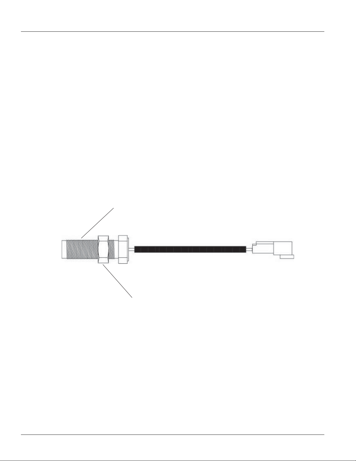
Thread-In ECA Speed Sensor
Special Instructions
None
Component Identification
Special Tools
Basic hand tools
23
1. Sensor
2. Jam Nut
© 2013 Eaton. All rights reserved
2013.05.30
Page 26
TRSM0930 Service Procedure | Thread-In ECA Speed Sensor
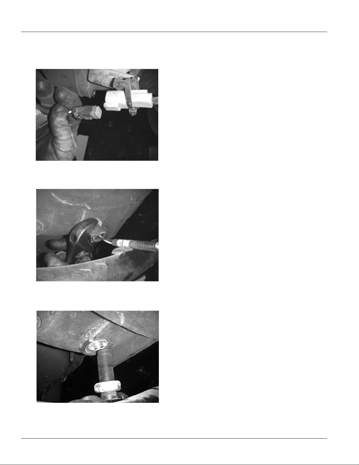
Procedure - Removal
1. Disconnect ECA Speed Sensor Connector.
2. Loosen jam nut on ECA.
3. Rotate sensor counterclockwise to remove it.
2013.05.30
© 2013 Eaton. All rights reserved
24
Page 27

Thread-In ECA Speed Sensor | Service Procedure TRSM0930
Procedure - Installation
1. Thread Speed Sensor into the Engine Bell Housing until
it touches the flywheel.
2. After the sensor touches the flywheel, rotate it counter-
clockwise 1/2 to 1 full turn.
3. Hold the sensor in place and tighten the 3/4”-16 jam
nut to 15 lb-ft. (20.3 Nm).
4. Apply included material to low-voltage 4-way harness
connector terminals.
Note: Apply just enough material to cover the end of
the terminal.
Note: Use only Eaton lubricant part number 5564527.
(Nye Lubricants NYOGEL 760G. For MSDS safety
or other information see www.nyelubri
-
cants.com).
5. Connect Engine Speed Sensor Connector to the mating
connector on the transmission and fasten harness, if
needed.
25
© 2013 Eaton. All rights reserved
2013.05.30
Page 28

TRSM0930 Service Procedure | Thread-In ECA Speed Sensor
2013.05.30
© 2013 Eaton. All rights reserved
26
Page 29

Electronic Clutch Actuator (ECA) | Service Procedure TRSM0930
Electronic Clutch Actuator (ECA)
Special Instructions
If vehicle is equipped with an 8-bolt PTO, removal may be
required prior to removing the ECA. Follow PTO manufac
turer’s guidelines for removal.
Component Identification
Special Tools
-
Basic hand tools
1. Bracket Cap Screw
2. ECA Cap Screw
3. ECA
4. 8-Way Connector
5. 3-Way Connector
6. ECA Shield (Optional)
27
© 2013 Eaton. All rights reserved
2013.05.30
Page 30

TRSM0930 Service Procedure | Electronic Clutch Actuator (ECA)
!
Procedure - Removal
Warning: Ensure the Hand Hole Cover is closed when
removing the ECA.
1. Disconnect the negative battery cable.
2. Disconnect the 8-way and 3-way connectors from the
ECA.
Note: Some models do not use a shield.
3. Remove the 4 cap screws from the ECA shield and
remove shield.
Note: Medium-duty models are mounted with 3 cap
screws and 1 lock nut.
4. Remove the 4 cap screws from the ECA mounting
flange.
5. Remove the ECA.
Note: The ECA has an alignment pin that requires the
unit to be rotated to exit the clutch housing bore.
Note: If ECA will not slide from the clutch housing after
all the fasteners are removed, use the available
pusher holes found on both sides of the ECA
casting. Place the included jackscrews into the
holes. Turn each jackscrew until it touches. Next,
turn the upper jackscrew 1 turn; then rotate to
the lower jackscrew and rotate it 1 turn. Continue
until the ECA is fully displaced from the bore.
2013.05.30
© 2013 Eaton. All rights reserved
28
Page 31

Electronic Clutch Actuator (ECA) | Service Procedure TRSM0930
Procedure - Installation
1. Install the ECA into the clutch housing bore. Align it
with the lower cross-shaft.
Note: The ECA will have to be rotated to align with the
slot in the Clutch Housing.
Note: Ensure you rotate the Release Yoke as close to
the Case Dowel in the Clutch Housing prior to
mating with the cross-shaft. This allows the
Release Yoke to clear the Release Bearing during
installation.
2. Install the 4 cap screws from the ECA Mounting Flange.
Tighten them to 35-45 lb-ft. (47-61 Nm).
3. If applicable, install the 4 cap screws for the ECA
shield. Tighten them to 35-45 lb-ft. (47-61 Nm).
4. Apply NyoGel to terminals and reconnect the 8-way
and 3-way connectors to the ECA.
Note: Apply just enough material to cover the end of
the terminal.
Note: Use only Eaton lubricant part number 5564527
(Nye Lubricants NYOGEL 760G. For MSDS safety
or other information see www.nyelubri
-
cants.com.)
Note: Medium-duty models are mounted with 3 cap
screws and 1 lock nut. Tighten to 35-45 lb-ft. (47-61
Nm).
Note: The cap screws for the ECA are longer than the
ECA Bracket cap screws.
Note: Ensure the ECA does not bind on the cross-shaft
by snugging all cap screws before tightening to
the specified torque.
5. Reconnect the negative 12-volt battery cable.
6. If previously removed, install the 8-bolt PTO after ECA
installation. Follow the PTO manufacturer’s guidelines
for installation instructions.
29
© 2013 Eaton. All rights reserved
2013.05.30
Page 32

TRSM0930 Service Procedure | Electronic Clutch Actuator (ECA)
2013.05.30
© 2013 Eaton. All rights reserved
30
Page 33

Low Capacity Inertia Brake | Service Procedure TRSM0930
1
2
Low Capacity Inertia Brake
Special Instructions
None
Component Identification
Special Tools
Basic hand tools
1. Mounting Nut
2. Low Capacity Inertia Brake (LCIB)
31
© 2013 Eaton. All rights reserved
2013.05.30
Page 34

TRSM0930 Service Procedure | Low Capacity Inertia Brake
Procedure - Removal
Note: The Transmission and ECA must be removed prior to
removing the LCIB.
1. Remove the 2 mounting nuts with a breaker bar and
socket.
2. Remove the LCIB by hand by sliding off of the splined
Input Shaft.
2013.05.30
© 2013 Eaton. All rights reserved
32
Page 35

Low Capacity Inertia Brake | Service Procedure TRSM0930
Procedure - Installation
1. Slide the LCIB onto the splined Input Shaft while cen-
tering the holes onto the retaining studs.
2. Install the 2 retaining nuts and torque nuts to 140-150
lb-ft. (190-203 Nm).
Note: The LCIB can only be installed one way. The label
is toward the right side of the vehicle and facing
the flywheel.
33
© 2013 Eaton. All rights reserved
2013.05.30
Page 36

TRSM0930 Service Procedure | Low Capacity Inertia Brake
2013.05.30
© 2013 Eaton. All rights reserved
34
Page 37

Release Yoke and Cross-shaft(s) | Service Procedure TRSM0930
Release Yoke and Cross-shaft(s)
Special Instructions
None
Component Identification
Special Tools
Basic hand tools
1
2
3
4
5
1. Plug
2. O-ring
3. Upper Cross-shaft
4. Bushing
5. Seal
6. Lock Washer
7. Mounting Screw
8. Release Yoke
9. Lower Cross-shaft
6
7
8
9
35
© 2013 Eaton. All rights reserved
2013.05.30
Page 38

TRSM0930 Service Procedure | Release Yoke and Cross-shaft(s)
Procedure - Removal
Note: The Transmission and ECA must be removed prior to
removing the Release Yoke and Cross-shaft(s).
1. Remove the upper and lower Cross-Shaft Mounting
cap screws and lock washers from the Release Yoke.
2. Remove the lower Cross-Shaft and Release Yoke.
3. Remove the upper Cross-Shaft.
4. If necessary, remove the Cross-Shaft Plug with o-ring.
2013.05.30
5. If necessary, remove the upper Cross-Shaft Seal
© 2013 Eaton. All rights reserved
assembly.
36
Page 39

Release Yoke and Cross-shaft(s) | Service Procedure TRSM0930
6. If necessary, remove the 2 upper Cross-Shaft bush-
ings.
37
© 2013 Eaton. All rights reserved
2013.05.30
Page 40

TRSM0930 Service Procedure | Release Yoke and Cross-shaft(s)
Procedure - Installation
1. If previously removed, install the 2 upper Cross-shaft
bushings.
Note: Make sure to apply grease to the bushings.
2. If previously removed, install the upper Cross-shaft
grease seal.
3. If previously removed, install the o-ring onto the
Cross-shaft plug and then install the Cross-shaft plug
into the transmission housing and torque to 34-48
lb-ft. (46-65 Nm).
4. Install the upper Cross-shaft into the bore.
2013.05.30
© 2013 Eaton. All rights reserved
38
Page 41

Release Yoke and Cross-shaft(s) | Service Procedure TRSM0930
5. Slide yoke onto upper Cross-shaft assembly and install
1 cap screw and lock washer by hand.
6. Install lower Cross-shaft assembly and install 1 cap
screw and lock washer by hand.
8. Grease upper Cross-shaft assembly until grease
purges from the bleed hole in the upper Cross-shaft
boss.
7. Tighten the 2 Yoke cap screws to 35-45 lb-ft. (47-61
Nm).
39
© 2013 Eaton. All rights reserved
2013.05.30
Page 42

TRSM0930 Service Procedure | Release Yoke and Cross-shaft(s)
2013.05.30
© 2013 Eaton. All rights reserved
40
Page 43

Cobra Lever | Service Procedure TRSM0930
1
2
3
4
Cobra Lever
Special Instructions
None
Component Identification
Special Tools
Basic hand tools
1. Tower
2. Screw
3. 8-Way Cobra Lever Harness Connector
41
© 2013 Eaton. All rights reserved
2013.05.30
Page 44

TRSM0930 Service Procedure | Cobra Lever
Procedure - Removal
1. Using a Phillips screwdriver, remove the 4 screws from
the Cobra Lever housing.
2. Disconnect the 8-way Cobra Lever Harness connector
and remove the Cobra Lever from the housing.
2013.05.30
© 2013 Eaton. All rights reserved
42
Page 45

Cobra Lever | Service Procedure TRSM0930
Procedure - Installation
1. Connect the 8-way Cobra Lever Harness connector and
place the Cobra Lever into the tower.
2. Using a Phillips screwdriver install the 4 screws into
the Cobra Lever housing.
43
© 2013 Eaton. All rights reserved
2013.05.30
Page 46

TRSM0930 Service Procedure | Cobra Lever
2013.05.30
© 2013 Eaton. All rights reserved
44
Page 47

Shift Control | Service Procedure TRSM0930
Shift Control
Special Instructions
The exact location varies depending on vehicle manufacturer.
Component Identification
Special Tools
Basic hand tools
5
4
1. Nut
2. Washer
3. Push Button Shift Control 30-Way Connector
4. Backing Plate
5. Push Button Shift Control
3
2
1
45
© 2013 Eaton. All rights reserved
2013.05.30
Page 48

TRSM0930 Service Procedure | Shift Control
Procedure - Removal
1. Using a 1/4” socket, loosen the retaining bolt and dis-
connect the 30-way connector from the back of the
Shift Control.
2. Using a 11/32” wrench, remove the 2 nuts and lock
washers from the back of the Shift Control and remove
the Shift Control.
Note: Shift Control location and use varies with each
truck.
2013.05.30
© 2013 Eaton. All rights reserved
46
Page 49

Shift Control | Service Procedure TRSM0930
Procedure - Installation
1. Install the Shift Control in the mounting location. Then,
using a 11/32” wrench, install the 2 lock washers and
nuts and tighten to 14-16 lb-in. (18–21 Nm).
2. Using a 1/4” wrench, reconnect the 30-way connector
to the back of the Shift Control and tighten to 10 +/- 3
lb-in. [13.5 +/- 4 Nm]
47
© 2013 Eaton. All rights reserved
2013.05.30
Page 50

TRSM0930 Service Procedure | Shift Control
2013.05.30
© 2013 Eaton. All rights reserved
48
Page 51

Medium-Duty Transmission Harness | Service Procedure TRSM0930
Medium-Duty Transmission Harness
Special Instructions
None
Component Identification
Medium-Duty
7
Special Tools
Basic hand tools
2
3
9
4
8
1
5
1. Transmission ECU 38-way Connector
2. Gear Sensor Connector
3. Rail Sensor Connector
4. Future position of 4-way Transmission Diagnostic Connector
5. Input Shaft Speed Sensor Connector
6. Inertia Brake Connector
7. Wet Clutch Solenoid Connector (AW3 only)
8. Output Shaft Speed Sensor Connector
9. Electric Shifter Connector
6
49
© 2013 Eaton. All rights reserved
2013.05.30
Page 52

TRSM0930 Service Procedure | Medium-Duty Transmission Harness
!
!
Procedure - Removal
Caution: The battery negative must be disconnected prior
to unhooking the Transmission ECU (TECU)
38-way Connectors.
Caution: Do not allow contamination into the TECU or con-
nectors.
1. Using a 5/32” hex wrench, disconnect the Transmis-
sion Harness 38-way Connector.
2. Disconnect the following harness connectors:
• Inertia Brake Coil (if equipped)
• Input Shaft Speed Sensor
• Gear Select Sensor and Rail Select Sensor
• Wet clutch solenoid (AW3 only)
• Output Shaft Speed Sensor (location may vary)
• 4-way Transmission Diagnostic connector
• Electric Shifter
2013.05.30
© 2013 Eaton. All rights reserved
50
Page 53

Medium-Duty Transmission Harness | Service Procedure TRSM0930
!
!
!
!
!
!
Procedure - Installation
Caution: Do not allow contamination into the TECU Connec-
tors.
Caution: Do not over tighten tie-downs.
Caution: Leave a service loop in the Transmission Harness.
Caution: Do not put sharp bends in the Transmission Har-
ness.
Caution: The battery negative must be disconnected while
installing the TECU connectors.
1. Reconnect the following harness connectors:
• Gear Select and Rail Select Sensor
• Input Shaft Speed Sensor
• Inertia Brake Coil
• Output Shaft Speed Sensor
• 4-way Transmission Diagnostic connector
• Electric Shifter
• Wet clutch solenoid (AW3 only)
2. Using a 5/32” hex wrench, reconnect the Transmission
Harness 38-way Connector and tighten to 22–28 lb-in.
(29–37 Nm).
Caution: Do not exceed the torque on the Transmission
Harness or Vehicle Harness Connector or bolt
failure will occur.
51
© 2013 Eaton. All rights reserved
2013.05.30
Page 54

TRSM0930 Service Procedure | Medium-Duty Transmission Harness
2013.05.30
© 2013 Eaton. All rights reserved
52
Page 55

Heavy-Duty Transmission Harness | Service Procedure TRSM0930
1
2
3
4
5
7
8
10
11
6
9
Heavy-Duty Transmission Harness
Special Instructions
None
Special Tools
Basic hand tools
Component Identification
Heavy-Duty LAS/VAS Models
5
9
12
7
10
3
2
11
1
8
11
4
6
1. Transmission ECU 38-way Connector
2. Gear Sensor Connector
3. Rail Sensor Connector
4. 4-way Transmission Diagnostic Connector
5. Input Shaft Speed Sensor Connector
6. Inertia Brake Connector (DM3 models)
7. Range Solenoid Connector
8. Output Shaft Speed Sensor Connector
9. Splitter Solenoid Connector (13-,18-speeds only)
10. Mainshaft Speed Sensor Connector
11. Electric Shifter Connector
1. ECU 38-way Connector
2. Gear Sensor Connector
3. Rail Sensor Connector
4. 4-way Diagnostic Connector
5. Input Shaft Speed Sensor Connector
6. ECA 8-way Connector
7. Range Solenoid Connector
8. Output Shaft Speed Sensor Connector
9. Engine Speed Sensor Connector
10. Mainshaft Speed Sensor
11. Electric Shifter Connector
12. Terminating Resistor Connector
53
© 2013 Eaton. All rights reserved
2013.05.30
Page 56

TRSM0930 Service Procedure | Heavy-Duty Transmission Harness
6
13
12
1
11
4
8
3
10
11
2
5
7
9
VMS and VCS Models LSE, MHP/VHP and MXP/VXP Models
7
1. ECU 38-way Connector
2. Gear Sensor Connector
3. Rail Sensor Connector
4. 4-way Diagnostic Connector
5. Input Shaft Speed Sensor Connector
6. ECA 8-way Connector
7. Range Solenoid Connector
8. Output Shaft Speed Sensor Connector
9. Reduction Solenoid Connector
10. Mainshaft Speed Sensor
11. Electric Shifter Connector
12. Engine Speed Sensor Connector
13. Terminating Resistor Connector
10
5
2
3
8
11
12
1
11
9
4
6
13
1. ECU 38-way Connector
2. Gear Sensor Connector
3. Rail Sensor Connector
4. 4-Way Diagnostic Connector
5. Input Shaft Speed Sensor Connector
6. ECA 8-way Connector
7. Range Solenoid Connector
8. Output Shaft Speed Sensor Connector
9. Splitter Solenoid Connector
10. Mainshaft Speed Sensor
11. Electric Shifter Connector
12. Engine Speed Sensor Connector
13. Terminating Resistor Connector
2013.05.30
© 2013 Eaton. All rights reserved
54
Page 57

Heavy-Duty Transmission Harness | Service Procedure TRSM0930
!
!
Procedure - Removal
Caution: The battery negative must be disconnected prior
to unhooking the TECU 38-way connectors.
Caution: Do not allow contamination into the TECU or con-
nectors.
1. Disconnect the following connectors:
• Using a 5/32” hex wrench, unscrew and disconnect
the Transmission Harness 38-way Connector and
Vehicle Interface 38-way Connector.
2. Disconnect the following harness connectors:
• Inertia Brake Coil (if equipped)
• Input Shaft Speed Sensor
• Main Shaft Speed Sensor
• Gear Select Sensor and Rail Select Sensor
• Output Shaft Speed Sensor
• Range and Splitter Valve Solenoids
• 4-way Transmission Diagnostic connector
• Electric Shifter
55
© 2013 Eaton. All rights reserved
2013.05.30
Page 58

TRSM0930 Service Procedure | Heavy-Duty Transmission Harness
!
!
!
!
!
!
Procedure - Installation
Caution: Do not allow contamination into the TECU connec-
tors.
Caution: Do not over tighten tie-raps.
Caution: You need to leave a service loop in the Transmis-
sion Harness.
Caution: Do not put sharp bends in the Transmission Har-
ness.
Caution: The battery negative must be disconnected, while
installing the TECU connectors.
1. Reconnect the following harness connectors:
• Gear Select and Rail Select Sensor
• Main Shaft Speed Sensor
• Input Shaft Speed Sensor
• Inertia Brake Coil (if equipped)
• Output Shaft Speed Sensor
• 4-way Transmission Diagnostic Connector
• Electric Shifter
• Range and Splitter Valve Solenoids
2. Using a 5/32” hex wrench, reconnect the Transmission
Harness 38-way Connector and tighten to 25 +/- 3
lb-in. (2.82 +/- 0.33 Nm).
Caution: Do not exceed the torque on the Transmission
Harness or Vehicle Harness Connector or bolt
failure will occur.
2013.05.30
© 2013 Eaton. All rights reserved
56
Page 59

Medium-Duty Transmission Electronic Control Unit (TECU) | Service Procedure TRSM0930
1
2
3
Medium-Duty Transmission Electronic Control Unit (TECU)
Special Instructions
None
Component Identification
Medium-Duty
Special Tools
Basic hand tools
1. Cap Screw
2. Transmission ECU (TECU)
3. 38-way Connectors
4. Cap Screw (Located inside 38-way connectors)
57
© 2013 Eaton. All rights reserved
2013.05.30
Page 60

TRSM0930 Service Procedure | Medium-Duty Transmission Electronic Control Unit (TECU)
!
!
Procedure - Removal
Caution: The battery negative must be disconnected prior
to unhooking the Transmission ECU (TECU)
38-way connectors.
Caution: Do not allow contamination into the TECU or con-
nectors.
1. Connect ServiceRanger to vehicle and record current
configuration settings before removing the TECU from
the transmission. (Refer to “ServiceRanger User
Guide” TCMT-0071 for more information.)
2. Disconnect the following connectors:
• Using a 5/32” hex wrench, unscrew and disconnect
the Transmission Harness 38-way Connector and
Vehicle Interface 38-way Connector.
4. Remove the Transmission Controller assembly from
the locating studs.
3. Using a 7/16” socket, remove the 3 mounting bolts.
2013.05.30
© 2013 Eaton. All rights reserved
58
Page 61

Medium-Duty Transmission Electronic Control Unit (TECU) | Service Procedure TRSM0930
!
!!!
Procedure - Installation
Caution: Battery negative must remain disconnected until
the TECU 38-way connectors are installed.
Caution: Do not allow contamination into the TECU or con-
nectors.
1. Position the Transmission Controller on the locating
studs.
2. Using a 7/16” socket, install the 3 Transmission Con-
troller mounting bolts and tighten to 7-9 lb-ft.
(9.5-12.2 Nm).
3. Reconnect the following connectors:
Caution: Do not exceed the torque on the Transmission
Harness or Vehicle Harness Connector or bolt
failure will occur.
• Using a 5/32” wrench, reconnect the Transmission
Harness 38-way Connector and tighten to 25 +/- 3
lb-in. (2.82 +/- 0.33 Nm).
• Using a 5/32” wrench, reconnect the Vehicle Inter-
face 38-way Connector and tighten to 25 +/- 3 lb-in.
(2.82 +/- 0.33 Nm).
• Reconnect the negative battery cable.
4. To operate properly, the system must be calibrated as
follows:
Important: The Electric Shifter must be calibrated
before the vehicle is placed in operation.
• Turn ignition switch on. Allow the transmission to
power up.
• Turn ignition off and wait 2 minutes.
Note: UltraShift AW3- Perform clutch calibration:
“Clutch Calibration” on page 143.
5. Connect ServiceRanger to vehicle and compare
recorded configuration settings (step 1 in removal pro
cess) to the replacement TECU. Update and save all
configurations that are different. (Refer to “Ser
viceRanger User Guide” TCMT-0071 for more information.)
-
-
59
© 2013 Eaton. All rights reserved
2013.05.30
Page 62

TRSM0930 Service Procedure | Medium-Duty Transmission Electronic Control Unit (TECU)
2013.05.30
© 2013 Eaton. All rights reserved
60
Page 63

Heavy-Duty Transmission Electronic Control Unit (TECU) | Service Procedure TRSM0930
1
23
4
Heavy-Duty Transmission Electronic Control Unit (TECU)
Special Instructions
None
Component Identification
Special Tools
Basic hand tools
1. Nut
2. Bracket
3. Transmission ECU (TECU)
4. 38-Way Connectors
5. Cap Screw (Located inside 38-way connectors)
61
© 2013 Eaton. All rights reserved
2013.05.30
Page 64

TRSM0930 Service Procedure | Heavy-Duty Transmission Electronic Control Unit (TECU)
!
!
Procedure - Removal
Caution: The battery negative must be disconnected prior
to unhooking the Transmission ECU (TECU)
38-way connectors.
Caution: Do not allow contamination into the TECU or con-
nectors.
1. Connect ServiceRanger to vehicle and record current
configuration settings before removing the TECU from
the transmission. (Refer to “ServiceRanger User
Guide” TCMT-0071 for more information.)
2. Disconnect the following connectors:
• Using a 5/32” hex wrench, unscrew and disconnect
the Transmission Harness 38-way Connector and
Vehicle Interface 38-way Connector.
4. Remove the Transmission Controller Retaining
Bracket.
5. Remove the Transmission Controller assembly from
the locating studs.
3. Using a 7/16” socket, remove the 3 mounting nuts.
2013.05.30
© 2013 Eaton. All rights reserved
62
Page 65

Heavy-Duty Transmission Electronic Control Unit (TECU) | Service Procedure TRSM0930
!
!
!
Procedure - Installation
Caution: Battery negative must remain disconnected until
the TECU 38-Way connectors are installed.
Caution: Do not allow contamination into the TECU or con-
nectors.
1. Position the Transmission Controller on the locating
studs.
2. Place the Transmission Controller retaining bracket
over the TECU.
3. Using a 7/16” socket, install the 3 Transmission Con-
troller mounting nuts and tighten to 7-9 lb-ft. (9.5-12.2
Nm).
4. Reconnect the following connectors:
Caution: Do not exceed the torque on the Transmission
Harness or Vehicle Harness Connector or bolt
failure will occur.
• Using a 5/32” wrench, reconnect the Transmission
Harness 38-way Connector and tighten to 25 +/- 3
lb-in. (2.82 +/- 0.33 Nm).
• Using a 5/32” wrench, reconnect the Vehicle Inter-
face 38-way Connector and tighten to 25 +/- 3 lb-in.
(2.82 +/- 0.33 Nm).
• Reconnect the negative battery cable.
63
© 2013 Eaton. All rights reserved
2013.05.30
Page 66

TRSM0930 Service Procedure | Heavy-Duty Transmission Electronic Control Unit (TECU)
!
5. Connect ServiceRanger to vehicle and compare
recorded configuration settings (step 1 in removal pro
cess) to the replacement TECU. Update and save all
configurations that are different. (Refer to “Ser
viceRanger User Guide” TCMT0071 for more information.)
6. To operate properly, the system must be calibrated as
follows:
Important: The Electric Shifter must be calibrated
before the vehicle is placed in operation.
a. Turn ignition switch on. Allow transmission to
power up.
b. Turn ignition off. Wait 2 minutes.
2013.05.30
© 2013 Eaton. All rights reserved
64
Page 67

Electric Shifter | Service Procedure TRSM0930
1
2
3
Electric Shifter
Special Instructions
None
Component Identification
Special Tools
Basic hand tools
1. Cap Screw
2. Electric Shifter
3. Gasket
65
© 2013 Eaton. All rights reserved
2013.05.30
Page 68

TRSM0930 Service Procedure | Electric Shifter
!
Procedure - Removal
1. Remove nylon cable ties from motor wires. Disconnect
Transmission Harness from the Rail Select Sensor and
the Gear Select Sensor.
2. Disconnect the Rail Select and Gear Select Motors
from the Transmission ECU (TECU).
3. Using a 9/16” socket, remove the 4 mounting cap
screws.
4. Remove X-Y Shifter and gasket.
Warning: Possible Pinch Point - Ensure battery is dis-
connected before removing X-Y Shifter.
2013.05.30
© 2013 Eaton. All rights reserved
66
Page 69

Electric Shifter | Service Procedure TRSM0930
Procedure - Installation
1. Ensure Shift Blocks are in the neutral position, then
move Shift Finger to the center (neutral) location.
Note: If the Shift Finger is not properly aligned, the X-Y
Shifter will not fit properly at its mounting location.
2. Clean and remove old gasket material from Shift Bar
Housing. Then, install new gasket on the Shift Bar
Housing.
Note: Apply Eaton sealant part number 71205 or equiv-
alent to the mounting cap screws before installing.
3. The dowel pin on the X-Y Shifter must be aligned with
hole in the Shift Bar Housing (used only on 10-, 13and 18-Speed models).
4. Position X-Y Shifter on the Shift Bar Housing. Using a
9/16” socket, install mounting cap screws and tighten
in a cross pattern as follows:
• 5- and 6-Speed (aluminum housing)- Tighten to
20-25 lb-ft. (27-34 Nm).
• 10- 13- and 18-Speed (cast iron housing) - Tighten
to 34-45 lb-ft. (45-60 Nm).
67
© 2013 Eaton. All rights reserved
2013.05.30
Page 70

TRSM0930 Service Procedure | Electric Shifter
!
5. Reconnect the Rail Select Sensor and Gear Select Sen-
sor.
6. Reconnect the Transmission Harness to the Rail Select
and Gear Select motors. Using nylon ties, secure
motor wires to the transmission in their previous posi
tion.
7. To operate properly, the system must be calibrated as
follows:
Important: X-Y Shifter must be calibrated before the
vehicle is placed into operation.
• Turn ignition switch on. Allow the transmission to
power up.
• Turn ignition switch off. Wait 2 minutes.
-
2013.05.30
© 2013 Eaton. All rights reserved
68
Page 71

Medium-Duty Inertia Brake | Service Procedure TRSM0930
Medium-Duty Inertia Brake
Special Instructions
None
Component Identification
Special Tools
Basic hand tools
5
4
3
2
1. Cap Screw
2. Inertia Brake
3. Gasket
4. Spacer (Used on all Medium-Duty ratios except the “N”)
5. Gasket (Used on all Medium-Duty ratios except the “N”)
1
69
© 2013 Eaton. All rights reserved
2013.05.30
Page 72

TRSM0930 Service Procedure | Medium-Duty Inertia Brake
!
Procedure - Removal
1. Drain the lubrication from transmission and disconnect
the Transmission Harness from the Input Shaft Speed
Sensor and Inertia Brake Coil.
2. Using a 3/8” wrench, remove Input Shaft Speed Sen-
sor.
3. Using a 7/8” wrench, remove the lubricant supply line
from the transmission.
4. Using a 9/16” wrench, remove the 6 mounting bolts
from the Inertia Brake.
Caution: The Inertia Brake is heavy. Be prepared to
handle the weight of the Inertia Brake when
mounting bolts are removed.
2013.05.30
© 2013 Eaton. All rights reserved
70
Page 73

Medium-Duty Inertia Brake | Service Procedure TRSM0930
5. Remove the Inertia Brake, gaskets and spacer (depend-
ing on model) from the transmission.
Note: The Inertia Brake will contain some lubricant.
Note: The spacer and extra gasket are used on all
transmission ratios except the N.
71
© 2013 Eaton. All rights reserved
2013.05.30
Page 74

TRSM0930 Service Procedure | Medium-Duty Inertia Brake
!
Procedure - Installation
Warning: The Inertia Brake is heavy. Be prepared to handle
weight of the Inertia Brake until mounting bolts
are installed.
1. Install Inertia Brake, gaskets and spacer (depending on
model) being careful to align the Inertia Brake gear
with the drive gear.
Note: The spacer and extra gasket are used on all
transmission ratios except N.
3. Using a 7/8” wrench, reconnect Inertia Brake lubricant
supply line to the transmission and tighten to 20-22
lb-ft. (27-29 Nm).
4. Using a 3/8” wrench, install Input Shaft Speed Sensor
and tighten to 8-12 lb-ft. (11-16 Nm).
2. Using a 9/16” socket, install the 6 mounting bolts.
Tighten mounting bolts to 35-45 lb-ft. (47-60 Nm)
using a cross pattern.
2013.05.30
© 2013 Eaton. All rights reserved
72
Page 75

Medium-Duty Inertia Brake | Service Procedure TRSM0930
5. Reconnect the Transmission Harness to Input Shaft
Speed Sensor and Inertia Brake Coil.
Note: Fill transmission with lubricant See “Lubrication
Specifications” on page 141.
73
© 2013 Eaton. All rights reserved
2013.05.30
Page 76

TRSM0930 Service Procedure | Medium-Duty Inertia Brake
2013.05.30
© 2013 Eaton. All rights reserved
74
Page 77

Air Filter Regulator | Service Procedure TRSM0930
2
1
Air Filter Regulator
Special Instructions
The Air Filter Regulator has 2 o-rings located between the
Air Filter/Regulator and the Range or Combination Cylinder
Cover.
Component Identification
Special Tools
Basic hand tools
1. Air Filter Regulator
2. Cap Screw
75
© 2013 Eaton. All rights reserved
2013.05.30
Page 78

TRSM0930 Service Procedure | Air Filter Regulator
Procedure - Removal
1. Relieve system air pressure by draining all air tanks on
the vehicle. Then, remove the vehicle air supply line
from the Air Filter Regulator.
2. Using a 7/16” socket, remove the 2 mounting cap
screws.
3. Remove the Air Filter Regulator assembly.
Note: Be careful not to let the o-rings drop out of the
Range or Combination Cylinder Cover when removing
the Air Filter Regulator.
2013.05.30
© 2013 Eaton. All rights reserved
76
Page 79

Air Filter Regulator | Service Procedure TRSM0930
!
Procedure - Installation
Important: Lubricate o-rings with Eaton Fuller silicone
71214 or Equivalent.
1. If removed, press the two o-rings into the recesses in
the Range or Combination Cylinder Cover.
Note: Apply Eaton Fuller sealant 71205 or equivalent to
the two (2) mounting cap screws.
2. Using a 7/16” socket, install the 2 mounting cap
screws and tighten to 8-12 lb-ft. (11-16 Nm).
3. Reinstall the vehicle air supply line to the Air Filter Reg-
ulator and close all air tank drains.
Note: Hold the Air Filter Regulator flush with the Range
Cylinder Cover until in place to prevent the
o-rings from dropping out.
77
© 2013 Eaton. All rights reserved
2013.05.30
Page 80

TRSM0930 Service Procedure | Air Filter Regulator
2013.05.30
© 2013 Eaton. All rights reserved
78
Page 81

Heavy-Duty Inertia Brake | Service Procedure TRSM0930
Heavy-Duty Inertia Brake
Special Instructions
None
Component Identification
Special Tools
Basic hand tools
3
2
1. Cap Screw
2. Inertia Brake
3. Gasket
79
1
© 2013 Eaton. All rights reserved
2013.05.30
Page 82

TRSM0930 Service Procedure | Heavy-Duty Inertia Brake
!
Procedure - Removal
1. Drain the lubricant from the transmission and discon-
nect the Transmission Harness from the Inertia Brake
Coil.
2. Using a 7/8” wrench, disconnect the Inertia Brake
lubricant supply line from the transmission.
3. Using a 9/16” socket, remove the 6 mounting bolts
from the Inertia Brake.
Caution: The Inertia Brake is heavy. Be prepared to
handle the weight of the Inertia Brake when
the mounting bolts are removed.
4. Remove the Inertia Brake and gasket from the trans-
mission.
2013.05.30
© 2013 Eaton. All rights reserved
80
Page 83

Heavy-Duty Inertia Brake | Service Procedure TRSM0930
!
Procedure - Installation
Warning: The Inertia Brake is heavy. Be prepared to handle
the weight of the Inertia Brake until the mounting
bolts are installed.
1. Clean and remove all old gasket material. Then, install
the Inertia Brake and new gasket, being careful to align
the Inertia Brake gear with the drive gear.
2. Using a 9/16” socket, install the 6 mounting bolts.
Tighten mounting bolts to 35-45 lb-ft. (47-60 Nm)
using a cross pattern.
3. Using a 7/8” wrench, reconnect the Inertia Brake lubri-
cant supply line to the transmission and tighten to
20-22 lb-ft. (27-29 Nm).
4. Reconnect the Transmission Harness to the Inertia
Brake Coil.
Note: Fill the transmission with lubricant. See “Lubrication Specifications” on page 141..
81
© 2013 Eaton. All rights reserved
2013.05.30
Page 84

TRSM0930 Service Procedure | Heavy-Duty Inertia Brake
2013.05.30
© 2013 Eaton. All rights reserved
82
Page 85

Combination Valves (Range and Deep Reduction) | Service Procedure TRSM0930
Combination Valves (Range and Deep Reduction)
Special Instructions
Torques given below are in lb-in.
Component Identification
Special Tools
Basic hand tools
1. Protective Cover (Optional)
2. Cap Screw
3. Valve
4. O-rings
83
© 2013 Eaton. All rights reserved
2013.05.30
Page 86

TRSM0930 Service Procedure | Combination Valves (Range and Deep Reduction)
!
Procedure - Removal
Note: Follow same procedure for the removal of Deep
Reduction or Range Valve.
1. If equipped, remove Protective Cover by pulling up on
the Release Tab.
2. Relieve system air pressure by draining air tanks on
the vehicle. When air pressure has been relieved, dis
connect the Transmission Harness from the Valve.
-
3. Using a 5/16” socket, remove the 4 mounting cap
screws from the valve.
4. Lift and remove the valve from the housing.
Caution: Do not use a hammer to loosen the valve in
the housing or it could be damaged.
Note: The harness should be removed from the Valve
tie-down prior to removing the cap screws.
2013.05.30
© 2013 Eaton. All rights reserved
84
Page 87

Combination Valves (Range and Deep Reduction) | Service Procedure TRSM0930
!
!
Procedure - Installation
Important: Lubricate o-rings with Eaton Fuller silicone
71214 or equivalent.
Important: The valve is keyed to fit its mounting location.
Take care to align the key in the valve with the
notch in the housing.
Note: Follow same procedure for installing the Deep Reduc-
tion Valve or Range Valve.
1. Install and push the valve down into the housing.
3. Reconnect the Transmission Harness to the valve and
close all air tanks drains.
Note: Install the Range Harness back into the tie-down
on the valve.
4. If equipped, install the Protective Cover. Push the cover
down by hand until it snaps into place.
2. Using a 5/16” socket, install the valve mounting cap
screws and tighten to 21-27 lb-in. (2.3-3.0 Nm) using a
cross pattern.
85
© 2013 Eaton. All rights reserved
2013.05.30
Page 88

TRSM0930 Service Procedure | Combination Valves (Range and Deep Reduction)
2013.05.30
© 2013 Eaton. All rights reserved
86
Page 89

Range Valve | Service Procedure TRSM0930
Range Valve
Special Instructions
The Range Valve may be difficult to remove from the Transmission Housing because of the o-rings.
Component Identification
Special Tools
Basic hand tools
1. Protective Cover (Optional)
2. Cap Screw
3. Valve
4. O-rings
87
© 2013 Eaton. All rights reserved
2013.05.30
Page 90

TRSM0930 Service Procedure | Range Valve
!
Procedure - Removal
1. If equipped, remove the Protective Cover by pulling up
on the Release Tab.
2. Relieve system air pressure by draining air tanks on
the vehicle. When air pressure has been relieved, dis
connect the Transmission Harness from the Range
Valve.
Note: The harness should be removed from the Range
Valve tie-down prior to removing the cap screws.
-
3. Using a 5/16” socket, remove the 4 mounting cap
screws from the Range Valve.
4. Lift and remove the Range Valve from the housing.
Caution: Do not use a hammer to loosen the Range
Valve in the housing or it could be damaged.
2013.05.30
© 2013 Eaton. All rights reserved
88
Page 91

Range Valve | Service Procedure TRSM0930
!
!
Procedure - Installation
Important: Lubricate o-rings with Eaton Fuller silicone
71214 or equivalent.
Important: The valve is keyed to fit its mounting location.
Take care to align the key with the notch in the
housing.
1. Install and push the Range Valve down into the hous-
ing.
3. Reconnect the Transmission Harness to the Range
Valve and close all air tanks drains.
Note: Install the Range Harness back into the tie-down
on the Range Valve.
4. If equipped, install the Protective Cover. Push the cover
down by hand until it snaps into place.
2. Using a 5/16” socket, install the 4 Range Valve mount-
ing cap screws and tighten to 21-27 lb-in. (2.3-3.0 Nm)
using a cross pattern.
89
© 2013 Eaton. All rights reserved
2013.05.30
Page 92

TRSM0930 Service Procedure | Range Valve
2013.05.30
© 2013 Eaton. All rights reserved
90
Page 93

Splitter Valve | Service Procedure TRSM0930
Splitter Valve
Special Instructions
The Splitter Valve may be difficult to remove from the housing because of the o-rings.
Component Identification
Special Tools
Basic hand tools
1. Protective Cover (Optional)
2. Cap Screw
3. Valve
4. O-rings
91
© 2013 Eaton. All rights reserved
2013.05.30
Page 94

TRSM0930 Service Procedure | Splitter Valve
!
Procedure - Removal
1. If equipped, remove Protective Cover by pulling up on
the Release Tab.
2. Relieve system air pressure by draining the air tanks
on the vehicle. When air pressure is relieved, discon
nect the Transmission Harness from the Splitter Valve
assembly.
Note: The harness should be removed from the Splitter
Valve tie-down, prior to removing the cap
screws.
-
3. Using a 5/16” wrench, remove the 4 mounting cap
screws from the Splitter Valve.
4. Lift and remove the Splitter Valve from the housing.
Caution: Do not use a hammer to loosen the Splitter
Valve in the housing or it could be damaged.
2013.05.30
© 2013 Eaton. All rights reserved
92
Page 95

Splitter Valve | Service Procedure TRSM0930
!
!
Procedure - Installation
Important: Lubricate o-rings with Eaton Fuller silicone
71214 or equivalent.
Important: The valve is keyed to fit its mounting location.
Take care to align the key with the notch in the
housing.
1. Install and push the Splitter Valve down into the hous-
ing.
3. Reconnect the Transmission Harness to the Splitter
Valve and close all air tank drains.
Note: Install the Splitter Harness back into the
tie-down on the Splitter Valve.
4. If equipped, install the Protective Cover. Push the cover
down by hand until it snaps into place.
2. Using a 5/16” wrench, install the 4 mounting cap
screws and tighten to 21-27 lb-in.(2.3-3.0 Nm) using a
cross pattern.
93
© 2013 Eaton. All rights reserved
2013.05.30
Page 96

TRSM0930 Service Procedure | Splitter Valve
2013.05.30
© 2013 Eaton. All rights reserved
94
Page 97

Directional Output Shaft Speed Sensor | Service Procedure TRSM0930
Directional Output Shaft Speed Sensor
Special Instructions
The Directional Output Shaft Speed Sensor is used on the
Fuller® UltraShift® PLUS model transmissions. The Out
put Shaft Speed Sensor location may vary depending on
OEM design specifications. The sensor will be located at 10
o’clock on the Output Shaft Housing in heavy-duty models
and 12 o’clock on the Output Shaft Housing in
medium-duty models.
Special Tools
Basic hand tools
-
95
© 2013 Eaton. All rights reserved
2013.05.30
Page 98

TRSM0930 Service Procedure | Directional Output Shaft Speed Sensor
1
2
Component Identification
1. Cap Screw
2. Sensor with Harness
2013.05.30
© 2013 Eaton. All rights reserved
96
Page 99

Directional Output Shaft Speed Sensor | Service Procedure TRSM0930
Procedure - Removal
1. Disconnect the Transmission Harness from the Output
Shaft Speed Sensor Pigtail Connector.
2. Remove the Sensor Retaining Bolt.
3. Remove the Speed Sensor from the Transmission Rear
Bearing Cover.
97
© 2013 Eaton. All rights reserved
2013.05.30
Page 100

TRSM0930 Service Procedure | Directional Output Shaft Speed Sensor
!
Procedure - Installation
Important: Lubricate Sensor with Eaton lubricant 5564527.
1. Using a smooth, twisting motion, fully insert the Out-
put Shaft Speed Sensor in the transmission housing
opening.
2. Install the Retaining Bolt and tighten to 8-10 lb-ft.
(11-13 Nm).
4. Reconnect the Transmission Harness to the Output
Shaft Speed Sensor and install the tie-down.
3. Apply included material to the Sensor Connector termi-
nals.
Note: Apply just enough material to cover the end of
the terminal.
Note: Use only Eaton lubricant 5564527. (Nye Lubri-
cants NYOGEL 760G - For MSDS safety or other
information see www.nyelubricants.com)
2013.05.30
© 2013 Eaton. All rights reserved
98
 Loading...