


Service Manual
Fuller® Heavy-Duty Transmissions
TRSM0670 EN-US
September 2013
RTLO-12713A
RTLO-12913A
RTLO-14713A
RTLO-14718B
RTLO-14913A
RTLO-14918B
RTLO-14918B-T2
RTLO-16713A
RTLO-16713A-T2
RTLO-16718B
RTLO-16913A
RTLO-16913A-T2
RTLO-16918B
RTLO-16918B-T2
RTLO-18718B
RTLO-18718B-T2
RTLO-18913A
RTLO-18913A-T2
RTLO-18918B
RTLO-18918B-T2
RTLO-20913A
RTLO-20918B
RTLO-20918B-T2
RTLO-22918B
RTLOC-16909A-T2
RTLOF-12713A
RTLOF-12913A
RTLOF-14713A
RTLOF-14718B
RTLOF-14913A
RTLOF-14918B
RTLOF-14918B-T2
RTLOF-16713A
RTLOF-16713A-T2
RTLOF-16718B
RTLOF-16913A
RTLOF-16913A-T2
RTLOF-16918B
RTLOF-16918B-T2
RTLOF-18718B
RTLOF-18913A
RTLOF-18913A-T2
RTLOF-18918B
RTLOF-18918B-T2
RTLOF-20913A
RTLOF-20918B
RTLOF-20918B-T2
RTLOF-22918B
RTLOFC-16909A-T2

This Page Intentionally Blank
Warnings
WARNING
This symbol is used throughout this
manual to call att ention to procedures
whe re carelessness or failure to follow
specific instructions may result in
personal injury and/or component
damage.
Departure from the instructions, choice
of tools, materials and recom m ended
parts me ntioned
in this publication
may jeopardize the personal safety
of the service tec hnician or vehicle
operator.
WARNING: Failure to follow indicated
procedures crea tes a high risk of personal
injury to the servicing technician.
CAUTION: Failure to follow indicated
procedures may cause component
damage or malf
unction.
IMPORTANT: Highly recommended
procedures for proper servic e of this unit.
Note: Additional servic e information not
cover ed in the service pr ocedures.
Tip: Helpful r emoval and installation
procedures to aid in the service of this unit.
CAUTION
Warnings and Cautions
Before starting a vehicle always be seated in the Driver’s Seat, place the Transmission in Neutral, set the Parking Brakes and
disengage the Clutch.
Before working on a vehicle, place the Transmission in Neutral, set the Parking Brakes and block the wheels.
Before towing the vehicle place the Transmission in Neutral, and lift the rear wheels off the ground, remove the Axle Shafts,
or disconnect the Driveline to avoid damage to the Transmission during towing.
The description and specifications contained in this Service Publication are current at the time of printing.
®
Eaton
reserves the right to discontinue or modify its models and/or procedures and to change specifications at any time
without notice.
Any reference to Brand Name in this publication is made as an example of the types of tools and materials recommended for use
and should not be considered an endorsement. Equivalents may be used.
®
Always use genuine Eaton
Conversion of a 13-Speed to an 18-Speed by simply changing the Air System will invalidate the User’s Warranty and will
cause major internal damage to the Auxiliary Section.
replacement parts.
i
Introduction
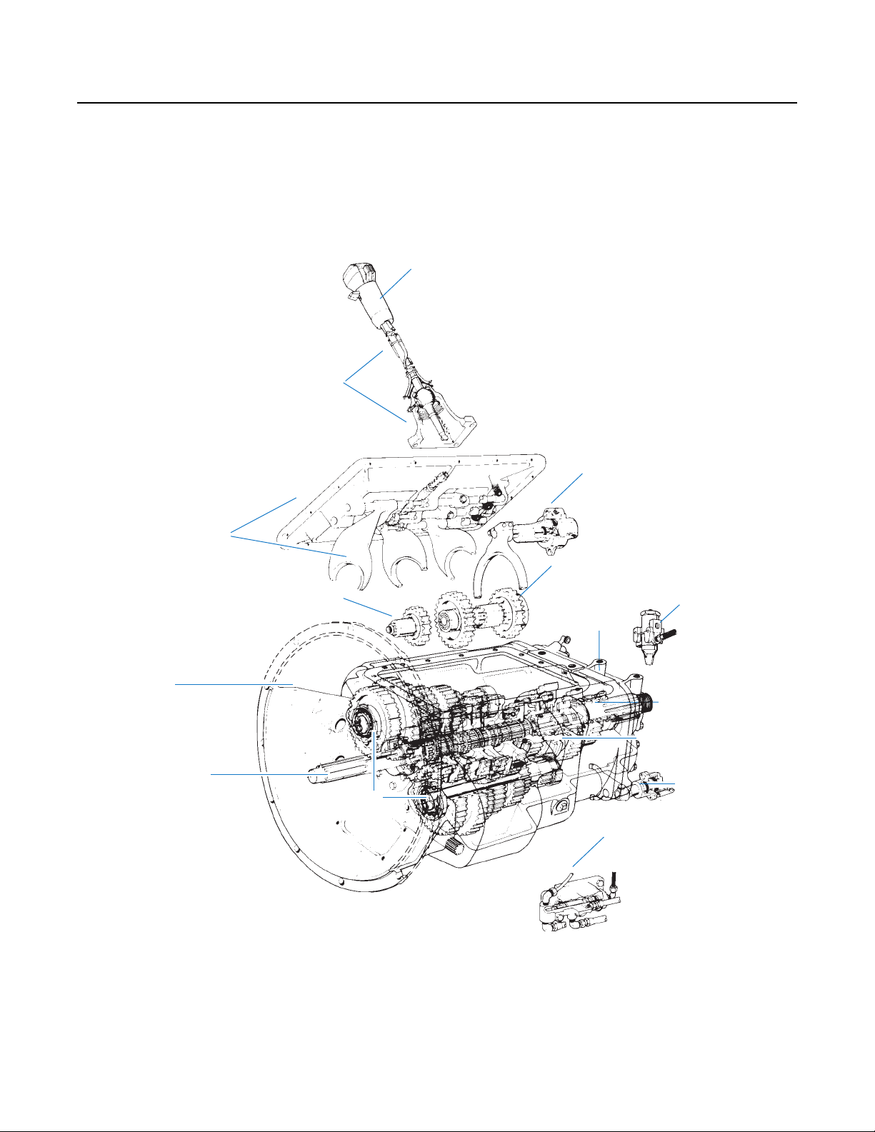
Air System:
Roadranger® Valve
Auxiliary Section:
Range Cylinder
Air System:
Air Filter/Regulator
Auxiliary Section:
Auxiliary Countershaft
Auxiliary Section:
Auxiliary Housing
Air System:
Slave Valve
Front Section:
Countershafts
Front Section:
Mainshaft
Front Section:
Input Shaft / Drive Gear
Front Section:
Clutch Housing / Case Assembly
Front Section:
Reverse Idler
Shift Bar Housing:
Shiftbar Housing Assembly
106004-8-94 15 spd trans
Auxiliary Section:
Reduction Cylinder
Auxiliary Section:
Auxiliary Drive Gear
Shift Bar Housing:
Levers/Housings
& Isolators
Shift Bar Housing:
Shiftbar Housing Assembly
Shift Bar Housing:
Levers/Housings
& Isolators
Transmission Overview
ii

Table of Contents
General Information
Warnings and Cautions ................................................ i
Transmission Overview ............................................... ii
Purpose and Scope of Manual .................................... 1
Serial Tag Information and Model Nomenclature ........ 5
Lubrication Specifications ........................................... 7
Tool Specifications ...................................................... 9
Transmission Torque Specifications ......................... 12
Preventive Maintenance Inspection ........................... 13
Power Flow Diagrams ............................................... 17
Air System Overview ................................................. 36
General Troubleshooting Chart ................................. 42
Air System Troubleshooting ...................................... 44
Timing Procedures .................................................... 57
In-Vehicle Service Procedures
How to Remove Oil Filter Adapter ............................. 61
How to Assemble Oil Filter Adapter ........................... 62
How to Disassemble Roadranger Valve A-5010 ........ 63
How to Assemble Roadranger Valve A-5010 ............. 65
How to Disassemble Roadranger Valve A-4900 ........ 67
How to Assemble Roadranger Valve A-4900 ............. 69
How to Remove the Air Lines and Hoses .................. 71
How to Install the Air Lines and Hoses ...................... 73
How to Remove Compression Type Fittings .............. 75
How to Install Compression Type Fittings ................. 76
How to Remove Push-to-Connect Type Fittings ........ 77
How to Install Push-to-Connect Type Fittings ........... 78
How to Remove Rubber 1/4" Air Hoses ..................... 79
How to Install Rubber 1/4" Air Hoses ........................ 80
How to Remove the Air Filter/Regulator .................... 81
How to Install the Air Filter/Regulator ....................... 82
How to Remove a Roadranger Valve ......................... 83
How to Install a Roadranger Valve ............................ 84
How to Remove a Slave Valve ................................... 85
How to Install a Slave Valve ......................................86
How to Remove the Top-2 Valve Assembly
(Transmissions with Top-2 Option Only) .................. 87
In-Vehicle Service Procedures (cont’d)
How to Install the Top-2 Valve Assembly
(Transmissions with Top-2 Option Only) ...................88
How to Remove the Gear Shift Lever/Remote
Shift Control ..............................................................89
How to Install the Gear Shift Lever/Remote
Shift Control ..............................................................90
How to Adjust the Remote Shift Control (LRC Type) .91
Neutral Switch Operation and Testing ........................93
How to Remove the Neutral Switch ...........................94
How to Install the Neutral Switch ...............................95
Reverse Switch Operation and Testing ......................96
How to Remove the Reverse Switch ..........................97
How to Install the Reverse Switch .............................98
How to Remove the Shift Bar Housing ......................99
How to Install the Shift Bar Housing ........................101
How to Remove the Oil Seal - Mechanical
Speedometer ...........................................................103
How to Install the Oil Seal - Mechanical
Speedometer ...........................................................105
How to Remove the Oil Seal - Magnetic
Speedometer ...........................................................106
How to Install the Oil Seal - Magnetic Speedometer 108
How to Remove the Output Yoke/Companion
Flange and Nut .........................................................110
How to Install the Output Yoke/Companion Flange
and Nut ....................................................................111
How to Remove the Output Yoke / Flange and
Retaining Cap Screws ..............................................112
How to Install the Output Yoke / Flange and
Retaining Cap Screws ..............................................113
How to Remove the Auxiliary Section in Chassis .....114
How to Install the Auxiliary Section in Chassis ........116
How to Remove the Splitter Cylinder Assembly .......119
How to Install Splitter Cylinder Assembly ................121
How to Disassemble the Range Cylinder Assembly
- 7 Series .................................................................124
How to Disassemble the Range Cylinder Assembly
- 9 Series .................................................................125
How to Assemble the Range Cylinder Assembly ......127
iii

Table of Contents
Transmission Overhaul Procedures-Bench Service
How to Disassemble the Gear Shift Lever ............... 130
How to Assemble the Gear Shift Lever .................... 132
How to Remove the Shift Bar Housing .................... 134
How to Install the Shift Bar Housing ....................... 136
How to Disassemble the Standard Shift Bar
Housing ...................................................................138
How to Assemble the Standard Shift Bar Housing ..141
How to Assemble the Forward Shift Bar Housing .... 144
How to Disassemble the Forward Shift Bar Housing 147
How to Remove the Input Shaft Assembly
(without Main Case disassembly) ........................... 150
How to Install the Input Shaft Assembly
(without Main Case disassembly) ........................... 152
How to Remove the Auxiliary Section with
Tapered Bearings .................................................... 154
How to Remove the Splitter Cylinder Assembly ...... 156
How to Remove the Auxiliary Countershaft
Assembly ................................................................ 158
How to Remove the Splitter Gear ............................ 161
How to Disassemble the Range Cylinder Assembly 162
How to Disassemble the Output Shaft Assembly ....164
How to Disassemble the Synchronizer Assembly .... 167
How to Assemble the Synchronizer Assembly ........168
How to Assemble the Output Shaft Assembly ......... 170
How to Install the Splitter Gear ............................... 172
How to Assemble the Range Cylinder Assembly ..... 173
How to Install Splitter Cylinder Assembly ............... 176
How to Install the Auxiliary Countershaft Assembly 179
How to Disassemble the Splitter Gear Bearing
Assembly ................................................................ 182
How to Assemble the Splitter Gear Bearing
Assembly ................................................................ 183
How to Remove the Auxiliary Drive Gear Assembly 184
How to Remove the Clutch Housing
(with Internal Oil Tube) ...........................................186
How to Disassemble the Upper Reverse Idler
Gear Assembly ........................................................ 189
How to Disassemble the Lower Reverse Idler
Gear Assembly ........................................................ 191
How to Remove the Upper and Lower
Countershaft Bearings ............................................. 192
How to Remove the Mainshaft Assembly ................ 194
How to Remove the Countershaft Assemblies ........ 195
How to Disassemble the Countershaft Assemblies ..197
How to Remove the Input Shaft and
Main Drive Gear .......................................................199
How to Disassemble the Mainshaft Assembly .........202
How to Disassemble the Mainshaft Assembly
with
Low Force Gearing .
How to Assemble the Mainshaft Assembly
with Selective (Adjustable) Thickness
Tolerance Washers ..................................................206
How to Assemble the Mainshaft Assembly with
Non-Selective (Non-Adjustable) Tolerance Washers 212
How to Assemble the Mainshaft Assembly with
Low Force Gearing ...................................................215
How to Prepare the Main Case for Assembly ...........218
How to Assemble the Countershaft Assemblies .......219
How to Assemble the Lower Reverse Idler Gear
Assembly .................................................................221
How to Install Countershaft Assemblies ..................225
How to Remove the Integral Oil Pump .....................226
How to Install the Lower Countershaft Bearings ......228
How to Install the Input Shaft and Main Drive Gear 230
How to Install the Mainshaft Assembly ....................232
How to Install the Upper Countershaft Bearings ......234
How to Assemble the Upper Reverse Idler
Gear Assembly .........................................................237
How to Install the Auxiliary Drive Gear Assembly ....240
How to Install the Clutch Housing
(with Internal Oil Tube) ............................................241
How to Disassemble the Integral Oil Pump without
Auxiliary Oil Tube .....................................................244
How to Assemble the Integral Oil Pump without
Auxiliary Oil Tube .....................................................247
How to Install the Integral Oil Pump ........................250
How to Disassemble the Integral Oil Pump with
Auxiliary Oil Tube .....................................................252
How to Assemble the Integral Oil Pump with
Auxiliary Oil Tube .....................................................256
How to Install the Auxiliary Section .........................260
Shim Procedure without a Shim Tool for
Tapered Bearings .....................................................262
How to Remove the Boosted or Hydraulic Actuator
and Adapter Housing ...............................................266
How to Install the Boosted or Hydraulic Actuator
and Adapter Housing ...............................................268
..........................................204
iv

Introduction
General Information
Purpose and Scope of Manual
This manual is designed to provide information necessary to service and repair the Fuller® Transmissions listed on the front.
How to use this Manual
The service procedures have been divided into two sections: In-Vehicle Service Procedures and Transmission Overhaul
Procedures—Bench Service. In-Vehicle Service Procedures contain procedures that can be performed while the Transmission is
still installed in the vehicle. Transmission Overhaul Procedures contain procedures that are performed after the Transmission has
been removed from the vehicle.
The procedure sections are laid out with a general heading at the top outside edge of each page followed by more specific headings
and the procedures. To find the information you need in these sections, first go to the section that contains the procedure you
need. Then look at the heading at the top and outside edge of each page until you find the one that contains the procedure you need.
Transmission Overhaul Procedures follow the general steps for complete disassembly and then assembly of the Transmission.
Note: In some instances the Transmission appearance may be different from the illustrations, but the procedure is the same.
Disassemble Precautions
It is assumed in the detailed assembly instructions that the lubricant has been drained from the Transmission, the necessary
linkage and vehicle Air Lines disconnected and the Transmission has been removed from vehicle Chassis. Removal of the Gear
Shift Lever Housing Assembly (or Remote Control Assembly) is included in the detailed instructions (How to Remove the Gear
Shift Lever). This Assembly MUST be detached from the Shift Bar Housing before the Transmission can be removed.
Follow closely each procedure in the detailed instructions, make use of the text, illustrations, and photographs provided.
Assemblies
• When disassembling the various Assemblies, such as the Mainshaft, Countershafts, and Shift Bar Housing, lay all parts
on a clean bench in the same sequence as removed. This procedure will simplify assembly and reduce the possibility of
losing parts.
Bearings
• Carefully wash and lubricate all usable bearings as removed and protectively wrap until ready for use. Remove bearings
planned to be reused with pullers designed for this purpose.
Cleanliness
• Provide a clean place to work. It is important that no dirt or foreign material enters the unit during repairs. Dirt is an
abrasive and can damage bearings. It is always a good practice to clean the outside of the unit before starting the
planned disassembly.
Input Shaft
• The Input Shaft can be removed from the Transmission without removing the Countershafts, Mainshaft, or Main Drive
Gear. Special procedures are required and provided in this manual.
1

Introduction
Snap Rings
• Remove Snap Rings with pliers designed for this purpose. Snap rings removed in this manner can be reused, if they
are not sprung or loose.
When Using Tools to Move Parts
• Always apply force to Shafts, Housings, etc., with restraint. Movement of some parts is restricted. Never apply force
to driven parts after they stop solidly. The use of soft Hammers, Soft Bars, and Mauls for all disassembly work is
recommended.
Inspection Precautions
Before assembling the Transmission, check each part carefully for abnormal or excessive wear and damage to determine reuse or
replacement. When replacement is necessary, use only genuine Fuller
extended life from your unit.
Since the cost of a new part is generally a small fraction of the total cost of downtime and labor, avoid reusing a questionable part
which could lead to additional repairs and expense soon after assembly. To aid in determining the reuse or replacement of any
Transmission part, consideration should also be given to the unit's history, mileage, application, etc.
Recommended inspection procedures are provided in the following checklist:
Bearings
• Wash all Bearings in clean solvent. Check Balls, Rollers, and Raceways for pitting, discoloration, and spalled areas.
Replace Bearings that are pitted, discolored, spalled, or damaged during disassembly.
• Lubricate Bearings that are not pitted, discolored, or spalled and check for axial and radial clearances.
• Replace bearings with excessive clearances.
• Check bearing fit. Bearing Inner Races should be tight to Shaft; Outer Races slightly tight to slightly loose in Case Bore.
If the Bearing spins freely in the Bore the Case should be replaced.
Bearing Covers
• Check Covers for wear from thrust of adjacent Bearing. Replace Covers damaged from thrust of Bearing Outer Race.
• Check Cover Bores for wear. Replace those worn or oversized.
Clutch Release Parts
®
Transmission parts to assure continued performance and
• Check Clutch Release parts. Replace Yokes worn at Cam surfaces and Bearing Carrier worn at Contact Pads.
• Check Pedal Shafts. Replace those worn at Bushing surfaces.
Gears
• Check gear teeth for frosting and pitting. Frosting of gear teeth faces presents no threat of Transmission failure. Often in
continued operation of the unit, frosted gears "heal" and do not progress to the pitting stage. In most cases, gears with
light to moderate pitted teeth have considerable gear life remaining and can be reused, but gears in the advanced stage
of pitting should be replaced.
• Check for gears with Clutching teeth abnormally worn, tapered, or reduced in length from clashing during shifting.
Replace gears found in any of these conditions.
• Check Axial Clearance of gears.
2

Introduction
General Information
Gear Shift Lever Housing Assembly
• Check spring tension on Shift Lever. Replace Tension Spring if lever moves too freely.
• If Housing is disassembled, check Gear Shift Lever bottom end and Shift Finger Assembly for wear. Replace both gears
if excessively worn.
Gray Iron Parts
• Check all gray iron parts for cracks and breaks. Replace parts found to be damaged.
Oil Return Threads and Seals
• Check oil return threads on the Input Shaft. If return action of threads has been destroyed, replace the Input Shaft.
• Check Oil Seal in Rear Bearing Cover. If sealing action of lip has been destroyed, replace Seal.
O-Rings
• Check all O-Rings for cracks or distortion. Replace if worn.
Reverse Idler Gear Assemblies
• Check for excessive wear from action of Roller Bearings.
Shift Bar Housing Assembly
• Check for wear on Shift Yokes and Block at pads and lever slot. Replace excessively worn parts.
• Check Yokes for correct alignment. Replace sprung Yokes.
• Check lock screw in Yoke and Blocks. Tighten and rewire those found loose.
• If Housing has been disassembled, check Neutral Notches of Shift Bars for wear from Interlock Balls.
Sliding Clutches
• Check all Shift Yokes and Yoke slots in Sliding Clutches for extreme wear or discoloration from heat.
• Check engaging teeth of Sliding Clutches for partial engagement pattern.
Splines
• Check Splines on all shafts for abnormal wear. If Sliding Clutch gears, Companion Flange, or Clutch Hub has wear
marks in the Spline sides, replace the specific shaft effected.
Synchronizer Assembly
• Check Synchronizer for burrs, uneven and excessive wear at contact surface, and metal particles.
• Check Blocker Pins for excessive wear or looseness.
• Check Synchronizer contact surfaces on the Synchronizer cups for wear.
Washers
• Check surfaces of all washers. Washers scored or reduced in thickness should be replaced.
3

Introduction
IMPORTANT
Assembly Precautions
Make sure that Case interiors and Housings are clean. It is important that dirt and other foreign materials are kept out of the
Transmission during assembly. Dirt is an abrasive and can damage polished surfaces of Bearings and Washers. Use certain
precautions, as listed below, during assembly.
Axial Clearances
• Maintain original Axial Clearances of 0.006–0.015 in. for Mainshaft Gears.
Bearings
• Use a Flange-End Bearing Driver for bearing installation. These special drivers apply equal force to both Bearing Races,
preventing damage to Balls/Rollers and Races while maintaining correct Bearing alignment with Bore and Shaft. Avoid
using a Tubular or Sleeve-Type Driver, whenever possible, as force is applied to only one of the Bearing Races.
Cap Screws
®
• To prevent oil leakage and loosening, use Fuller
Gaskets
• Use new Gaskets throughout the Transmission as it is being rebuilt. Make sure all Gaskets are installed. An omission of
any Gasket can result in oil leakage or misalignment of Bearing Covers.
Sealant #71205 on all Cap Screws.
Initial Lubrication
• Coat all Limit Washers and Shaft Splines with Lubricant during assembly to prevent scoring and galling of such parts.
O-Rings
• Lubricate all O-Rings with silicon lubricant.
Universal Joint Companion Flange or Yoke
• Pull the Companion Flange or Yoke tightly into place with the Output Shaft Nut, using 650–700 lb-ft (881.28–949.07
N•m) of torque. Make sure the Speedometer Drive Gear or a Replacement Spacer of the same width has been installed.
Failure to pull the Companion Flange or Yoke tightly into place can result in damage to the Mainshaft Rear Bearing.
See the appropriate Illustrated Parts Lists (specified by model series) to ensure that proper parts are used during assembly of
the Transmission.
4
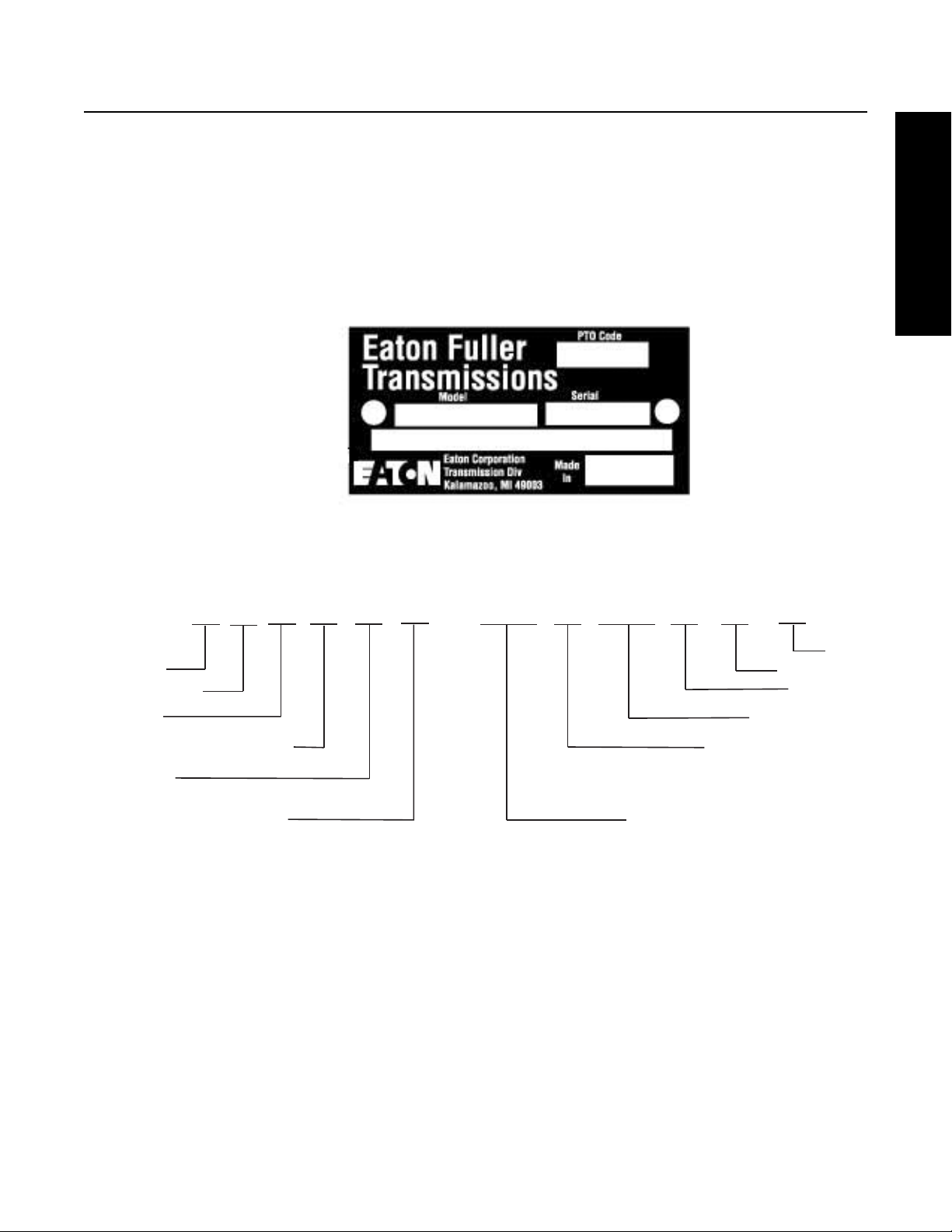
Model Designations
General Information
Roadranger
Twin Countershaft
Low-Inertia
F= Forward Opening Shift Housing
Ratio Set
Forward Speeds
6= Multi-Mesh Gearing
7= Helical Auxiliary Gearing and
Multi-Mesh Front Section Gearing
9= Improved Seal System
This (x) 100 = Nominal Torque Capacity
C= Convertible
R
TL
C
F
1 6 7 1 8
A
or
O
O= Overdrive w/ Direct Shift Pattern
T2
MT
or
Top 2
Multi-Torque
______
____
Serial Tag Information and Model Nomenclature
Transmission model designation and other Transmission identification information are stamped on the Transmission Tag.
To identify the Transmission model designation and Serial Number, locate the Tag on the Transmission and then locate the
numbers as shown.
When calling for service assistance or parts, have the Model and Serial Numbers handy.
Do not remove or destroy the Transmission Identification Tag.
The Model Number gives basic information about the Transmission. Use this number when calling for service assistance or
replacement parts.
Serial Number
The Serial Number is the sequential identification number of the Transmission. Before calling for service assistance, write the
number down. It may be needed.
Bill of Material or Customer Number
This number may be located below the Model and Serial Numbers. It is a reference number used by Eaton.
5
Model Designations
Model Options
Torque Rating
The torque rating of the Transmission specified in the Model Number is the Input Torque Capacity in lb-ft. Various torque ratings
are available. For more information, call your Eaton Regional Sales and Service Office at 1-800-826-HELP (4357).
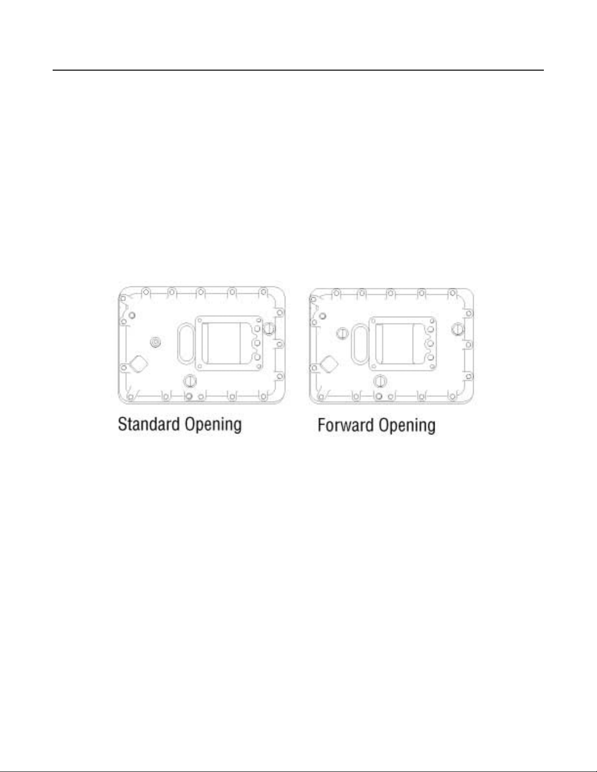
Shift Bar Housings
Two types of Shift Bar Housings are available for this Transmission. Both are described and shown below.
Standard
The standard Shift Bar Housing has a Gear Shift Lever opening that is located toward the rear of the Transmission.
Forward
The forward Shift Bar Housing has a Gear Shift Lever opening located three inches closer to the Transmission front than the
standard opening. This forward design allows greater flexibility in mounting the Transmission and is indicated by an “F” in
the Model Number.
Lubrication Pumps
Three types of Lubrication Pumps are available for use on this Transmission and are described below:
Internal: An internal Lubrication Pump is located in the lower front of the Transmission and is driven off the Upper Countershaft.
13-Speed Transmissions rated 1550 lb-ft and above include the Internal Pump standard. All 18-Speed Transmissions contain the
Internal Lube Pump.
Auxiliary Countershaft: An Auxiliary Countershaft Pump is mounted on the rear of the Transmission and driven off the Auxiliary
Countershaft.
PTO Driven: A PTO driven pump is externally mounted on the 6 or 8 bolt PTO openings and driven off the PTO Gear.
Power Take Off (PTO) Usage
PTOs can be mounted in the following way:
6 or 8 Bolt: The 6 or 8 bolt openings are standard with the Transmission. The PTO is mounted to the opening and driven from
the PTO Gear on the Front Countershaft.
Thru-Shaft: The Thru-Shaft PTO mounts on the rear of the Transmission. It requires a special Auxiliary Housing and Main Case
Countershaft with Internal Splines.
6

Lubrication
General Information
IMPORTANT
Lubrication Specifications
Transmission Filters should be changed during regular lube intervals. Inspection of the Transmission Filter should be
conducted during preventive maintenance checks for damage or corrosion. Replace as necessary.
• For a list of Eaton
• The use of lubricants not meeting these requirements will affect warranty coverage.
• Additives and friction modifiers must not be introduced. Never mix engine oils and gear oils in the same Transmission.
Transmission Operating Angles
If the Transmission operating angle is more than 12 degrees, improper lubrication will occur. The operating angle is the
Transmission mounting angle in the Chassis plus the percent of upgrade (expressed in degrees). For operating angles over
12 degrees, the Transmission must be equipped with an Oil Pump or Cooler kit to insure proper lubrication.
Operating Temperatures with Oil Coolers
The Transmission must not be operated consistently at temperatures above 250 °F. Operation at temperatures above 250 °F
[121 °C] causes loaded gear tooth temperatures to exceed 350 °F [177 °C] which will ultimately destroy the heat treatment of
the gears. If the elevated temperature is associated with an unusual operating condition that will reoccur, a Cooler should be
added, or the capacity of the existing cooling system increased.
®
Approved Synthetic Lubricants, see TCMT0021 or call 1-800-826-HELP (4357).
The following conditions in any combination can cause operating temperatures of over 250 °F [121 °C]:
• Operating consistently at slow speed.
• High ambient temperatures.
• Restricted air flow around Transmission.
• Use of engine retarder.
• High horsepower operation.
Note: Transmission Coolers must be used to reduce the operating temperatures when the above conditions are encountered.
7

Lubrication
Oil Cooler Chart
Table 4
Transmission Oil Coolers are:
Recommended
• With engines of 350 H.P. and above.
Required
• With engines 399 H.P. and above and GCW’s over 90,000 lbs.
• With engines 399 H.P. and above and 1400 lb-ft (1898.15 N•m) or greater torque.
• With engines 1500 lb-ft (2033.73 N•m) and above
18-speed AutoShift Transmissions require use of an Eaton® supplied Oil-to-Water Cooler or approved equivalent.
• With engines 450 H.P. and above.
8

Recommended Tools
General Information
Tool Specifications
Some repair procedures pictured in this Manual show the use of specialized tools. Their actual use is recommended as they make
Transmission repair easier, faster, and prevent costly damage to critical parts.
For the most part, ordinary Mechanic's Tools such as Socket Wrenches, Screwdrivers, etc., and other standard shop items such
as a Press, Mauls and Soft Bars are the only tools needed to successfully disassemble and reassemble any Fuller
The following tables list and describe the typical tools required to properly service this model Transmission above and beyond the
necessary basic Wrenches, Sockets, Screwdrivers, and Pry Bars.
®
Transmission.
General Tools
The following tools are available from several Tool Manufacturers such as Snap-On, Mac, Craftsman, OTC, and many others:
Tool Purpose
0–100 lb-ft 1/2" drive Torque Wrench
0–700 lb-ft 3/4" or 1" drive Torque Wrench Torquing of Output Nut to 650–700 lb-ft (881.28–949.07 N•m)
0–50 lb-in 3/8" drive Torque Wrench General torquing of fasteners
0–30 lb-in 1/4" drive Torque Wrench
70 MM or 2 2/4" Socket - Standard Depth To remove the Output Shaft Nut
Snap Ring Pliers - Large Standard External
General torquing of fasteners (Typically 15–80 lb-ft
[20.34–108.47 N•m])
Torquing of Cap Screws to 7 lb-in (0.79 N•m) during Auxiliary Countershaft
Bearing endplay setting procedure
To remove the Snap Rings at the Auxiliary Drive Gear, Input Shaft Bearing,
and Countershaft Bearings
Feeler Gauges To set Mainshaft Washer Endplay and Auxiliary Tapered Bearing Endplay
Rolling Head Pry Bar To remove the Auxiliary Drive Gear Bearing
(2) Air Pressure Gauges 0–100 PSI (0–1034 kPa) To troubleshoot and verify correct operation of Air System
Universal Bushing Driver
To remove and install Clutch Housing Bushings. Bushing
OD = 1.125 in., ID = 1.000 in.
9

Recommended Tools
Special Tools
The following Transmission Tools are available directly from K-Line Industries. To obtain any of these tools listed, contact K-Line
by phone or visiting the online store.
K-Line Industries, Inc.
315 Garden Avenue
Holland, MI 49424
1-800-824-KLINE (5546)
http://www.klineind.com/
K-Line Part # Tool Tool Description
RR1001TR-1 Driver - Output Seal Slinger
RR1001TR-2 Driver - Output Seal
RR1001TR-4 Driver - Output Seal Slinger
RR1001TR-8 Driver - Output Seal
RR1002TR Auxiliary Countershaft Support Straps
RR1004TR Mainshaft Lifting Hook
RR1005TR Driver - Input Bearing
RR1006TR Auxiliary Section Lifting Bracket Used to lift Transmission Auxiliary Sections.
RR1007TR
RR1010TR Slide Hammer Used to remove Bearing Races, Reverse Idler Shafts, and Seals.
RR1011TR-1 Slide Hammer Attachment Used for removing Output Seals.
Shimming Gauge - Auxiliary
Countershaft (0.100")
Used to install Output Seal Protective Slinger on FR & RT-Series
(Gen 9) Transmission Output Yokes.
Used to install Output Seal in Rear Bearing Cover on RT-Series
(Gen 6 & 7) Transmissions with 2.75" Output Shaft.
Used to install Output Seal Protective Slinger on RT-Series (Gen 6 &
7) Transmission Output Yokes.
Used with Seal Driver RR1001TR-2 to install Output Seal in Rear
Bearing Cover on FR & RT-Series (Gen 9) Transmissions.
Used to support the aux-Countershaft Assemblies when servicing the
aux-section on FR & RT-Series (Gen 7 & 9) Transmissions.
Used to remove/install Mainshaft Assembly into the Transmission
Main Case.
Used to install the Input Bearing on Transmissions with 2" & 1.75"
Input Shafts.
Used for setting proper Auxiliary Countershaft Bearing clearance on
FR-Series and RT-Series (Gen 7 & 9) Transmissions.
RR1011TR-2 Slide Hammer Attachment Used for removing Bearing Races from the Transmission Case.
RR1011TR-3 Slide Hammer attachment Used for removing Bearing Races from the Transmission Case.
RR1012TR-2 Driver - Countershaft Front Bearings
RR1012TR-3 Puller - Countershaft Front Bearings
RR1012TR-4 Driver - Countershaft Rear Bearings Used to install Rear Countershaft Bearings, RT-Series Transmissions.
RR1012TR-5
RR1012TR-6
RR1013TR Timing Block - RT-Series Countershaft
10
Driver - Auxiliary Countershaft
Bearings
Driver - Auxiliary Countershaft
Bearings
Used to install Front Countershaft Bearings on RT-Series
Transmissions.
Used to remove Front Countershaft Bearings on RT-Series
Transmissions.
Used to install Auxiliary Countershaft Bearings on FR & RT-Series
Transmissions with Auxiliary Section helical gearing.
Used to install Auxiliary Countershaft Bearings on RT-Series
Transmissions with Auxiliary Section spur gearing.
Used to support the Upper Countershaft during Main Box assembly on
RT-Series Transmissions.
Recommended Tools
General Information
K-Line Part # Tool Tool Description
RR1015TR
RR1017TR Pusher - Countershaft
RR1019TR Hand Maul Used with Bearing and Seal Drivers for part installation/removal.
RR1020TR Soft Bar Used with hand Maul to remove parts from the Transmission.
RR1022TR Countershaft Support Tool
RR1023TR Puller - Input Bearing Used to remove the Input Bearing on FR & RT-Series Transmissions.
RR1024TR Driver - Output Bearing Used to install the Output Bearing on FR & RT-Series Transmissions.
Driver - Countershaft Front/Rear
bearings
Used to install Front and Rear Countershaft Bearings on FR-Series
Transmissions.
Used to push the Countershaft Assembly rearward to create clearance
for Bearing Puller on FR & RT-Series Transmissions.
Used to support the Upper Countershaft during Main Box disassembly
on FR & RT-Series Transmissions.
Shop Equipment
Tool Purpose
20 Ton capacity Press To press Countershaft Gears from Countershaft.
Eaton Aftermarket Parts
The following tools are available through Eaton Aftermarket Parts. To obtain any of the tools listed, contact your local Eaton
Parts Distributor.
Tool Purpose Eaton Part Number
5/32" Air Line Release Tool
Air Line Cutting Tool
To remove 5/32" Air Lines from Push-toConnect Fittings.
To cut plastic Air Lines smoothly and
squarely.
P/N 4301157 included in Kit K-2394
P/N 4301158 included in Kit K-2394.
11
Recommended Tools
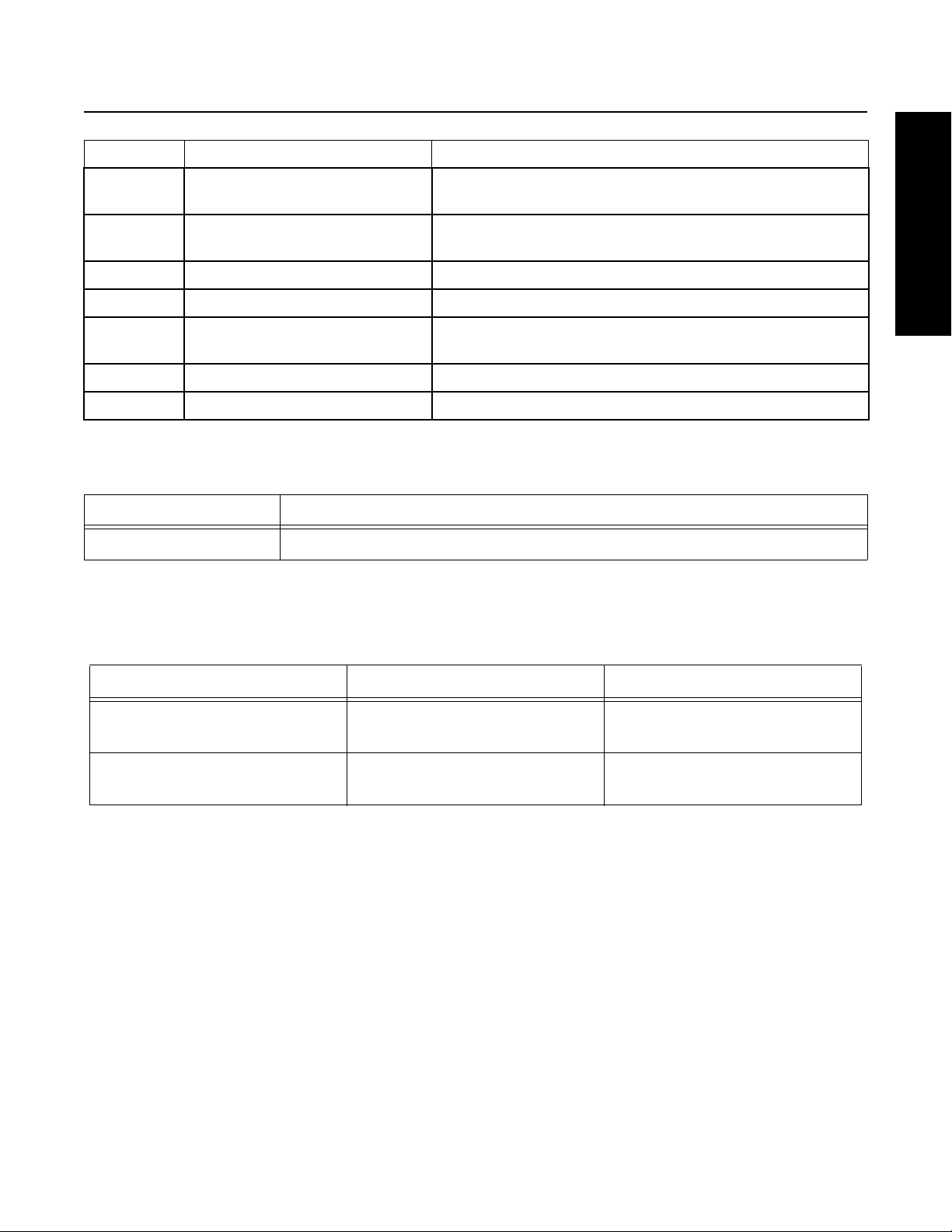
(1) Oil Drain Plug
45-55 lb-ft (61.01-74.57 Nm)
¾ Pipe Threads
(2) Support Stud Nuts
170-185 lb-ft (230.49-250.93 Nm)
5
/8 -18 Threads, Use Lockwashers
(1) Output Nut
650-700 lb-ft (881-949 Nm)
Intall output nut onto a clean, oil free shaft.
Note: DO NOT reuse output nut, replace
with new if removed from shaft.
(1) Oil Fill Plug
35-50 lb-ft (47-68 Nm)
1¼ Pipe Threads
Transmission Torque Specifications
Correct torque application is extremely important to assure long Transmission life and dependable performance. Over-tightening
or under-tightening can result in a loose installation and in many instances, eventually cause damage to Transmission Gears,
Shafts, and/or Bearings. Use a Torque Wrench whenever possible to attain recommended lb-ft ratings. Do not torque Cap
Screws dry.
12

Preventive Maintenance
General Information
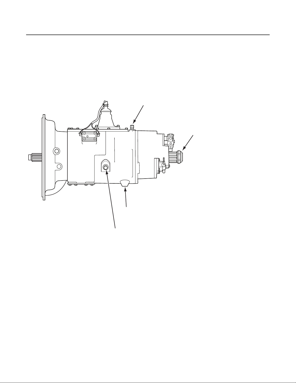
Preventive Maintenance Inspection
Everyday there are countless vehicles operating over the highways with Transmissions in such a neglected mechanical condition,
they can be referred to as failures looking for a place to break down. They lack a proper and organized preventive
maintenance program.
Preventive maintenance is a general term which applies to all procedures necessary to have maximum life and satisfactory service
at the lowest possible cost, short of removing and repairing the unit.
A number of conditions contrary to good preventive maintenance can generally be pointed to when inspecting a failed
Transmission. Taking a few minutes every so many hours or miles to do a few simple checks could help avoid eventual breakdown
or reduce the repair cost. If the Transmission is not cared for, it will breakdown.
Preventative Maintenance Check Points
Note: Transmission appearance may differ, however the procedure is the same.
13

Preventive Maintenance
1. Air System and Connections
• Check for leaks, worn Air Lines, loose connections and Cap Screws.
2. Clutch Housing Mounting
• Check all Cap Screws of Clutch Housing flange for looseness.
3. Clutch Release Bearing (Not Shown)
• Remove Hand Hole Cover and check Radial and Axial Clearance in Release Bearing.
• Check relative position of thrust surface of Release Bearing with Thrust Sleeve on Push-type Clutches.
4. Clutch Pedal Shaft and Bores
• Pry upward on Shafts to check wear.
• If excessive movement is found, remove Clutch Release Mechanism and check Bushings on Bores and wear on
Shafts. See OEM literature.
5. Lubricant
• See Lubrication Manual TCMT0021.
6. Oil Filter
• Oil Filter Inspection (during vehicle PM schedule):
- Inspect Oil Filter for damage or rust. Replace as necessary.
- Inspect Oil Filter Adapter for damage or leakage. Replace as necessary.
• Oil Filter Replacement
- Replace every 100,000 miles and top off fluid.
- Every Transmission fluid change.
7. Filler and Drain Plugs
• Remove Filler Plugs and check level of lubricant at specified intervals. Tighten fill and Drain Plugs securely.
8. Cap Screws and Gaskets
• For applicable models, check all Cap Screws, especially those on PTO Covers and Rear Bearing Covers for
looseness which would cause oil leakage.
• Check PTO opening and Rear Bearing Covers for oil leakage due to faulty Gasket.
9. Gear Shift Lever
• Check for looseness and free play in Housing. If Lever is loose in Housing, proceed with Check No. 10.
10. Gear Shift Lever Housing Assembly
• If present, remove Air Lines at Air Valve or Slave Valve. Remove the Gear Shift Lever Housing Assembly from
the Transmission.
• Check the Tension Spring and Washer for set and wear.
• Check the Gear Shift Lever Spade Pin and slot for wear.
• Check bottom end of Gear Shift Lever for wear and check slot of Yokes and Blocks in Shift Bar Housing for wear
at contact points with Shift Lever.
Checks With Drive Line Dropped
11. Universal Joint Companion Flange or Shaft Nut
• Check for tightness. Tighten to recommended torque.
12. Output Shaft (Not Shown)
• Pry upward against Output Shaft to check radial clearance in Mainshaft Rear Bearing.
14

Preventive Maintenance
General Information
Checks With Universal Joint Companion Flange or Yoke Removed
Note: If necessary, use solvent and shop rag to clean sealing surface of Companion Flange or Yoke. Do not use Crocus Cloth,
Emery Paper, or other abrasive materials that will mar surface finish.
13. Splines on Output Shaft (Not Shown)
• Check for wear from movement and chucking action of the Universal Joint Companion Flange or Yoke.
14. Mainshaft Rear Bearing Cover (Not Shown)
• Check Oil Seal for wear.
Inspection
Part to Inspect What to Check For Action to be Done
Speedometer Cables should not be
loose.
Speedometer Connections
Rear Bearing Cover Cap
Screws, Gasket, and Nylon
Collar
Output Shaft Nut
PTO Covers and Openings Check the Cap Screws for tightness.
Should be an O-Ring or gasket between
the mating Speedometer Sleeve and the
Rear Bearing Cover.
Check Retaining Cap Screws for
tightness.
Verify Nylon Collar and Gasket are
installed at the chamfered hole, aligned
near the mechanical Speedometer
opening.
Verify that a Rear Bearing Cover gasket
is in place.
Check the Output Shaft Nut for
tightness.
Applied hydraulic Thread Sealant #71208 to threads,
torque Speedometer Sleeve to 35–50 lb-ft
(47.45–67.79 N•m).
Replace the O-Ring/gasket if damaged or missing.
Apply Eaton Sealant #71205 to the Cap Screw
threads, torque to 35–45 lb-ft (47.45–61.01 N•m).
Use new parts if need to replace. Apply Eaton
Sealant #71205 to the Cap Screw threads, torque to
35–45 lb-ft (47.45–61.01 N•m).
Install a new Gasket if Rear Bearing Cover was
removed.
Torque the Output Shaft Nut to 650–700 lb-ft
(881.28–949.07 N•m). Do not over torque the
Output Nut.
Apply Eaton Sealant #71205 to the Cap Screw
threads. Torque 6 bolt PTO Cap Screws to
35–45 lb-ft (47.45–61.01 N•m), 8 bolt PTO Cap
Screws to 50–65 lb-ft (67.79–88.13 N•m).
Gray Iron Parts
Front Bearing Cover
Oil Cooler and Oil Filter
Oil Drain Plug, Oil Fill Plug
Check Front Bearing Cover, Front Case,
Shift Bar Housing, Rear Bearing Cover,
and Clutch Housing for cracks or
breaks.
Check return threads for damage. If threads damaged, replace the Input Shaft.
Check the Cap Screws for tightness.
Check all connectors, Fittings, Hoses,
and Filter Element for tightness.
Check the Oil Drain Plug and the Oil Fill
Plug for leakage.
Replace parts found to be damaged.
Torque the Cap Screws to 35–45 lb-ft
(47.45–61.01 N•m).
Tighten any loose Fittings.
Torque the Oil Drain Plug to 45–55 lb-ft
(61.01–74.57 N•m), Oil Fill Plug to 60–70 lb-ft
(81.35–94.91 N•m).
15
Preventive Maintenance
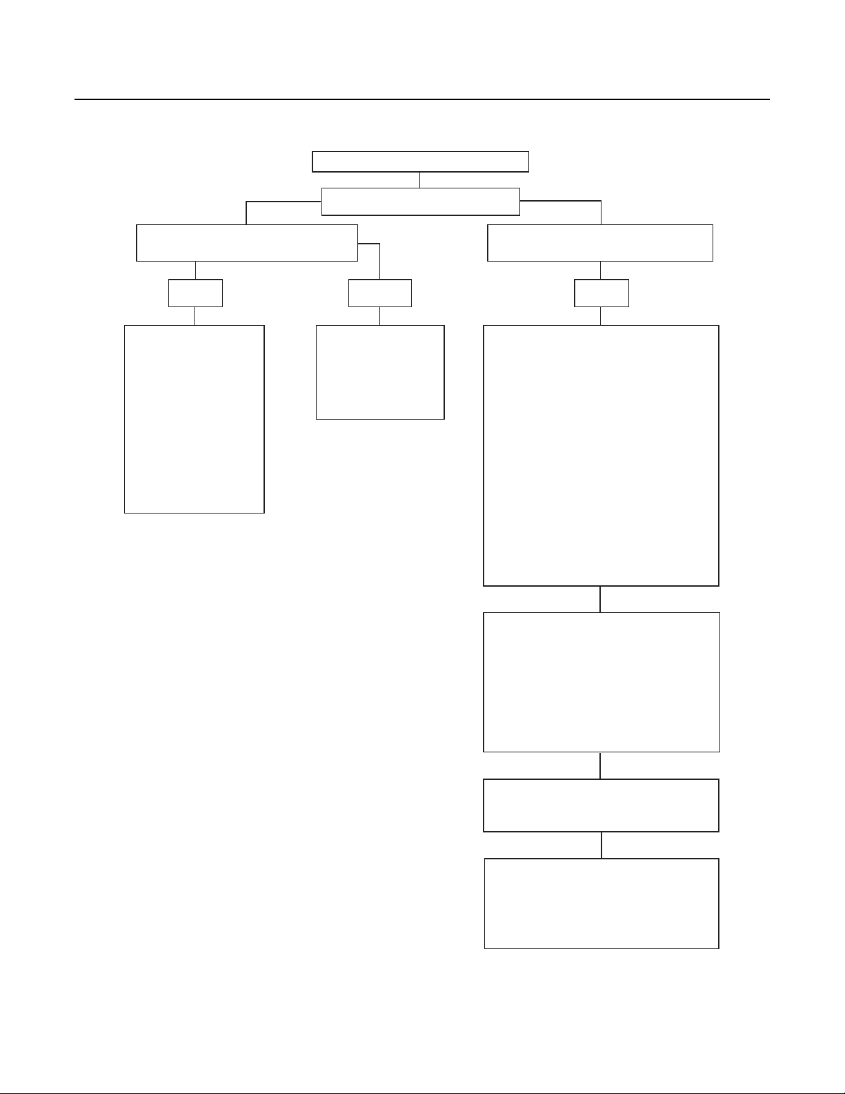
Oil Leak Inspection Process
Inspect for Oil Leak
Determine if it is a Weep or a Leak
Weep: Stained, damp, no drips, light oil film,
dirt adhered to the contaminated area.
Gasket Rear Seal Leak
1. Clean suspected oil weep
area with a clean dry cloth
or mild soluble degreaser.
2. Ensure lube is to proper
level.
3. Notify the customer that it
is only a weep and it is not
considered to be detrimental
to the life of the transmission.
4. Repair is complete.
1. Do not repair: Rear seal is
designed to allow minimal
seepage.
2. Ensure lube is to proper
level.
Leak: Extremely wet or dripping of oil in the
contaminated area.
Step 1
1. Determine the origin of the leak path.
2. If origin of leak is obvious skip to Step 3.
3. If the origin of the oil leak is not obvious then
use either of the two following steps to determine
the oil leak:
Note: Do not use a high pressure spray washer to
clean the area. Use of a high pressure spray may
force contamination into the area of concern and
temporarily disrupt the leak path.
i. Clean area with a clean dry cloth or mild
soluble degreaser and fill the transmission to
the proper lube level.
OR
ii. Clean the area as noted above and insert tracer
dye into the transmission lube and fill
transmission to proper lube level.
Step 2
Operate vehicle to normal transmission operating
temperature and inspect the area for oil leak(s)
visually or if tracer dye was introduced use an UVL
(Ultraviolet Light) to detect the tracer dye’s point of origin.
Note: When inspecting for the origin of the leak(s)
make sure the assumed leak area is not being
contaminated by a source either forward or above
the identified area such as the engine, shift tower,
shift bar housing, top mounted oil cooler, etc...
16
Step 3
Once the origin of the leak is identified, repair the
oil leak using proper repair procedures from the
designated model service manual.
Step 4
After the repair is completed, verify the leak is repaired
and operate the vehicle to normal transmission
operating temperature. Inspect repaired area to ensure
oil leak has been eliminated. If the leak(s) still occurs,
repeat steps or contact the Roadranger Call Center
at 1-800-826-4357.
Power Flow
General Information
12
Power Flow Diagrams
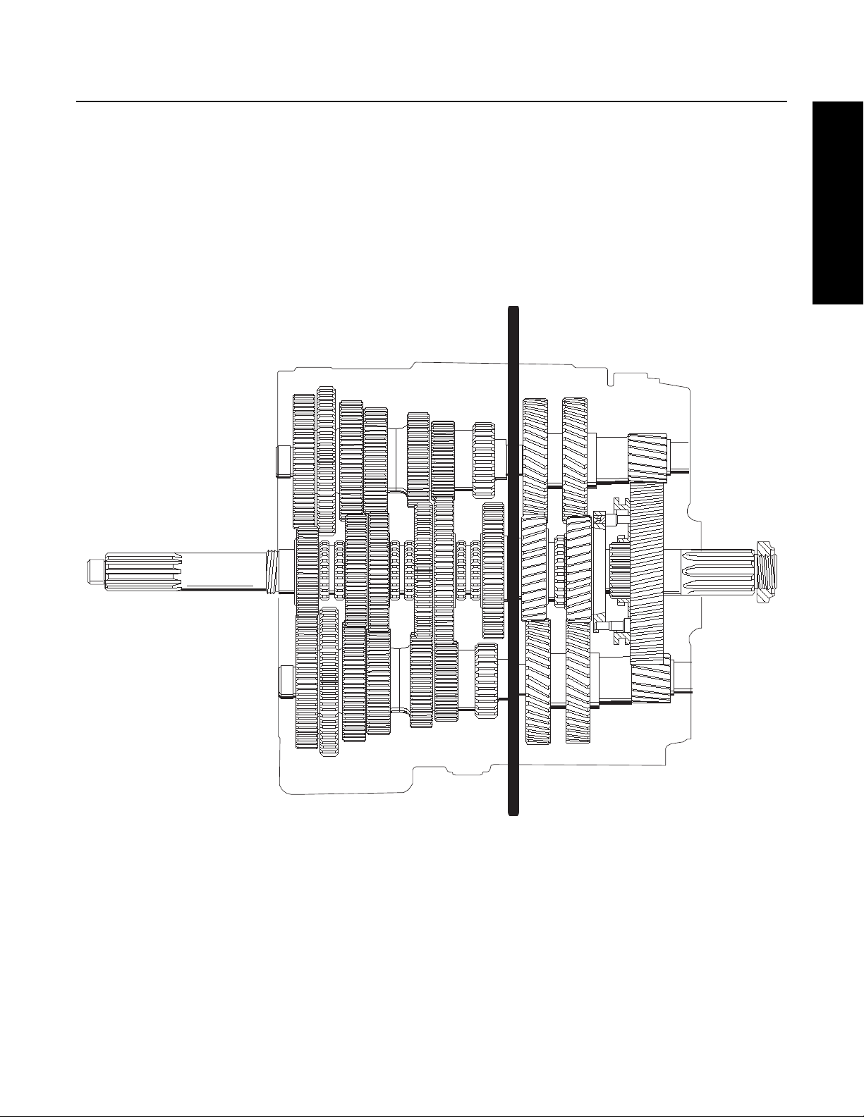
An understanding of the engine's Power Flow through a Transmission in each particular gear will assist the Technician in
troubleshooting and servicing a Transmission.
The Fuller
or Front Section contains six Gear Sets which are shifted with the Gear Shift Lever. The second “Transmission” called the Auxiliary
Section, contains three Gear Sets and is shifted with air pressure.
Note: This Transmission is referred to as a Constant Mesh Type Transmission. When in operation, all gears are turning even
®
Transmission can be thought of as two separate “Transmissions” combined into one unit. The first “Transmission”
though only some of them are transferring power.
Cross Sectional View
1. Front Section
2. Auxiliary Section
17
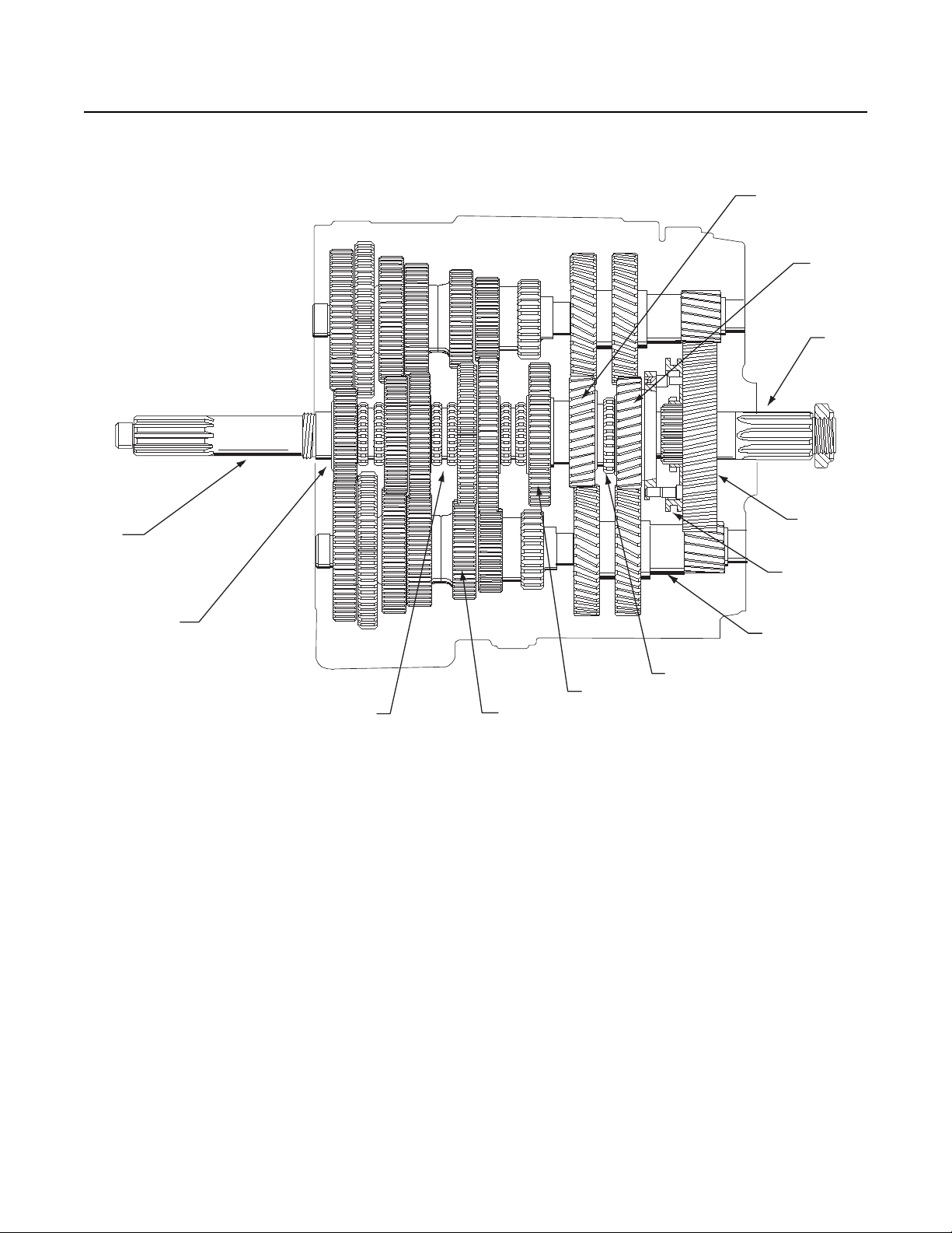
Power Flow
The Transmission components in the figure below shows the Transmission with the main components called out. Note that the
Transmission is in the Neutral position because the Sliding Clutches are all in their center positions and not engaged in any gears.
12
11
10
1
2
34
Transmissions Components
1. Input Shaft
2. Main Drive Gear
3. Sliding Clutch
4. Countershaft
5. Mainshaft Gear
6. Auxiliary Splitter Clutch (slides on Front Section Mainshaft)
9
8
7
6
5
7. Auxiliary Countershaft
8. Range Sliding Clutch
9. Auxiliary Mainshaft Reduction Gear
10. Output Shaft (Auxiliary Mainshaft)
11. Splitter Gear
12. Auxiliary Drive Gear
18
Power Flow
General Information
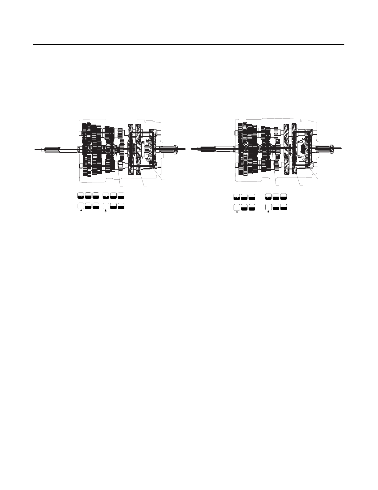
1
2
3
153
7
264
8
Neutral
R
LO
RTO
154
8
263
7
Neutral
R
LO
RTX
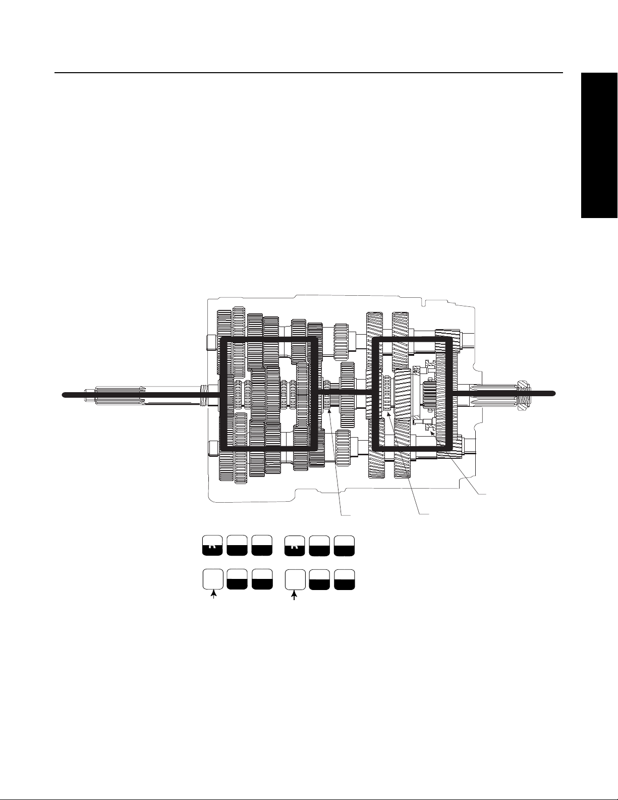
Front Section Power Flow
Note: The heavy lines in the figure below outline the Power Flow description. For help in understanding the Transmission
components, refer to the figure “Transmission Components” on the previous page.
1. Power (torque) from the vehicle's engine is transferred to the Transmission's Input Shaft.
2. The Input Shaft rotates the Main Drive Gear through internal Splines in the hub of the Gear.
3. The Main Drive Gear meshes with both Countershaft driven gears and the torque is split between both Countershafts.
4. Because the Countershaft Gears are in constant mesh with the Mainshaft Gears, all the Front Section gearing rotates.
However, only the engaged or selected Mainshaft Gear will have torque. External Clutching teeth on the Sliding Clutch
will engage internal Clutching teeth on the selected Mainshaft Gear. Torque will now be provided from both opposing
Countershaft Gears, into the engaged Mainshaft Gear, and through the Sliding Clutch to the Front Section Mainshaft.
5. The rear of the Front Section Mainshaft is splined into the Auxiliary Splitter Clutch and torque is now delivered to the
Auxiliary Splitter Clutch.
Front Section Power Flow
1. Sliding Clutch forward
2. Sliding Clutch forward
3. Sliding Clutch rearward
19
Power Flow
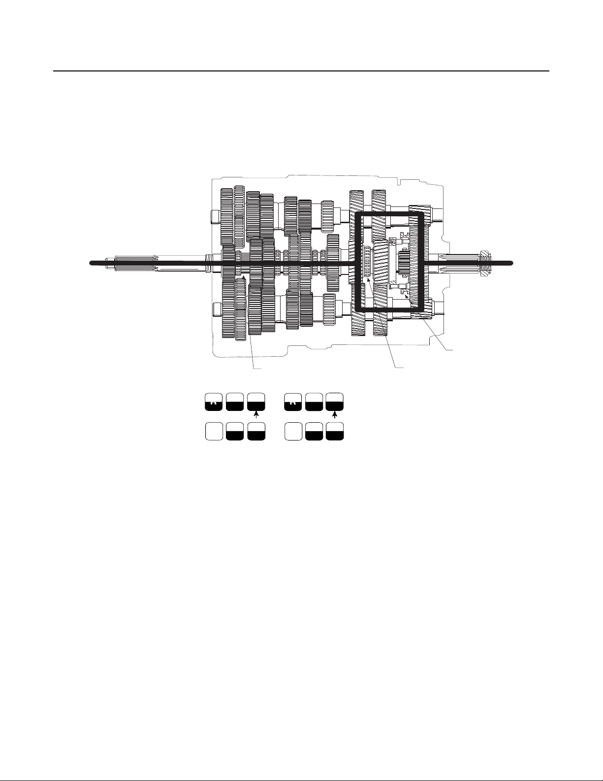
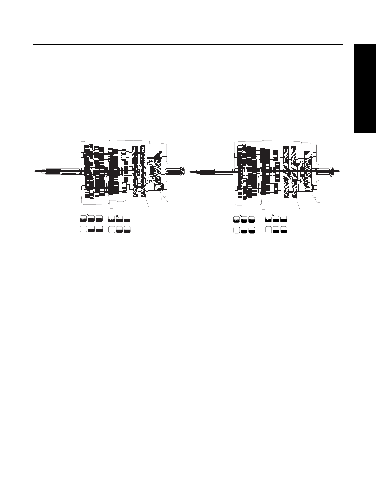
Front Section Power Flow - Direct Gear
In direct gear, the Front Sliding Clutch is moved forward and engages into the back of the Main Drive Gear. Torque will flow from
the Input Shaft to the Main Drive Gear, Main Drive Gear to Sliding Clutch, Sliding Clutch straight into the Front Section Mainshaft
which delivers the torque to the Auxiliary Splitter Clutch. See figure below.
Note: All Countershaft and Mainshaft Gears will rotate, but the gears will not be loaded.
Front Section Power Flow - Direct Gear
1. Sliding Clutch forward
2. Sliding Clutch forward
3. Sliding Clutch rearward
R
LO
RTO
153
Neutral
264
3
1
7
8
R
LO
RT
1
7
5
3
1
6
8
4
2
2
20
Power Flow
General Information
1
2
3
1
2
3
1
2
3
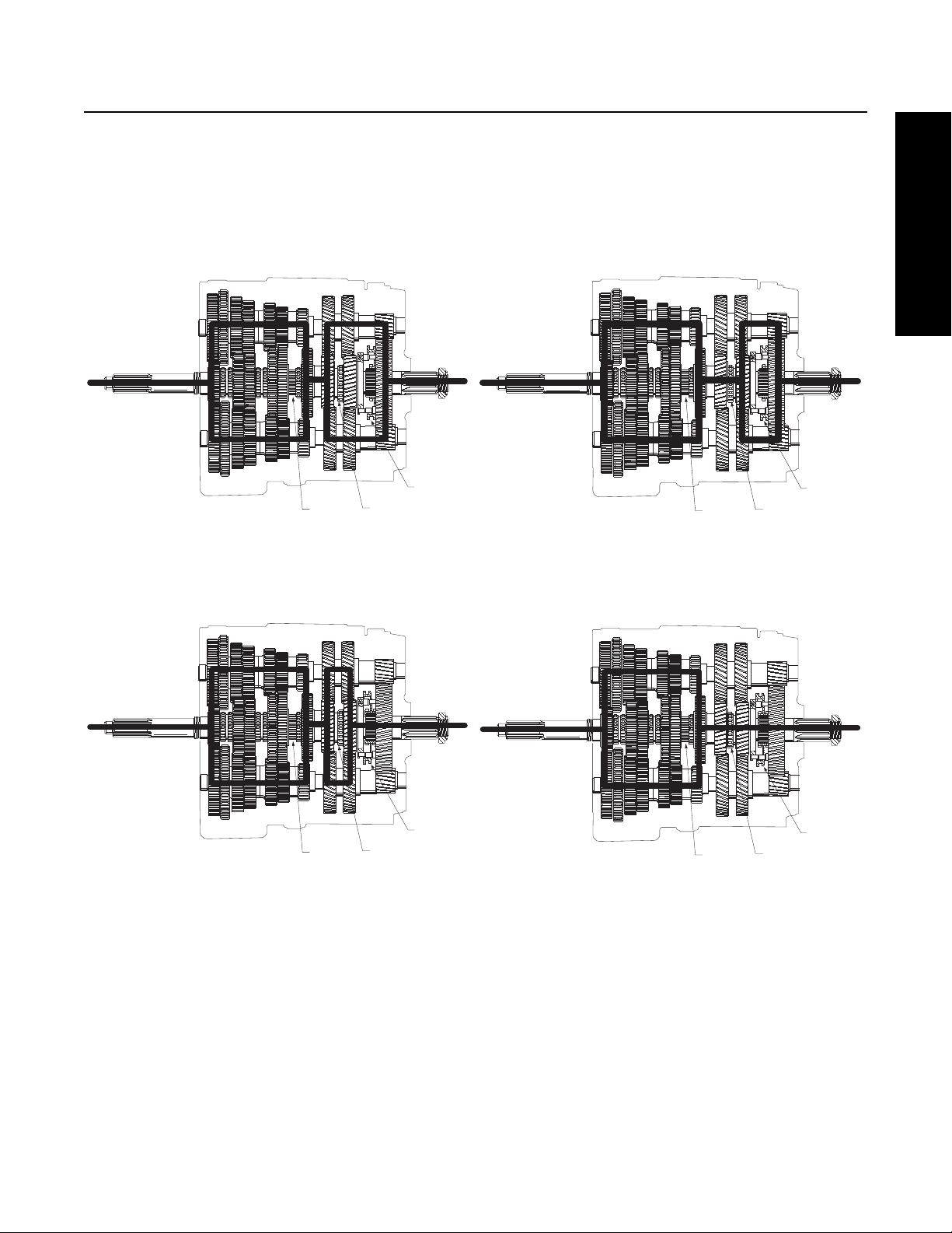
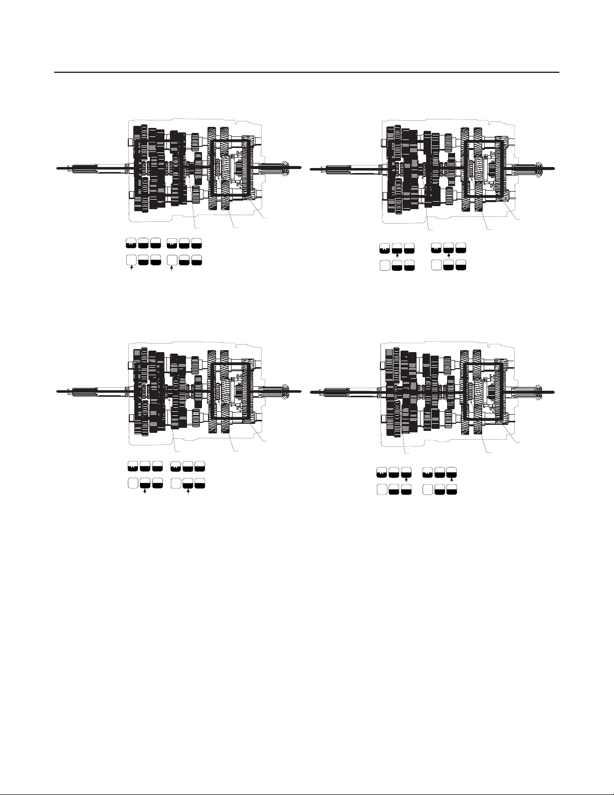
Front Section Power Flow - Reverse Gear
Torque will flow from the Countershafts to the Reverse Idler Gears. Torque will then flow from the Reverse Idler Gears to the
Mainshaft Reverse Gear. Torque will now travel through the Mainshaft Reverse Gear, the Sliding Clutch in the Reverse position
and then to the Mainshaft and Auxiliary Splitter Clutch. See figures below.
Note: The Idler Gears cause the reversal of rotation.
3
2
Reverse LO - 9/13 speed; Reverse LO - Low Split - 18 speed
1. Sliding Clutch rearward
2. Sliding Clutch forward
3. Sliding Clutch rearward
1
Reverse LO - High Split - 18 Speed
1. Sliding Clutch rearward
2. Sliding Clutch rearward
3. Sliding Clutch rearward
Reverse HI - 9/13 speed; Reverse HI - Low Split - 18 Speed
1. Sliding Clutch rearward
2. Sliding Clutch forward
3. Sliding Clutch forward
Reverse HI - High Split - 18 Speed
1. Sliding Clutch rearward
2. Sliding Clutch rearward
3. Sliding Clutch forward
21
Power Flow
1
2
3
153
7
264
8
Neutral
R
LO
RTO
154
8
263
7
Neutral
R
LO
RTX
1
2
3
153
7
264
8
Neutral
R
LO
154
8
263
7
Neutral
R
LO
RTO
RTX
Auxiliary Section Power Flow - Low Range
Depending on the position of the Splitter Button (L or H) the Auxiliary Splitter Clutch engages in either the Auxiliary Drive Gear or
the Splitter Gear. The selected Auxiliary Gear transfers torque to both Auxiliary Countershafts.
If the Auxiliary Section is in low range, the Range Sliding Clutch is rearward and engaged into the Auxiliary Mainshaft Reduction
Gear. Torque flows from the Auxiliary Countershafts, into the Auxiliary Mainshaft Reduction Gear, through the Range Sliding
Clutch and then into the Output Shaft (Auxiliary Mainshaft).
LO - 9/13 Speed; LO - Low Split - 18 Speed
1. Sliding Clutch forward
2. Sliding Clutch forward
3. Sliding Clutch rearward
LO - High Split - 18 Speed
1. Sliding Clutch forward
2. Sliding Clutch rearward
3. Sliding Clutch rearward
22
Power Flow
General Information
1
2
3
153
7
264
8
N
eutra
l
R
LO
R
TO
1
5
2
6
R
LO
R
T
3
7
4
8
1
2
3
153
7
264
8
Neutral
R
LO
154
8
263
7
Neutral
R
LO
RTO
RTX
Auxiliary Section Power Flow- High Range
If the Auxiliary Section is in high range, the Range Sliding Clutch is forward and engaged into the back of the Auxiliary Drive Gear.
Torque flows through the Auxiliary Section in high range depending on the splitter state selected (L or H). If splitter (L) is selected,
torque flows from the Auxiliary Splitter Clutch to the Auxiliary Drive Gear. From the Auxiliary Drive Gear, torque flows to both
Countershafts and then to the Splitter Gear. Torque then flows into the Range Sliding Clutch and Output Shaft. (See Figure 1st-13
Speed; 1st-Low Split-18 Speed).
If splitter (H) is selected, torque flows directly through the Auxiliary Section. Torque flows from the Auxiliary Splitter Clutch to the
Auxiliary Reduction Gear to the Range Sliding Clutch to the Output Shaft. The Auxiliary gearing still turns, but the gear teeth will
not be loaded. (See Figure 1st-High Split-18 Speed).
5th - 9/13–18 speed Low Split
1. Sliding Clutch rearward
2. Sliding Clutch forward
3. Sliding Clutch forward
5th - 9/13–18 speed High Split
1. Sliding Clutch rearward
2. Sliding Clutch rearward
3. Sliding Clutch forward
23
Power Flow
1
2
3
153
7
264
8
Neutral
R
LO
RTO
154
8
263
7
Neutral
R
LO
RTX
1
2
3
153
7
264
8
Neutral
R
LO
154
8
263
7
Neutral
R
LO
RTO
RTX
1
2
3
153
7
264
8
Neutral
R
LO
RTO
1
5
2
6
R
LO
RT
3
7
4
8
9-Speed
LO Gear
1. Sliding Clutch forward
2. Sliding Clutch forward
3. Sliding Clutch rearward
2nd Gear
1. Sliding Clutch forward
2. Sliding Clutch forward
3. Sliding Clutch rearward
1st Gear
1. Sliding Clutch rearward
2. Sliding Clutch forward
3. Sliding Clutch rearward
RTO
7
R
153
Neutral
8
LO
264
3rd Gear
1. Sliding Clutch forward
2. Sliding Clutch forward
3. Sliding Clutch rearward
3
1
1
RT
7
5
R
3
1
6
8
LO
4
2
2
24

Power Flow
General Information
1
2
3
153
7
264
8
N
eutra
l
R
LO
R
TO
1
1
5
2
6
R
LO
R
T
3
7
4
8
1
2
3
153
7
264
8
N
eutra
l
R
LO
R
TO
1
5
2
6
R
LO
R
T
3
7
4
8
1
2
3
153
7
264
8
Neutral
R
LO
RTO
1
5
2
6
R
LO
RT
3
7
4
8
1
2
3
153
7
264
8
Neutral
R
LO
RTO
1
5
2
6
R
LO
RT
3
7
4
8
4th Gear
1. Sliding Clutch rearward
2. Sliding Clutch forward
3. Sliding Clutch rearward
6th - Gear
1. Sliding Clutch forward
2. Sliding Clutch forward
3. Sliding Clutch forward
5th - Gear
1. Sliding Clutch rearward
2. Sliding Clutch forward
3. Sliding Clutch forward
7th - Gear
1. Sliding Clutch forward
2. Sliding Clutch forward
3. Sliding Clutch forward
25

Power Flow
1
2
3
153
7
264
8
Neutral
R
LO
RTO
1
5
2
6
R
LO
RT
3
7
4
8
1
2
3
153
7
264
8
R
LO
RTO
1
5
2
6
R
LO
RT
3
7
4
8
8th - Low Split Gear (Top-2 Models)
1. Sliding Clutch rearward
2. Sliding Clutch forward
3. Sliding Clutch forward
8th - High Split Gear (Top-2 Models)
1. Sliding Clutch rearward
2. Sliding Clutch rearward
3. Sliding Clutch forward
26

General Information
13 Speed - Power Flow by Gear
1
2
3
153
7
264
8
Neutral
R
LO
RTO
154
8
263
7
Neutral
R
LO
RTX
1
2
3
153
7
264
8
Neutral
R
LO
154
8
263
7
Neutral
R
LO
RTO
RTX
1
2
3
153
7
264
8
Neutral
R
LO
RTO
1
5
2
6
R
LO
RT
3
7
4
8
Power Flow
LO Gear
1. Sliding Clutch forward
2. Sliding Clutch forward
3. Sliding Clutch rearward
2nd Gear
1. Sliding Clutch forward
2. Sliding Clutch forward
3. Sliding Clutch rearward
1st Gear
1. Sliding Clutch rearward
2. Sliding Clutch forward
3. Sliding Clutch rearward
RTO
7
R
153
Neutral
8
LO
264
3rd Gear
1. Sliding Clutch forward
2. Sliding Clutch forward
3. Sliding Clutch rearward
3
1
1
RT
7
5
R
3
1
6
8
LO
4
2
2
27

Power Flow
1
2
3
153
7
264
8
N
eutra
l
R
LO
R
TO
1
1
5
2
6
R
LO
R
T
3
7
4
8
1
2
3
153
7
264
8
N
eutra
l
R
LO
R
TO
1
5
2
6
R
LO
R
T
3
7
4
8
1
2
3
153
7
264
8
Neutral
R
LO
154
8
263
7
Neutral
R
LO
RTO
RTX
1
2
3
153
7
264
8
Neutral
R
LO
RTO
1
5
2
6
R
LO
RT
3
7
4
8
4th Gear
1. Sliding Clutch rearward
2. Sliding Clutch forward
3. Sliding Clutch rearward
5th - High Split Gear
1. Sliding Clutch rearward
2. Sliding Clutch rearward
3. Sliding Clutch forward
5th - Low Split Gear
1. Sliding Clutch rearward
2. Sliding Clutch forward
3. Sliding Clutch forward
6th - Low Split Gear
1. Sliding Clutch forward
2. Sliding Clutch forward
3. Sliding Clutch forward
28

Power Flow
General Information
1
2
3
153
7
264
8
Neutral
R
LO
RTO
1
5
2
6
R
LO
RT
3
7
4
8
1
2
3
153
7
264
8
Neutral
R
LO
RTO
1
5
2
6
R
LO
RT
3
7
4
8
1
2
3
153
7
264
8
Neutral
R
LO
RTO
1
5
2
6
R
LO
RT
3
7
4
8
1
2
3
153
7
264
8
Neutral
R
LO
RTO
1
5
2
6
R
LO
RT
3
7
4
8
6th - High Split Gear
1. Sliding Clutch forward
2. Sliding Clutch rearward
3. Sliding Clutch forward
7th - High Split Gear
1. Sliding Clutch forward
2. Sliding Clutch rearward
3. Sliding Clutch forward
7th - Low Split Gear
1. Sliding Clutch forward
2. Sliding Clutch forward
3. Sliding Clutch forward
8th - Low Split Gear
1. Sliding Clutch rearward
2. Sliding Clutch forward
3. Sliding Clutch forward
29

Power Flow
1
2
3
153
7
264
8
R
LO
RTO
1
5
2
6
R
LO
RT
3
7
4
8
8th - High Split Gear
1. Sliding Clutch rearward
2. Sliding Clutch rearward
3. Sliding Clutch forward
30

General Information
18 Speed - Power Flow by Gear
1
2
3
153
7
264
8
Neutral
R
LO
RTO
154
8
263
7
Neutral
R
LO
RTX
1
2
3
153
7
264
8
Neutral
R
LO
154
8
263
7
Neutral
R
LO
RTO
RTX
Power Flow
3
RTO
7
R
153
Neutral
8
LO
264
1
RTX
8
R
154
Neutral
7
LO
263
2
LO - Low Split Gear
1. Sliding Clutch forward
2. Sliding Clutch forward
3. Sliding Clutch rearward
1st - Low Split Gear
1. Sliding Clutch rearward
2. Sliding Clutch forward
3. Sliding Clutch rearward
LO - High Split Gear
1. Sliding Clutch forward
2. Sliding Clutch rearward
3. Sliding Clutch rearward
RTO
R
153
Neutral
LO
264
1st - High Split Gear
1. Sliding Clutch rearward
2. Sliding Clutch rearward
3. Sliding Clutch rearward
3
1
RTX
7
8
8
R
154
Neutral
7
LO
263
2
31

Power Flow
1
2
3
153
7
264
8
Neutral
R
LO
RTO
1
5
2
6
R
LO
RT
3
7
4
8
1
2
3
153
7
264
8
Neutral
R
LO
154
8
263
7
Neutral
R
LO
RTO
RTX
1
2
3
153
7
264
8
Neutral
R
LO
RTO
1
5
2
6
R
LO
RTX
4
8
3
7
2nd - Low Split Gear
1. Sliding Clutch forward
2. Sliding Clutch forward
3. Sliding Clutch rearward
RTO
7
R
153
Neutral
8
LO
264
3rd - Low Split Gear
1. Sliding Clutch forward
2. Sliding Clutch forward
3. Sliding Clutch rearward
2nd - High Split Gear
1. Sliding Clutch forward
2. Sliding Clutch rearward
3. Sliding Clutch rearward
3
1
1
RT
7
5
R
3
1
6
8
LO
4
2
2
3rd - High Split Gear
1. Sliding Clutch forward
2. Sliding Clutch rearward
3. Sliding Clutch rearward
32

Power Flow
General Information
1
2
3
153
7
264
8
N
eutra
l
R
LO
R
TO
1
1
5
2
6
R
LO
R
T
3
7
4
8
1
2
3
153
7
264
8
N
eutra
l
R
LO
R
TO
1
5
2
6
R
LO
R
T
3
7
4
8
1
2
3
153
7
264
8
Neutral
R
LO
154
8
263
7
Neutral
R
LO
RTO
RTX
3
1
RTO
7
R
153
Neutral
8
LO
264
RTX
8
5
R
4
1
6
7
LO
3
2
2
4th - Low Split Gear
1. Sliding Clutch rearward
2. Sliding Clutch forward
3. Sliding Clutch rearward
5th - Low Split Gear
1. Sliding Clutch rearward
2. Sliding Clutch forward
3. Sliding Clutch forward
4th - High Split Gear
1. Sliding Clutch rearward
2. Sliding Clutch rearward
3. Sliding Clutch rearward
5th - High Split Gear
1. Sliding Clutch rearward
2. Sliding Clutch rearward
3. Sliding Clutch forward
33

Power Flow
1
2
3
153
7
264
8
Neutral
R
LO
RTO
1
5
2
6
R
LO
RT
3
7
4
8
1
2
3
153
7
264
8
Neutral
R
LO
RTO
1
5
2
6
R
LO
RT
3
7
4
8
1
2
3
153
7
264
8
Neutral
R
LO
RTO
1
5
2
6
R
LO
RT
3
7
4
8
1
2
3
153
7
264
8
Neutral
R
LO
RTO
1
5
2
6
R
LO
RT
3
7
4
8
6th - Low Split Gear
1. Sliding Clutch forward
2. Sliding Clutch forward
3. Sliding Clutch forward
7th - Low Split Gear
1. Sliding Clutch forward
2. Sliding Clutch forward
3. Sliding Clutch forward
6th - High Split Gear
1. Sliding Clutch forward
2. Sliding Clutch rearward
3. Sliding Clutch forward
7th - High Split Gear
1. Sliding Clutch forward
2. Sliding Clutch rearward
3. Sliding Clutch forward
34

Power Flow
General Information
1
2
3
153
7
264
8
Neutral
R
LO
RTO
1
5
2
6
R
LO
RT
3
7
4
8
1
2
3
153
7
264
8
R
LO
RTO
1
5
2
6
R
LO
RT
3
7
4
8
8th - Low Split Gear
1. Sliding Clutch rearward
2. Sliding Clutch forward
3. Sliding Clutch forward
8th - High Split Gear
1. Sliding Clutch rearward
2. Sliding Clutch rearward
3. Sliding Clutch forward
35

Air System
Air System Overview
Pressurized air from the vehicle's Air System is used to shift the Transmission Low/High Range and Low/High Split. The Low/High
Range and Low/High Split gearing and Shift Mechanisms are located in the Auxiliary Section of the Transmission. The vehicle
operator controls these shifts with two separate Switches on the Shift Knob (Master Control Valve). The following components
are part of the Air Shift Systems:
36
Air System
General Information
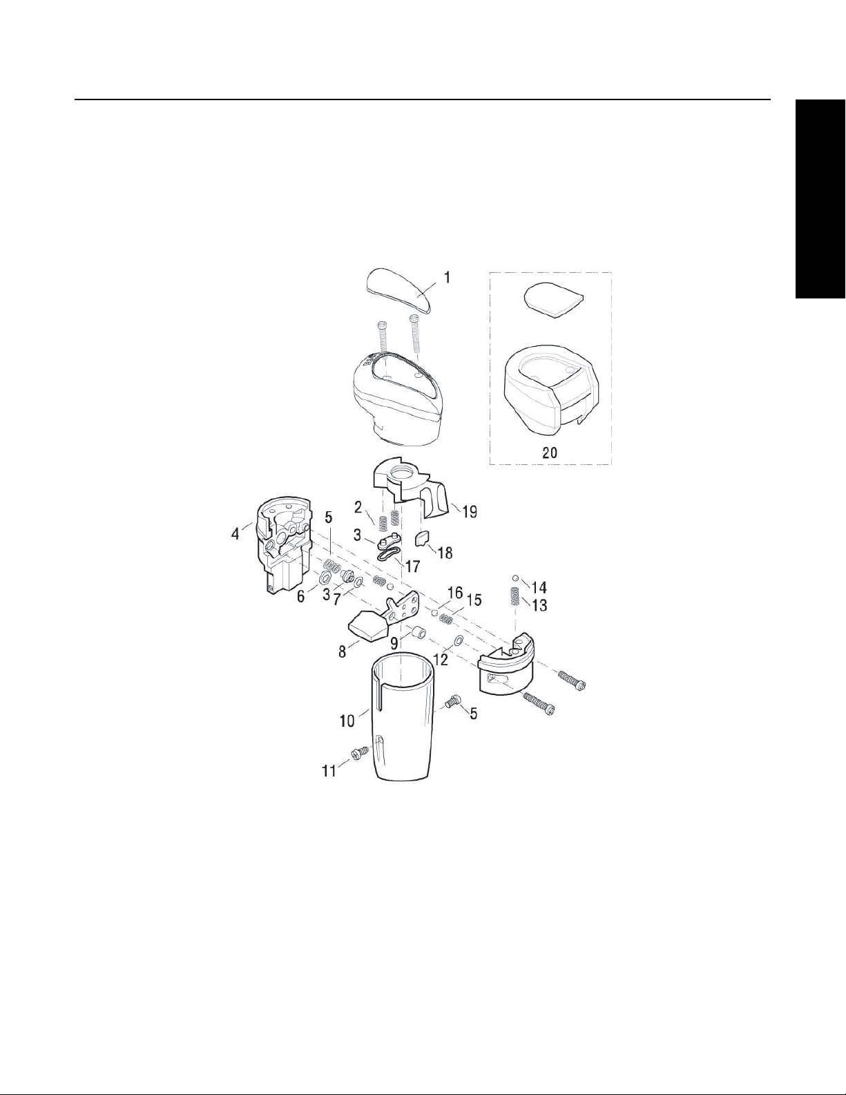
Shift Knob 13/18-Speed
The Shift Knob contains two Switches.
1. The Range Selector Lever on the front of the Shift Knob is moved down to select Low Range. When the Range Selector
Lever is moved up, High Range is selected.
2. The Splitter Button or the button on the side of the Shift Knob is moved rearward to select LO Split and forward for HI
Split of each lever position. When in LO Range a Mechanical Interlock prevents moving the Splitter Button to HI.
Component Nomenclature and Shift Knob Sectional View
1. Medallion
2. Spring
3. Retainer
4. Housing
5. Spring
6. Washer
7. O-Ring
8. Range Selector
9. Pin
10. Cover
11. Screw
12. O-Ring
13. Spring
14. 5/32" Ball
15. Spring
16. Ball
17. Seal
18. Detent
19. Splitter Button
20. Old Style Shift Knob
37

Air System
1
2
2
6
2
2
8
8
3
4
5
5
Old Design
5
5
6
7
9
Shift Knob 9-Speed
This Shift Knob contains one switch.
1. The Range Selector Lever on the front of the Shift Knob is moved down to select Low Range. When the Range Selector
Lever is moved up, High Range is selected.
Component Nomenclature and Shift Knob Sectional View
1. Medallion
2. Spring
3. Lever
4. Cover
5. Screw
6. Ball 5/32"
7. Retainer
8. O-Ring
38

Air System
General Information
Air Filter/Regulator
The Filter/Regulator Assembly filters the vehicle supply air and regulates the pressure to 58–63 PSI. Two holes in the front face
of the Filter/Regulator Assembly supply air to the Range Cylinder Cover. The Filter Element can be removed by turning out the
End Cap.
Component Nomenclature and Filter Regulator Sectional View
1. End Cap
2. O-Rings
3. Filter Element
4. Housing
5. Cap Screws
6. Air Regulator
39

Air System
9
10
11
8
12
13
6
7
5
4
3
2
1
14
15
19
18
16
Slave Valve
The Slave Valve controls the supply of air to the Low and High Range sides of the Range Shift Cylinder. A small Air Line from the
Shift Knob (Master Control Valve) provides a signal pressure to the Slave Valve.
Component Nomenclature and Slave Valve Countershaft Sectional View
1. Slave Valve Housing
2. “U” Seal
3. Washer
4. Spring
5. Plug
6. Snap Ring
7. O-Rings
8. Plate
9. Cap Screw
10. Cap
11. Gasket
12. Seal
13. O-Ring
14. Piston
15. “U” Seal
16. Cap
17. O-Ring
18. Seal
19. Spring
40

Air System
General Information
Slave Valve Pre-Selection System
This Interlock Mechanism prevents the Slave Valve from shifting when the Transmission is engaged into gear. The Air Valve Shaft
is moved towards the Slave Valve by the Shift Rails when the Transmission is shifted into gear. A spring pushes the Air Valve Shaft
back when the Front Section is shifted into a Neutral position.
Component Nomenclature and Slave Valve Countershaft Sectional View
1. Actuation Spring
2. Actuating Pin
3. Air Valve Shaft
4. Shift Bar Housing
5. Slave Valve
6. Alignment Sleeve
41

Air System
General Troubleshooting Chart
The chart on the following pages contains some of the most common problems that may occur with this Transmission along with
the most common causes and solutions.
General Troubleshooting Chart
Complaint Cause Corrective Action
Noise - Growl/Rumble Torsional Vibration.
[Noise may be most pronounced when
Transmission is in a “float” (low torque)
condition. May also be confined to a
particular vehicle speed.]
Transmission Bearing or Gear failure.
[Noise may be most pronounced under
hard pull or coast (high torque).]
Noise - Growl/Rumble at
Idle (Idle Gear Rattle)
Noise - High Pitched
Whine
Hard Lever Shifting
(Shift lever is hard to
gear into or out of gear)
Excess engine torsional vibration at idle. Check for low Engine RPM.
Gear Noise.
Isolate as to axle or Transmission noise.
If Transmission, isolate to specific gear
or gears.
Master Clutch dragging. Check Master Clutch for proper disengagement.
Shift linkage problem. (Remote Shifter) Check Shift Linkage or cables for proper adjustment,
Shift Bar Housing problem. Check Shift Bar Housing components for binding, wear,
Check driveline angles for proper U-joint working angles.
Check driveline for out of balance or damage.
Check U-joints for proper phasing.
Check Clutch Assembly for broken Damper Springs.
Check for inadequate Clutch Disc damping.
Check Transmission Oil for excessive metal particles.
Check for uneven Engine Cylinder performance.
Check for proper Clutch Damper operation.
Check for worn or defective Shift Lever Isolator.
Check for direct Cab or Bracket contact with Transmission
(“grounding”).
Check for proper Driveline U-joint working angles.
Check for damaged or worn gearing.
Check Master Clutch for proper adjustment (both Release
Bearing travel and Clutch Brake height).
binding, lubrication, or wear.
or damage.
Shift Lever Jumpout
(Shift Lever comes out
of gear on rough roads)
42
Transmission Mainshaft problem. Check Mainshaft for twist. Check Sliding Clutches for
binding, damage, or excessive wear.
Driver technique. Driver not familiar or skilled with proper double-Clutching
technique.
Driver contacting the Clutch Brake during shifts.
Loose or worn Engine Mounts. Check Engine Mounts for damage, wear, or excessive
looseness.
Shift Lever problem. Check Shift Lever Floor Boot for binding or stretching.
Check Shift Lever Isolator for excessive looseness or wear.
Check for excessive offset or overhang on the Shift Lever.
Check for extra equipment or extra weight added to Shift
Lever or Knob.
Worn or broke Detent Spring or
Mechanism.
Check for broken Detent Spring.
Check for excessive wear on the Detent Key of Detent
Plunger. Replace Detent Spring with heavier spring or add
additional spring.

General Information
General Troubleshooting Chart (Continued)
Complaint Cause Corrective Action
Air System
Shift Lever Slip-out
(Transmission comes
out of gear under
torque)
Transmission goes to
Neutral
(Shift lever doesn’t
move)
No range shift or slow
range shift
(Also see Air System
Troubleshooting)
Internal Transmission problem. Check for excessively worn or damaged Sliding Clutches
or Shift Yokes.
Low air pressure. Check Air Regulator pressure.
Internal Transmission problem. Check for excessively worn or damaged Range Sliding
Clutch or Yoke.
Transmission Air System problem. Preform Air System troubleshooting procedure.
Check for proper air signal from Master Valve.
Check Air Module Test Ports for proper air delivery.
Range cylinder problem. Check for failed or damaged Range Piston, Piston Bar, or
Cylinder.
Check for failed or loose Range Piston Snap Ring.
Range Yoke Assembly problem. Check for failed or damaged Range Yoke.
Check for failed or loose Range Yoke Snap Rings.
Check for excessively long fastener installed in rear
support hole.
Check for binding between Range Yoke Bar and Range
Alignment Lock Cover.
Grinding Noise on
Range Shift
Range Synchronizer problem. Check for failed or damaged Range Synchronizer, Sliding
Clutch, or Mating Gear.
Check for excessively worn Range Synchronizer Friction
Material.
Driver not preselecting range shift. Instruct driver to preselect range shifts.
Range Synchronizer worn or defective. Check Range Synchronizer and mating parts for excessive
wear or damage.
43

Air System
WARNING
IMPORTANT
Air System Troubleshooting
Use care when removing Air Lines or checking for air flow from disconnected Air Lines. High pressure air may exhaust
suddenly. Wear Safety Glasses. Exhaust all air pressure from system before removing Air Filter/Regulator or Combination
Cylinder Cover.
Note: During all testing, the vehicle air pressure must be greater than 90 PSI (620 kPa). If during testing the pressure falls below
90 PSI (620 kPa), make sure the Transmission is in Neutral, start the engine and let the pressure build to Governor cutoff.
After the pressure reaches the Governor cutoff, continue testing. The pressure is critical if the vehicle is equipped with a
Vehicle Air System Pressure Protection Valve that would shut off the air supply to certain air circuits if the system pressure
dropped below a preset level.
Use the following Air System troubleshooting procedures for part replacement only if the symptom can be duplicated
problem is intermittent, parts that are not defective could be replaced.
Instructions:
1. Start at “Procedures” for Step A.
2. Based on the “Result” of the procedure, go to the corresponding “What To Do Next”.
44
. If the

General Information
Air System
Procedure 1: Symptom - Air Leak at Shift Knob
Normal Operation:
• A burst of air will be exhausted from the Shift Knob when moving the Range Selector from Low to High. This is the air
being exhausted from the “P” Air Line.
• A burst of air will be exhausted from the Shift Knob when moving the Splitter Button rearward (shifting to Low split). This
is the air being exhausted from the “SP” Air Line.
Possible Causes:
• Incorrectly attached Air Lines
• Internal leak in Slave Valve
• Internal leak at Insert Valve
• Internal leak at Shift Knob
Table 10 Air Leak at Shift Knob
Procedure Result What to Do Next
Step A Remove lower skirt on Shift Knob.
Check for leaking fitting at the
Shift Knob.
Step B Check Air Lines to make sure all
lines are connected to the proper
ports on the Shift Knob.
A.) Reversal of “S” and “P” lines will
result in a constant leak from the
exhaust when High Range is
selected. B.) Reversal of the H/L and
“SP” lines will result in a constant
leak when the Splitter Button is
rearward.
Step C Move the Range Selector Lever
down to Low Range. Check for
constant air flow from the exhaust
“E” port.
Step D Move the Range Selector up to High
Range. Disconnect the small Air Line
connected to the “P” port of the Shift
Knob. Check for air flow from the
port and Air Line.
Leak found. Repair leaking fitting or Air Line.
No leak found. Go to Step B.
Air Lines are not connected to the
proper ports.
Air Lines are connected to the
proper ports.
Constant air flow from the “E” port. Replace Knob.
No air flow from “E” port. Go to Step D.
Constant air is leaking from the
“P” port or the “E” port.
Air is coming out of the
disconnected Air Line.
Air is not leaking from either port or
disconnected Air Line.
Connect lines properly.
Go to Step C.
Repair or replace the Shift Knob.
1. Verify that the Air Line is
connected to the Slave Valve
“P” port.
2. If properly connected, replace the
Slave Valve.
Go to Step E.
45

Air System
Table 10 Air Leak at Shift Knob (Continued)
Procedure Result What to Do Next
Step E Reattach the Air Line to the “P” port.
Move the Range Selector down to
Low Range and move the Splitter
Button rearward. Disconnect line
from the “SP” port. Check for air
flowing from the SP port on the
Shift Knob.
Air is flowing from the SP line. 1. Check to make sure the “SP” line
is connected to the Splitter
Cylinder Cover.
2. If the line is properly attached,
check that the Insert Valve (old
style) is properly installed (stem
facing inward) and that the Insert
Valve Bore is not defective.
3. Replace the Insert Valve.
Air is not flowing from the line. Repair or replace the Shift Knob.
46

Air System
General Information
Procedure 2: Symptom - Air Leak at Slave Valve
Normal Operation:
A momentary exhaust of air at the Slave Valve occurs during a range shift. The air from the Low Range side of the Range Cylinder is
exhausted as air pressure is applied to the High Range side. Likewise, air from the High Range side of the Piston is exhausted as air
pressure is applied to the Low Range side. The Exhaust Port is located at the Slave Valve to Transmission mounting interface.
Possible Causes:
• Internal leak in Range Cylinder.
• Internal leak in Slave Valve.
Table 11 Air Leak at Slave Valve
Procedure Result What to Do Next
Step A Confirm that air is leaking from the
Exhaust Port on the Slave Valve and not
a fitting or Air Line.
Step B Move Range Selector down to select
Low Range.
Remove the 1/4" I.D. rubber Air Line at
the High Range Supply Port on the
Range Cylinder.
Feel for air flow from the open port on
the Range Cylinder. Notice if the air leak
at the Slave Valve only occurs when the
Transmission is in High Range.
Repeat the above test but remove the
Low Range Air Hose and check with
High Range selected.
Air is leaking from fitting or
Air Line.
Air is definitely leaking from Slave
Valve Exhaust Port.
Air is flowing from High Range
Supply Port on Range Cylinder.
No air flow from High Range Port. Repair or replace Slave Valve.
Repair or replace Fitting or
Air Line.
Go to Step B.
Remove Range Cylinder Cover and
repair leaking Range Piston or
Piston Seal. After repair, check for
proper Range operation.
47

Air System
Procedure 3: Symptom - Air Leak from Transmission Breather or Transmission Case is Pressurized
Normal Operation:
There should be no measurable air flow from the Transmission Breather.
Possible Causes:
• Leak at Range Yoke Bar O-Ring
• Leak at Splitter Yoke Bar O-Ring
Table 12 Air Leak from Transmission Breather or Transmission Case is Pressurized
Procedure Result What to Do Next
Step A Listen for the air leak with the
Transmission shifted to both Low
and High Range.
Leak is only in Low Range. Remove Range Cylinder and inspect for
damaged Range Yoke Bar, Yoke Bar
O-Ring, or Range Cylinder. Repair as
necessary.
Leak is in both Low and
High Range.
Remove Splitter Cylinder. Inspect for
damaged Splitter Yoke Bar, O-Ring, or
Cylinder. Repair as necessary.
48

Air System
General Information
Procedure 4: Symptom - Air Leak at Splitter Cylinder Cover Exhaust Port
Normal Operation:
A burst of air will exhaust from this port when shifting into Low split (the Splitter Button is moved rearward while in Low Range).
Possible Causes:
• Damaged/defective Insert Valve
• Leak past Insert Valve external O-Rings
• Leak past Splitter Cylinder Piston
Table 13 Air Leak at Splitter Cylinder Cover Exhaust Port
Procedure Result What to Do Next
Step A
(old style)
Step B Remove the Splitter Cylinder Cover and piston.
Remove Insert Valve. Check for contamination,
damaged seals, or sticky movement. Check the
Insert Valve Bore in the Splitter Cylinder Cover for
contamination or damage which would result in
leakage past the Insert Valve O-Rings.
Check the piston Bore for contamination or damage.
Check the piston seals for damage.
Note: Early production Transmissions used a Paper
Gasket to seal the Splitter Cover to Cylinder, if
necessary, replace this configuration with the Spool
Valve design which uses an O-Ring.
Contamination or damage
found.
No contamination or damage
found.
Contamination or damage
found.
Repair or replace as
necessary.
Go to Step B.
Repair or replace as
necessary.
49

Air System
Procedure 5: Symptom - No or Slow Range Shift into Low
Normal Operation:
When the Range Selector on the Shift Knob is moved down to select Low Range, air pressure will flow through the Shift Knob to
the “P” port on the Slave Valve. The Slave Valve will direct air pressure through the Low Range 1/4" Rubber Hose to the Range
Cylinder to shift the range. There will be a brief burst of air at the Slave Valve as the High Range side of the Range Piston exhausts.
Likewise, when High Range is selected, the air pressure in the “P” will be exhausted at the Shift Knob. This will cause the Slave
Valve to direct air to the rear side of the Range Cylinder Piston. The air pressure on the Low Range side will be exhausted at the
Slave Valve.
Possible Causes:
• Incorrect Air Line hook up
• Insufficient air supply to Transmission
• Damaged or defective Air Filter/Regulator Assembly
• Damaged or defective Shift Knob Master Valve
• Damaged or defective Slave Valve
• Damaged or defective Range Cylinder
• Damaged or defective range Yoke or Yoke Bar
• Damaged or defective Range Synchronizer
• Damaged or defective gearing in Auxiliary Section of Transmission
Table 14 No or Slow Range Shift into Low
Procedure Result What to Do Next
Step A Place the Shift Lever in Neutral.
Check for constant air leakage at the
Shift Knob, Slave Valve, and
Transmission Case Breather when both
Low and High Range have been selected.
Step B Place Shift Lever in Neutral.
Move Range Selector up to High Range
position. At the rear of the Transmission,
disconnect the 1/4" Rubber Air Line from
the Low Range supply port on the Range
Cylinder. Check for air flow from the Low
Range port.
Step C Check for air flow from the disconnected
Air Line.
Constant air leak is detected. Go to the other corresponding
No constant leak is detected. Go to Step B.
Air flows from the Low Range
port.
No air flow from Low Range
port.
Air flows from disconnected
Air Line.
symptom first. See beginning of Air
System Troubleshooting section.
Remove Range Cylinder Cover and
repair leaking Range Piston or
Piston Seal.
Go to step C.
Go to step F.
50
No air flow from
disconnected line.
Go to step D.

General Information
Table 14 No or Slow Range Shift into Low (Continued)
Procedure Result What to Do Next
Step D Install a 100 PSI Air Gauge in the
disconnected Air Line end. With the Shift
Lever in Neutral, move the Range
Selector down to select Low Range.
Observe the Gauge.
Step E Confirm that Shift Lever is still in Neutral.
Have an assistant move the Range
Selector up and down between Low and
High Range. Does the pressure
measured at the Gauge respond rapidly
when going from High to Low.
Step F Place Shift Lever in Neutral.
At the Shift Knob, move the Range
Selection Lever up to select High Range.
At the Slave Valve, remove the Air Line
from the ‘P’ port. (should be black line).
Check for air flow from the disconnected
line.
Step G Check for air flow from the ‘P’ port on the
Slave Valve.
The Gauge read 0 PSI. Go to step F.
The Gauge reads pressure but
is lower than 58 PSI or higher
than 63 PSI.
The Gauge reads between
58–63 PSI.
Pressure rapidly changes
between 58–63 PSI and 0 at
the Gauge.
Pressure does not change
rapidly at Gauge.
Air flows from the
disconnected line.
No air flow from the
disconnected line.
Air flows from this port. Replace the Slave Valve.
No air flow from this port. Go to step H.
Air System
Replace the Filter/Regulator and check
for proper range operation.
Go to step E.
Air System appears to be operating
satisfactory. Go to step R.
1. Check for a plugged or dirty filter in
the Filter/Regulator Assembly.
2. Check for a pinched or obstructed
1/4" Rubber Air Line between the Filter/
Regulator and Slave Valve.
3. Check for a pinched or obstructed
1/4" Rubber Air Line between the Slave
Valve and the Test Gauge.
4. If all are satisfactory, go to step F.
1. Confirm that the Air Lines are
connected to the correct ports at the
Shift Knob.
2. If the lines are correct, replace the
Shift Knob.
Go to step G.
Step H Place the Shift Lever in Neutral. Install a
100 PSI Pressure Gauge in line with the
’P’ line. Move the Range Selector back
and forth from Low to High Range. The
Gauge should show rapid pressure
change.
The Gauge responds slowly. 1. Check for a restricted line between
the Shift Knob and Slave Valve.
51

Air System
Table 14 No or Slow Range Shift into Low (Continued)
Procedure Result What to Do Next
The Gauge rapidly moves
between 58–63 PSI and
0PSI.
Step I If possible, leave Air Lines attached to
Slave Valve. Unbolt the Slave Valve from
Transmission side. Check for free
movement of the Plunger Pin protruding
from the Case under the Slave Valve. The
Pin should extract when the
Transmission is shifted into gear and
retract when shifted into Neutral.
Note: If desired, the Slave Valve can be
actuated and tested while unbolted from
the Transmission Case. The Air Lines of
course, must remain attached.
Step R If Air System has been tested and found
to operate satisfactory, the Auxiliary
Section must be removed to inspect for
mechanical problem.
Remove Auxiliary Section and inspect
for:
• Binding of Range Yoke Bar or Piston
• Damaged or defective Range Yoke
• Damaged or defective Range
Synchronizer
• Cracked c/s weld resulting in gear
turning on shaft
• Damaged or defective Range Sliding
Clutch
• Auxiliary Section gearing out of time
Actuating Plunger Pin does
not move freely.
Actuating Plunger Pin moves
freely.
2. If the lines are correct, replace the
Shift Knob.
3. Check for a plugged or dirty filter in
the Filter/Regulator Assembly.
4. Check for a pinched or obstructed
1/4" Rubber Air Line between the Filter/
Regulator and Slave Valve.
5. Check for a pinched or obstructed
Air Line between the Slave Valve and
the “S” Port on the Shift Knob.
6. If all are good, replace the Shift
Knob.
Go to step I.
1. Remove Actuating Plunger Pin and
check for damage.
2. Check for missing or broken Spring.
Repair or replace Slave Valve and
check for proper range operation.
52

Air System
General Information
Procedure 6: Symptom - No or Slow Range Shift into High
Normal Operation:
When the Range Selector on the Shift Knob is moved down to select Low Range, air pressure will flow through the Shift Knob
to the 'P" port on the Slave Valve. The Slave Valve will direct air pressure through the Low Range 1/4" Rubber Supply Hose to the
Range Cylinder to shift the range. There will be a brief burst of air at the Slave Valve as the High Range side of the Range Piston
exhausts.
Likewise, when High Range is selected, the air pressure in the "P" will be exhausted at the Shift Knob. This will cause the Slave
Valve to direct air to the rear side of the Range Cylinder Piston. The air pressure on the Low Range side will be exhausted at the
Slave Valve.
Possible Causes:
• Incorrect Air Line hook up
• Insufficient air supply to Transmission
• Plugged Filter
• Incorrect Regulator pressure
• Damaged or defective Shift Knob Master Valve
• Damaged or defective Slave Valve
• Damaged or defective Range Cylinder
• Damaged or defective range Yoke or Yoke Bar
• Damaged or defective Range Synchronizer
• Damaged or defective gearing in Auxiliary Section of Transmission
Table 15 No or Slow Range Shift into High
Procedure Result What To Do Next
Step A Place the Shift Lever in Neutral.
Check for constant air leakage at the
Shift Knob, Slave Valve, and
Transmission Case Breather when both
Low and High Range have been selected.
Step B Place Shift Lever in Neutral.
Move Range Selector down to Low
Range position.
At the Transmission rear, disconnect the
1/4" Rubber Air Line from the Range
Cylinder High Range Supply Port.
Check for air flow from the Cylinder High
Range port.
Step C Check for air flow from the disconnected
Air Line.
Constant air leak is detected. Go to the other corresponding
No constant leak is detected. Go to Step B.
Air flows from the High
Range port.
No air flow from High Range
port.
Air flows from disconnected
Air Line.
No air flow from
disconnected line.
symptom first. See beginning of Air
System Troubleshooting section.
Remove Range Cylinder Cover and
repair leaking Range Piston or Piston
Seal. After repair, check for proper
range operation.
Go to step C.
Go to step F.
Go to step D.
53

Air System
Table 15 No or Slow Range Shift into High (Continued)
Procedure Result What To Do Next
Step D Install a 100 PSI air Gauge in the
disconnected Air Line end. With the Shift
Lever in Neutral, move the Range
Selector up to select High Range.
Observe the Gauge.
Step E Confirm that Shift Lever is still in Neutral.
Have an assistant move the Range
Selector up and down between Low and
High Range. Does the pressure
measured at the Gauge respond rapidly
when going from High to Low.
Step F Place Shift Lever in Neutral.
At the Shift Knob, move the Range
Selection Lever up to select High Range.
At the Slave Valve, remove the Air Line
from the "P" port. (should be black line).
Check for air flow from the disconnected
line.
Step G Check for air coming out of the Slave
Valve "P" port.
The Gauge reads 0 PSI. Go to step F.
The Gauge reads pressure but
is lower than 58 PSI or higher
than 63 PSI.
The Gauge reads between
58–63 PSI.
Pressure rapidly changes
between 58–63 PSI and 0 at
the Gauge.
Pressure does not change
rapidly at Gauge.
Air flows from the
disconnected line.
No air flow from the
disconnected line.
Air flows from this port. Replace the Slave Valve.
No air flow from this port. Go to step H
Replace the Filter/Regulator and check
for proper range operation.
Go to step E.
Air System appears to be operating
satisfactory. Go to step R.
1. Check for a plugged or dirty filter in
the Filter/Regulator Assembly.
2. Check for a pinched or obstructed
1/4" rubber Air Line between the Filter/
Regulator and Slave Valve.
3. Check for a pinched or obstructed
1/4" Rubber Air Line between the Slave
Valve and the Test Gauge.
4. If all are satisfactory, go to step F.
1. Confirm that the Air Lines are
connected to the correct ports at the
Shift Knob.
2. If the lines are correct, replace the
Shift Knob.
Go to step G.
54

General Information
Table 15 No or Slow Range Shift into High (Continued)
Procedure Result What To Do Next
Step H Place the Shift Lever in Neutral. Install a
100 PSI Pressure Gauge in line with the
"P" line. Move the Range Selector back
and forth from Low to High Range. The
Gauge should show rapid pressure
change.
Step I If possible, leave Air Lines attached to
Slave Valve. Unbolt the Slave Valve from
Transmission side.
Check for free movement of the Plunger
Pin protruding from the Case under the
Slave Valve. The Pin should extract when
the Transmission is shifted into gear and
retract when shifted into Neutral.
If desired, the Slave Valve can be
actuated and tested while unbolted from
the Transmission Case. The Air Lines of
course, must remain attached.
The Gauge responds slowly. 1. Check for a restricted line between
The Gauge rapidly moves
between 58–63 PSI and
0PSI.
Actuating Plunger pin does
not move freely.
Actuating Plunger Pin moves
freely.
Air System
the Shift Knob and Slave Valve.
2. Check for a restricted Exhaust Port
on the Shift Knob.
3. Check for a plugged or dirty filter in
the Filter/Regulator Assembly.
4. Check for a pinched or obstructed
1/4" Rubber Air Line between the Filter/
Regulator and Slave Valve.
5. Check for a pinched or obstructed
Air Line between the Slave Valve and
the “S” port on the Shift Knob.
6. If all are good, replace the Shift
Knob.
Go to step I.
1. Remove Actuating Plunger Pin and
check for damage.
2. Check for missing or broken Spring.
Repair or replace Slave Valve and
check for proper range operation.
55

Air System
Table 15 No or Slow Range Shift into High (Continued)
Procedure Result What To Do Next
Step R If Air System has been tested and found
to operate satisfactory, the Auxiliary
Section must be removed to inspect for
mechanical problem.
Remove Auxiliary Section and inspect
for:
• Binding of Range Yoke Bar or Piston
• Damaged or defective range Yoke
• Damaged or defective Range
Synchronizer
• Cracked c/s weld resulting in gear
turning on shaft
• Damaged or defective Range Sliding
Clutch
• Auxiliary Section gearing out of time
56

Air System
General Information
Procedure 7: Symptom - Range Shifts with Shift Lever in Gear
Normal Operation:
Range shift should only occur when the Shift Lever is in Neutral. The Range Selector can be moved up or down while the Shift
Lever is in a gear position, but the shift will not occur until the Shift Lever is moved to Neutral.
Possible Causes:
• Worn or missing Actuating Pin or Air Valve Shaft
• Worn Shift Rail
Procedure:
If the Range has been confirmed to shift with the Shift Lever in gear, unbolt the Slave Valve from the side of the Transmission.
Confirm that the Actuating Pin is present and that it is the proper P/N for the corresponding Slave Valve. If correct, remove the
Shift Bar Housing Assembly and check for a worn or damaged Air Valve Shaft or worn Shift Rails. Replace necessary parts.
57

Timing
General Information
Figure 2
Timing Procedures
Special Instructions
It is essential that both Countershaft Assemblies of the Front and Auxiliary Sections are “timed.” This assures proper tooth
contact is made between Mainshaft Gears seeking to center on the Mainshaft during torque transfer and mating Countershaft
Gears that distribute the load evenly. If not properly timed, serious damage to the Transmission is likely to result from unequal
tooth contact causing the Mainshaft Gears to climb out of equilibrium.
Timing is a simple procedure of marking the appropriate teeth of a gear set prior to installation and placing them in proper mesh
while in the Transmission. In the Front Section, it is necessary to time only the Drive Gear set. And depending on the model, only
the LO Range, Deep Reduction, or Splitter Gear Set is timed in the Auxiliary Section.
Procedure - Front Section
1. Marking Countershaft Drive Gear teeth: Prior to placing
each Countershaft Assembly into the Case, clearly mark the
tooth located directly over the Drive Gear Keyway as shown.
This tooth is stamped with an “O” to aid identification.
2. Marking Main Drive Gear teeth: Mark any two adjacent
teeth on the Main Drive Gear.
Mark the two adjacent teeth located directly opposite the
first set marked on the Main Drive Gear. As shown to the
left, there should be an equal number of unmarked gear
teeth on each side between the marked sets.
3. Meshing marked Countershaft Drive Gear teeth with
marked Main Drive Gear teeth: After placing the Mainshaft
Assembly into the Case, the Countershaft Bearings are
installed to complete installation of the Countershaft
Assemblies.
When installing the bearings on the left Countershaft, mesh
the Countershaft Drive Gear marked tooth with either set of
Main Drive Gear two marked teeth.
Repeat the procedure when installing the Bearings on the
Right Countershaft, make use of the remaining set of Main
Drive Gear two marked teeth to time assembly.
Figure 3
57

Timing
FR and RT Stamp Position
Procedure - Time the RT Auxiliary Section
1. Mark a tooth on the Reduction Gear with a highly visible
paint, preferably a yellow or white.
2. Mark a second tooth 180 degrees away from the first.
(Ensure the marks are in the correct position by counting
the teeth between them. You should have exactly the same
number of teeth on the Reduction Gear between the
marked teeth).
3. Locate the two stamped “O’s” on the Countershaft
Reduction Gears and mark both teeth with a highly visible
paint, preferably a yellow or white.
58

General Information
4. Use a Round File or Bar to properly align from the
Left
marked teeth on the Auxiliary Countershaft to the
Auxiliary Splitter Gear. When the Bar is lined up with the
root, between the correct teeth, you will notice it’s parallel
with the Auxiliary Countershaft. Mark both the teeth with
a highly visible paint.
Example of correct alignment
Bar in correct position parallel with the Countershaft, and
between the marked Splitter gear and Reduction Gear teeth.
Examples of Left or Right Misalignment
Timing
Right
59

Timing
5. Lay the Splitter Gear on a flat surface and mark it similar to
steps 1 and 2 of this procedure. (Make sure the teeth are
painted on both faces of the Splitter Gear front and rear).
Example showing correct view of Reduction Gear timed
to Countershaft Gears on the bench:
6. Install the Reduction Gear and Output Shaft Assembly into
the Auxiliary Case. Then, install the Auxiliary Countershafts
and Splitter Gear. (Countershaft Retaining Straps must be
used to hold the Auxiliary Countershafts in place until the
Auxiliary Section is fully installed. Failure to use the
straps could result in the Auxiliary Section moving out
of time).
Examples of Splitter Gear timed to the Auxiliary
Countershafts:
7. To ensure the timing is correct, check that the marked tooth
on the Splitter Gear is between the two marked teeth on the
Auxiliary Countershaft Gears as shown in the illustrations:
60

In-Vehicle Service Procedures
In-Vehicle Service Procedures
How to Remove Oil Filter Adapter
Special Instructions
The Oil Filter Adapter must be removed before the Transmission can be set on the table for servicing. Failure to do so will make
the Transmission unstable and may damage the Filter Adapter.
If the Transmission is not equipped with an Oil Filter Adapter at the Pump Outlet, skip this procedure.
Special Tools
• Typical Service Tools
Procedure -
1. Remove the Oil Filter by turning it in the counter-clockwise
direction.
2. From the Oil Filter Adapter, remove the (5) 3/16" Allen
Head Cap Screws.
3. Remove the Gasket and clean all mounting surfaces.
61

In-Vehicle Service Procedures
How to Assemble Oil Filter Adapter
Special Instructions
None
Special Tools
• Typical Service Tools
Procedure -
1. Position the new Gasket on the Adapter mounting surface
with (2) Cap Screws through the Adapter to hold the Gasket
in place.
2. Install the Filter Adapter and torque all Cap Screws to
8–12 lb-ft (10.85–16.30 N•m).
®
3. Install a new Oil Filter, Eaton
Part # 4304827 or equivalent.
62

In-Vehicle Service Procedures
How to Disassemble Roadranger Valve A-5010
1
2
2
6
2
2
8
8
3
4
5
5
Old Design
5
5
6
7
9
Special Instructions
None
Special Tools
• Typical Service Tools
In-Vehicle Service Procedures
Component Nomenclature and Roadranger Valve Sectional View
1. Medallion
2. Spring
3. Lever
4. Cover
5. Screw
6. Ball 5/32"
7. Retainer
8. O-Ring
9. Old Style Shift Knob
63

In-Vehicle Service Procedures
Procedure -
1. Remove the two screws holding the Bottom Cover to the Valve and slide the Cover down the Gear Shift Lever to expose
Air Line Fittings. Disconnect the Air Lines.
2. Loosen the Jam Nut and turn the Roadranger Valve from the Gear Shift Lever.
3. Pry the Medallion from the recess in the Top Cover.
4. Turn out the two screws to remove the Top Cover from the Valve Housing.
5. Turn out the two screws in the side of the Valve Housing to separate the Housing.
6. Remove the Range Selection Lever from the Left Housing along with the Position Balls and Guide.
7. If necessary, remove the Springs and O-Ring from the Bores in the Left Housing.
8. If necessary, remove the Springs, O-Ring and Sleeves from the Bores in the Right Housing.
64

In-Vehicle Service Procedures
How to Assemble Roadranger Valve A-5010
1
2
2
6
2
2
8
8
3
4
5
5
Old Design
5
5
6
7
9
Special Instructions
None
Special Tools
• Typical Service Tools
In-Vehicle Service Procedures
Component Nomenclature and Roadranger Valve Sectional View
1. Medallion
2. Spring
3. Lever
4. Cover
5. Screw
6. Ball 5/32"
7. Retainer
8. O-Ring
9. Old Style Shift Knob
65

In-Vehicle Service Procedures
Procedure -
1. Refer to the drawing for proper reassembly. Use a very small amount of Silicone Lubricant on the O-Rings to avoid clogging
the ports. A small amount of grease on the Position Springs and Balls will help to hold them in place during reassembly.
2. Reinstall Roadranger Valve on Gear Shift Lever and tighten the Jam Nut.
3. Attach the Air Lines and reinstall the Bottom Cover.
66

In-Vehicle Service Procedures
How to Disassemble Roadranger Valve A-4900
Special Instructions
None
Special Tools
• Typical Service Tools
In-Vehicle Service Procedures
Component Nomenclature and Roadranger Valve Sectional View
1. Medallion
2. Spring
3. Retainer
4. Housing
5. Spring
6. Washer
7. O-Ring
8. Range Selector
9. Pin
10. Cover
11. Screw
12. O-Ring
13. Spring
14. 5/32" Ball
15. Spring
16. Ball
17. Seal
18. Detent
19. Splitter Button
20. Old Style Shift Knob
67

In-Vehicle Service Procedures
Procedure -
1. Remove the two screws holding the Bottom Cover to the Valve and slide the Cover down the Gear Shift Lever to expose the
Air Line Fittings. Disconnect the Air Lines.
2. Loosen the Jam Nut and turn the Control Valve from the Gear Shift Lever.
3. Pry the Medallion from the recess in the Top Cover.
4. Turn out the two screws to remove the Top Cover from the Valve Housing.
5. Turn out the two screws in the side of the Valve Housing to separate the Housing.
6. Remove the Range Selection Lever from the Left Housing along with the Position Balls and Guide.
7. If necessary, remove the Springs and O-Ring from the Bores in the Left Housing.
8. If necessary, remove the Springs, O-Ring and Sleeve from the Bores in the Right Housing.
68

In-Vehicle Service Procedures
How to Assemble Roadranger Valve A-4900
Special Instructions
None
Special Tools
• Typical Service Tools
In-Vehicle Service Procedures
Component Nomenclature and Roadranger Valve Sectional View
1. Medallion
2. Spring
3. Retainer
4. Housing
5. Spring
6. Washer
7. O-Ring
8. Range Selector
9. Pin
10. Cover
11. Screw
12. O-Ring
13. Spring
14. 5/32" Ball
15. Spring
16. Ball
17. Seal
18. Detent
19. Splitter Button
20. Old Style Shift Knob
69

In-Vehicle Service Procedures
Procedure -
1. Refer to the drawing for proper reassembly. Use a very small amount of Silicone Lubricant on the O-Rings to avoid clogging
the ports. A small amount of grease on the Position Springs and Balls will help to hold them in place during reassembly
2. Install the Control Valve on the Gear Shift Lever and tighten the Jam Nut.
3. Attach the Air Lines and install the Bottom Cover.
70

In-Vehicle Service Procedures
In-Vehicle Service Procedures
How to Remove the Air Lines and Hoses
Special Instructions
Before removing the Air Lines and Hoses, label or record their location.
If you are unsure of their location, after you remove the Air Lines and Hoses, see the Air System Troubleshooting Guide TRTS0920 .
Special Tools
• Typical Service Tools
• For “Push-to-Connect” Fittings, the Eaton Service Tool Kit K-2394 is recommended. The Kit contains the Release Tool
and the Tubing Cutter.
Procedure -
1. Disconnect all Air Lines and Hoses.
2. Inspect the Air Lines and Hoses.
71

In-Vehicle Service Procedures
3. Inspect Air Fittings and remove if damaged.
72

In-Vehicle Service Procedures
How to Install the Air Lines and Hoses
Special Instructions
Make sure Air Lines and Hoses are not damaged.
Install the Air Lines and Hoses at their proper location.
In-Vehicle Service Procedures
All externally threaded 1/8" or 5/32" Air Lines and Pipe Fittings that are not coated with pre-applied thread sealant must be coated
with Eaton
All externally threaded 1/4" Air Fittings that are not coated with pre-applied thread sealant must be coated with Eaton Sealing
Material #71209 or equivalent for at least 3 complete and consecutive threads.
For the 1/4" I.D. Air Hoses, install the fixed nut end first.
To install the Air Lines and Hoses, the Air Filter/Regulator must be in position.
If you are unsure of the Air Line and Hose locations, see the Air System Troubleshooting Guide TRTS0920.
®
Sealing Material #71209 or equivalent for at least 5 complete and consecutive threads.
Special Tools
• Typical Service Tools
• For 'Push-to-Connect' Fittings, the Eaton Service Tool Kit K-2394 is recommended. The Kit contains the Release Tool
and a Tubing Cutter.
Procedure -
1. Replace damaged Air Fittings.
73

In-Vehicle Service Procedures
2. Connect the Air Lines from the Slave Valve to the
Range Cylinder.
3. Connect all removed Air Lines and Hoses.
4. Make sure the Fittings are tight and the Lines are not kinked.
74

In-Vehicle Service Procedures
In-Vehicle Service Procedures
WARNING
CAUTION
How to Remove Compression Type Fittings
Special Instructions
A sudden release of air pressure can cause personal injury or damage to equipment. To prevent injury or equipment damage,
exhaust the Vehicle Air Tanks
Small Air Lines are available in 1/8" or 5/32" sizes. Make sure 1/8" Air Lines are used with 1/8" Fittings and 5/32" Lines are
used with 5/32"Fittings. Mixing sizes can cause air leaks or damage to Fittings.
Before removing the Air Lines and Hoses, label or record their location.
Special Tools
• Typical Service Tools
Procedure -
1. Exhaust the Vehicle Air Tanks before continuing.
2. Loosen the nut on the fitting, and slide it back out of the way.
3. Pull the Air Line and attached Collet from the fitting.
4. Inspect the fitting, Air Line, Collet, and Nut for damage or
wear. Replace as necessary.
75

In-Vehicle Service Procedures
WARNING
CAUTION
How to Install Compression Type Fittings
Special Instructions
A sudden release of air pressure can cause personal injury or damage to equipment. To prevent injury or equipment damage,
exhaust the Vehicle Air Tanks
Small Air Lines are available in 1/8" or 5/32" sizes. Make sure 1/8" Air Lines are used with 1/8" Fittings and 5/32" Air Lines
are used with 5/32" Fittings. Mixing sizes can cause air leaks or damage to Fittings.
Special Tools
• Typical Service Tools
Procedure -
1. Check the threads of the fitting for thread sealant. If no
sealant is present, apply Eaton
or equivalent.
2. Install the fitting.
Note: Do not overtighten the nut. Overtightening can
compress the Collet too much and cause an
air line restriction.
3. Install the Air Line, Collet, and Nut. If installing a new fitting,
place the Collet in the fitting and loosely install the Nut. (Do
not tighten the Nut yet.) Insert the Air Line through the Nut
and into the Collet. Tighten the Nut as usual.
4. Enable the Vehicle Air System. Allow the Air Tanks to
pressurize, and check for leaks. Repair as necessary.
Thread Sealant #71205
76

In-Vehicle Service Procedures
In-Vehicle Service Procedures
WARNING
CAUTION
How to Remove Push-to-Connect Type Fittings
Special Instructions
A sudden release of air pressure can cause personal injury or damage to equipment. To prevent injury or equipment damage,
exhaust the vehicle air tank.
Make sure only 5/32" Air Lines are used with Push-to-Connect Fittings. Using sizes other than 5/32" can cause air leaks or
damage to Fittings.
Before removing the Air Lines and Hose, label or record their location.
Special Tools
• See Tool Information (see Table 8)
• For “Push-to-Connect" Fittings, the Eaton Service Tool Kit K-2394 is recommended. The Kit contains the Release Tool
and the Tubing Cutter.
Procedure -
1. Exhaust the Vehicle Air Tanks before continuing.
2. Use the Air Line Release Tool from Kit K-2394 to press
the Release Sleeve down while pulling the Air Line from
the fitting.
3. Inspect the fitting for damage or wear. Remove and
replace as necessary.
77

In-Vehicle Service Procedures
WARNING
CAUTION
How to Install Push-to-Connect Type Fittings
Special Instructions
A sudden release of air pressure can cause personal injury or damage to equipment. To prevent injury or equipment damage,
exhaust the Vehicle Air Tanks
Make sure only 5/32" Air Lines are used with Push-to-Connect Fittings. Using sizes other than 5/32" can cause air leaks or
damage to Fittings
Special Tools
• See Tool Information (see Table 5)
• For 'Push-to-Connect' Fittings, we recommend Eaton
Tubing Cutter.
Service Tool Kit K-2394. The Kit contains the Release Tool and the
Procedure -
1. Check the threads of the fitting for thread sealant. If no
sealant is present, apply Eaton Thread Sealant #71205
or equivalent.
2. Install the fitting.
3. Inspect the Air Line for burrs or deformed areas. Trim the
air line if necessary using a sharp razor blade or the Air Line
Cutting Tool from Kit K-2394. The cut must be smooth and
square. If the tubing end is deformed or burred, the
internal O-Ring in the fitting will be damaged when the Air
Line is inserted.
4. Push the Air Line into the fitting. It should insert
approximately 3/4". If it does not insert far enough or is
difficult to insert, the fitting may be damaged and should be
replaced. After inserting, give the Air Line a slight tug to
make sure the line stays in place. If line does not stay in
place, replace the fitting.
78
5. Enable the vehicle Air System. Allow the Air Tanks to
pressurize, and check for leaks.

In-Vehicle Service Procedures
How to Remove Rubber 1/4" Air Hoses
Special Instructions
For the 1/4" I.D. air Hoses, install the fixed nut end first.
Special Tools
• Typical Service Tools
Procedure -
1. Remove all Air Line Brackets and Ties.
2. Remove swivel end.
3. Remove fixed end.
In-Vehicle Service Procedures
79

In-Vehicle Service Procedures
How to Install Rubber 1/4" Air Hoses
Special Instructions
For the 1/4" I.D. air Hoses, install the fixed nut end first.
Special Tools
• Typical Service Tools
Procedure -
1. If necessary, apply Eaton Thread Sealant #71205 or
equivalent to threads.
2. Install and tighten fixed end first, then install and tighten
swivel end.
3. Replace all Air Line Brackets and Ties.
80

In-Vehicle Service Procedures
In-Vehicle Service Procedures
How to Remove the Air Filter/Regulator
Special Instructions
The Air Filter/Regulator has two (2) O-Rings located between the Filter/Regulator and the Auxiliary Section.
Special Tools
• Typical Service Tools
Procedure -
1. Remove the Air Lines from the air Filter/Regulator.
2. From the Air Filter/Regulator, remove the two (2)
Cap Screws.
81

In-Vehicle Service Procedures
How to Install the Air Filter/Regulator
Special Instructions
The Air Filter/Regulator has two (2) O-Rings located between the Filter/Regulator and the Range Cylinder Cover.
Special Tools
• Typical Service Tools
Procedure -
1. Position the Air Filter/Regulator.
2. Apply Eaton Sealant #71205 or equivalent to the two (2)
Retaining Cap Screws.
3. Install the two (2) Retaining Cap Screws, torque to
8–12 lb-ft (10.85–16.30 N•m).
82

In-Vehicle Service Procedures
In-Vehicle Service Procedures
WARNING
How to Remove a Roadranger Valve
Special Instructions
A sudden release of air pressure can injure you or damage equipment. To prevent injury or equipment damage, the Vehicle
Air Tanks must be exhausted.
Special Tools
• Typical Service Tools
Procedure -
1. From the Roadranger Valve Cover, remove the two (2)
Mounting Screws.
2. Slide the Roadranger Valve Cover down.
3. From the Air Fittings, disconnect the Air Lines.
4. From the Roadranger base, loosen the Jam Nut. Rotate the
Roadranger Valve until the Valve is removed.
5. Inspect the parts: nut, Valve Cover, Air Lines, sheathing, and
O-Rings from the Lever Shaft.
6. In the Roadranger Valve, inspect the Air Fittings, and remove
if damaged.
83

In-Vehicle Service Procedures
How to Install a Roadranger Valve
Special Instructions
To position the Roadranger Valve, the Range Lever must be to the front or the Splitter Button to the left when facing forward.
Special Tools
• Typical Service Tools
Procedure -
1. Make sure the Nut, Valve Cover, Air Lines, sheathing, and
O-Rings are in position on the Lever Shaft.
2. If previously removed, replace the Air Fittings and torque to
84–120 lb-in (9.49–13.56 N•m).
3. Place the Roadranger Valve on the Lever Shaft and rotate so
the Range Selector faces the vehicle front.
4. From the Roadranger Valve bottom, torque the Jam Nut to
35–45 lb-ft (47.45–61.01 N•m).
5. Connect the Air Lines to the Air Fittings.
6. Slide the cover into position on the Roadranger Valve.
7. Install the Roadranger Valve Cover mounting screws.
Note: Make sure the Air Lines are seated fully.
84

In-Vehicle Service Procedures
In-Vehicle Service Procedures
WARNING
Air Line
Fittings
How to Remove a Slave Valve
Special Instructions
A sudden release of air pressure can injure you or damage equipment. To prevent injury or equipment damage, the Vehicle
Air Tanks must be exhausted.
Special Tools
• Typical Service Tools
Procedure -
1. Record or mark Air Line locations.
2. Remove all Air Lines.
Note: Remove three 1/4" ID air Hoses at swivel fitting at
Range Cylinder location. Remove Air Line Bracket at
rear of Transmission. Remove Slave Valve with air
Hoses still attached.
3. Remove the Retaining Cap Screws around Valve perimeter.
4. Remove Slave Valve and Gasket.
5. From the Transmission Case, remove the Sleeve, Spring,
and Plunger Pin.
Retaining
Capscrews
Plunger
Pin
Spring
Sleeve
6. Inspect the Air Fittings, replace if damaged.
85

In-Vehicle Service Procedures
Plunger
Pin
Spring
Sleeve
Retaining
Capscrews
How to Install a Slave Valve
Special Instructions
None
Special Tools
• Typical Service Tools
Procedure -
Air Line
Fittings
1. Clean gasket surface and install Air Fittings.
2. Lightly lubricate and install plunger Pin, Spring, and Sleeve
into Case.
86
3. Install any necessary air Hoses at this time.
4. Install new Gasket.
5. Apply Eaton
Cap Screws.
6. Install the Retaining Cap Screws, torque to 8–12 lb-ft
(10.85–16.30 N•m).
Note: Make sure the Retaining Cap Screws are properly
Sealant #71205 or equivalent to the Retaining
torqued.

In-Vehicle Service Procedures
In-Vehicle Service Procedures
How to Remove the Top-2 Valve Assembly (Transmissions with Top-2 Option Only)
Special Instructions
The Air Lines must be depressurized.
Special Tools
• Typical Service Tools
Procedure -
1. From the 3-Way Connector, disconnect the Wire Harness.
2. From the Air Fittings, disconnect the Air Lines.
3. From the Top-2 Valve Assembly, remove the two (2)
Cap Screws.
Note: If necessary remove the Exhaust Breather from the
Top-2 Valve (arrow indicates location on the Valve).
87

In-Vehicle Service Procedures
How to Install the Top-2 Valve Assembly (Transmissions with Top-2 Option Only)
Special Instructions
The Air Lines must be depressurized.
Special Tools
• Typical Service Tools
Procedure -
1. Install the two (2) Retaining Cap Screws, torque to
35–45 lb-ft (47.45–61.01 N•m).
Note: Install the Exhaust Breather on the Top-2 Valve if
previously removed (arrow shows location on the
Top-2 Valve.
2. Connect the Air Lines to the Air Fittings.
Note: Replace any damaged Air Fittings or Lines.
3. Connect the 3-Way Connector to the Harness.
Note: Be sure Connector is free from dirt and debris.
88

In-Vehicle Service Procedures
In-Vehicle Service Procedures
CAUTION
How to Remove the Gear Shift Lever/Remote Shift Control
Special Instructions
The Air Lines must be disconnected from the Transmission or from the Roadranger Valve.
Different Detent Springs are available to increase or decrease shifting effort. Note and record specific locations for specific springs.
In some cases, a stiffer spring is installed in the top rail position.
Remote Control Housings are removed the same way as Gear Shift Levers.
Special Tools
• Typical Service Tools
Procedure -
1. From the Gear Shift Lever Base/Shift Control Housing,
remove the four (4) Retaining Cap Screws.
2. To break the Gasket seal, lightly jar the Gear Shift/Shift
Control Housing.
3. Remove the Gear Shift Lever Housing.
Make sure the Detent Springs do not fall into the
Transmission.
4. Remove Detent Springs as needed.
5. Remove the Gasket and clean the area the Replacement
Gasket will contact.
89

In-Vehicle Service Procedures
How to Install the Gear Shift Lever/Remote Shift Control
Special Instructions
Remote Control Housings are installed the same way as Gear Shift Levers.
For Standard and Forward Shift Bar Housings, make sure the Detent Springs and Balls are in the Shift Bar Housing top Bores.
Make sure the Shift Block and Yoke Notches are aligned in the Neutral position.
Special Tools
• Typical Service Tools
Procedure -
1. Thoroughly clean mounting surface.
2. Position a new Gear Shift Lever/Shift Control Housing
Gasket on the Gear Shift Lever mounting surface.
3. Install the Detent Springs.
4. Install the Shift Lever/Shift Control Housing. Make sure the
tip (finger) of the Gear Shift Lever fits into the slots in the
Shift Block.
5. Apply Eaton
Cap Screws.
6. Install the Retaining Cap Screws, torque to 35–45 lb-ft
(47.45–61.01 N•m).
Note: Make sure the Cap Screws are properly torqued.
Note: Make sure you can shift the Transmission.
Sealant #71205 or equivalent to the Retaining
90

In-Vehicle Service Procedures
In-Vehicle Service Procedures
How to Adjust the Remote Shift Control (LRC Type)
Special Instructions
The following is a typical adjustment procedure for an LRC type slave control. It is recommended that the OEM Chassis Service
Manual be consulted first.
Special Tools
• Typical Service Tools
Procedure -
1. Move the Gear Shift Lever forward or backward to the
Neutral position.
2. Move the Gear Shift Lever sideways, toward Reverse,
until you feel resistance from the Reverse Plunger Spring.
DO NOT shift to Reverse. The Shift Finger must remain in
this position while you are making all the adjustments.
3. Remove the Cotter Pin, Castle Nut and Ball Joint A (see
figure A) from the Selection Lever. Do not remove the Ball
Joint from the Pivot Link.
4. Loosen the Cap Screw B (see figure A) and remove the
Shift Arm from the inner Shift Shaft. Do not disconnect the
Selection Lever from the Shift Arm.
5. Turn the Shift Arm until it is at a right angle (90°) to the
Selection Lever as viewed from the side (see figure B).
Note: Ideally, the Shift Arm should be adjusted 90° to the
Selection Lever as described, but in some Chassis
configurations it may be necessary to index the
Shift Arm in the vertical position. Indexing the
Shift Lever is done to prevent Shift Lever jump out.
This type of adjustment will cause an unequal amount
of Gear Shift Lever travel between Neutral and a
forward lever position as compared to Neutral and a
rearward lever position.
6. Install the Shift Arm on the Splines of the inner Shift Shaft.
You may have to move the Shift Arm 4 or 5 to align the
Splines of the two parts. Disregard any movement of the
Gear Shift Lever at this point. The Gear Shift Lever will be
adjusted later.
91

In-Vehicle Service Procedures
7. Tighten the Cap Screw B (see figure A) on the Shift Arm.
8. Connect the Pivot Link assembly Ball Joint to the Selection
Lever. Secure it with the Castle Nut and Cotter Pin.
9. Loosen the Jam Nuts C (see figure C) on the Pivot Link.
10. Check to be sure the inner Shift Finger is still in place.
11. Rotate the Pivot Link until the curved end of the Selection
Lever is parallel with the Shift Arm as viewed from the rear
(see figure C).
12. Tighten the Pivot Link Jam Nuts C (see figure C).
13. Loosen both Cap Screws on the Turnbuckle D (see figure A).
14. Check to be sure inner Shift Finger is still in place.
15. Rotate the Turnbuckle to obtain the proper forwardbackward Neutral position of the Gear Shift Lever in the cab.
16. Tighten one Turnbuckle D Cap Screw (see figure A).
17. Move the Gear Shift Lever to the desired position.
18. Turn the second Turnbuckle D Cap Screw.
19. Check for linkage obstructions in all gear positions.
92

In-Vehicle Service Procedures
In-Vehicle Service Procedures
Neutral Switch Operation and Testing
Special Instructions
The Neutral Switch is a normally closed switch. An electrical current flows through it when the Transmission Shifter is in the
Neutral position. When the Transmission Shifter is in gear, the Switch is open and no current flows through it. Likewise, the Switch
is open when the Ball is depressed. The Switch is actuated by the Air Valve Shaft.
Special Tools
• Typical Service Tools
• Volt/Ohm Meter
Procedure -
1. Disconnect the wiring from the Switch.
2. Connect an Ohm Meter to check for continuity or a
small reading.
3. Place the Transmission Shift Lever in the Neutral position.
The Ohm Meter should register continuity or a small
reading. If it does, go to the next step. If it does not, remove
the Switch and replace it.
4. Shift the Transmission into all gear positions. The Ohm
Meter should read Open or Infinity. If it does not, remove the
Switch. Then, depress the Switch ball and check for
continuity. The Ohm Meter should read Open or Infinity
when the Ball is depressed.
5. Look into the Neutral Switch hole and verify that the Air
Valve Shaft moves as the Transmission is shifted from
Neutral into gear.
a. If it does, replace the Switch.
b. If not, remove the Shift Bar Housing and check the
Air Valve and Shift Rails for excessive wear. Also, check
the Slave Valve Plunger and Spring for free movement.
93
 Loading...