

Page 1

Troubleshooting Guide
Fuller Transmissions
TRTS0070
October 2007
RTLO-11610B
RTLO-11610B-T2
RTLO-12610B
RTLO-12610B-T2
RTLO-12713A
RTLO-12913A
RTLO-13610B
RTLO-13610B-T2
RTLO-14610A
RTLO-14610B
RTLO-14610B-T2
RTLO-14613B
RTLO-14618A
RTLO-14713A
RTLO-14718B
RTLO-14913A
RTLO-14918B
RTLO-14918B-T2
RTLO-15610B
RTLO-15610B-T2
RTLO-16610B
RTLO-16610B-T2
RTLO-16618A
RTLO-16713A
RTLO-16713A-T2
RTLO-16718B
RTLO-16913A
RTLO-16913A-T2
RTLO-16918B
RTLO-16918B-T2
RTLO-17610B
RTLO-17610B-T2
RTLO-18610B
RTLO-18610B-T2
RTLO-18718B
RTLO-18718B-T2
RTLO-18913A
RTLO-18913A-T2
RTLO-18918B
RTLO-18918B-T2
RTLO-20913A
RTLO-20918B
RTLO-20918B-T2
RTLO-22918B
RTLOC-16909A-T2
RTLOF-11610B
RTLOF-11610B-T2
RTLOF-12610B
RTLOF-12610B-T2
RTLOF-12713A
RTLOF-12913A
RTLOF-13610B
RTLOF-13610B-T2
RTLOF-14610B
RTLOF-14610B-T2
RTLOF-14613B
RTLOF-14618A
RTLOF-14713A
RTLOF-14718B
RTLOF-14913A
RTLOF-14918B
RTLOF-14918B-T2
RTLOF-15610B
RTLOF-15610B-T2
RTLOF-16610B
RTLOF-16610B-T2
RTLOF-16618A
RTLOF-16713A
RTLOF-16713A-T2
RTLOF-16718B
RTLOF-16913A
RTLOF-16913A-T2
RTLOF-16918B
RTLOF-16918B-T2
RTLOF-17610B
RTLOF-17610B-T2
RTLOF-18610B
RTLOF-18718B
RTLOF-18913A
RTLOF-18913A-T2
RTLOF-18918B
RTLOF-18918B-T2
RTLOF-20913A
RTLOF-20918B
RTLOF-20918B-T2
RTLOF-22918B
RTLOFC-16909A-T2
Page 2

For parts or service call us
Pro Gear & Transmission, Inc.
1 (877) 776-4600
(407) 872-1901
parts@eprogear.com
906 W. Gore St.
Orlando, FL 32805
Page 3

General Warnings
General Warnings
Before starting a vehicle:
1. Sit in driver’s seat
2. Place shift lever in neutral
3. Set the parking brake
working on a vehicle or leaving the cab with engine
Before
running:
1. Place shift lever in neutral
2. Set parking brake
3. Block wheels
not release the parking brake or attempt to select a gear
Do
the air pressure is at the correct level.
until
parking the vehicle or leaving the cab:
When
1. Place shift lever in neutral
2. Set the parking brake
not operate if alternator lamp is lit or if gauges indicate low
Do
.
voltage
ry (+) and (-) must be disconnected prior to any type of
Batte
g on the vehicle.
weldin
Suggested Tools:
• Volt/Ohm Meter
SPX
/ Kent-Moore 1 (800) 328-6657
P/N
5505027
• PC-based Service Tool “Service Ranger”
Con
tact your OEM
• Data Link Tester
Ea
ton Service Parts 1 (800) 826-4357
P/N MF-KIT-04
• Shift Lever Tester
Ea
ton Service Parts 1 (800) 826-4357
691795
P/N
• Eaton Test Adapter Kit
/ Kent-Moore 1 (800) 328-6657
SPX
P/N J-43318
• 6-Pin Deutsch Diagnostic Adapter
/ Kent-Moore 1 (800) 328-6657
SPX
J-38500-60A
P/N
information and assistance, call the Roadranger Help
For
at 1-800-826-HELP (4357) (Mexico: 01-800 826-HELP
Desk
(4357). You may also find more information about Eaton
Transmissions at www.Roadranger.com.
Fuller
ry effort has been made to ensure the accuracy of the
Eve
information
ration
informatio
contained in this manual. However, Eaton Corpo-
makes no warranty, expressed or implied, based on the
n provided.
Page 4

Table of Contents
Introduction
Introduction ............................................................ 1-1
Diagnostic Procedure ............................................. 1-2
Suggested Test Fixures
Suggested Test Fixures .......................................... 1-3
General Procedures
Top 2 Basic Operation and Overview ...................... 1-5
System Problem ..................................................... 1-8
Driving Techniques
Driving Techniques ............................................... 1-12
Fault Code Isolation Procedure Index
Fault Code Isolation Procedure Index ................... 1-14
Pretest
Pneumatic Pretest .................................................. 2-1
Fault Code Procedures
Fault Code: 62
(SID: 26,40,53-56, FMI: 3,4)
DDEC III - Shift Solenoid or Lockout
Solenoid ......................................................... 2-4
Fault Code: 537, 536
(SID: 40, 51, FMI: 11)
Cummins - Shift Solenoid or Lockout
Solenoid ......................................................... 2-8
Fault Code: 66,67
(SID: 40,51, FMI: 5,6)
Caterpillar - Shift Solenoid or Lockout
Solenoid ....................................................... 2-12
Fault Code: 44,43
(SID: 10,11, FMI: 3,4)
MACK - Shift Solenoid or Lockout
Solenoid ....................................................... 2-16
Fault Code: 62
(SID: 26,40,53-56, FMI: 7)
DDEC III - Mechanical System Not
Responding .................................................. 2-20
Fault Code: 544
(PID: 191, FMI: 7)
Cummins - Mechanical System Not
Responding .................................................. 2-26
Fault Code: 68
(PID: 191, FMI:7)
Caterpillar - Mechanical System Not
Responding .................................................. 2-32
FaultCode: 38
(PID: S32, FMI: 7)
MACK - Mechanical System Not
Responding ...................................................2-38
Symptom Procedures
Symptom Driven Diagnostics Table ........................3-1
Air Leak Test - T2 Convertible Only .........................3-2
Air Leak Test - 10 Speed Onoy.................................3-6
Air Leak Test - 13 and 18 Speed Only....................3-10
Splitter System Test ..............................................3-14
Appendix
Service Information ............................................... A-1
Top 2 System Overview .......................................... A-2
Splitter Cylinder Assembly -
10 Speed Only (old design) ............................ A-9
Splitter Cylinder Assembly -
RTL-XX710 Model (latest design) ................ A-11
Splitter Cylinder Assembly -
RTLO-XX713 and XX718 (old design) .......... A-13
Splitter Cylinder Assembly -
RTLO-XX710 Model (latest design) ............. A-16
Splitter Cylinder Assembly -
RTLO-XX913 and XX918 (latest design) ...... A-18
Table of Contents
Page 5

Fault Isolation Procedures
Introduction
Purpose and Scope of Manual
This manual is designed to provide detailed information necessary to perform diagnostic and troubleshooting procedures for the
Eaton Fuller transmissions listed on the cover.
How to Use This Manual
The key to using this manual is to follow the Diagnostic Procedure (see page 1-2) first. This procedure takes you step-by-step
through the tests and procedures to help to diagnose the transmission failure.
1-1
Page 6

General Procedures
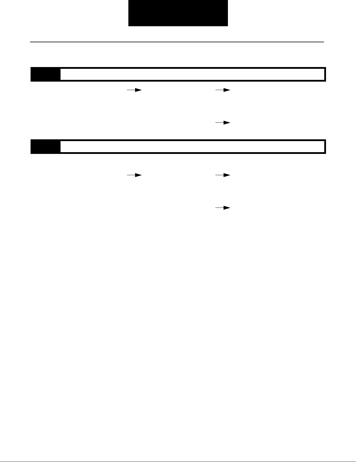
Diagnostic Procedure
Follow the flowchart below for all Top 2 transmission failures. Perform tests and procedures in order as directed by the flowchart.
It is recommended to use the MPSI Pro-Link 9000 Diagnostics Tool or an approved engine manufacturers diagnostic tool to
diagnose Fault Codes.
Key on.
Retrieve active engine codes.
Active engine
codes?
NO
Is Top 2 operating
properly?
NO
Retrieve active transmissions codes.
Active transmission
codes?
NO
YES
YES
YES
• Diagnose and repair active engine
codes per OEM recommendations.
• Clear active and inactive codes
with MPSI scan tool.
• Test drive and confirm
vehicle repair.
• Perform Electrical Pretest.
• Refer to the Fault Code Isolation
Procedure Index to select a Fault
Code Isolation Procedure.
Diagnostic Procedure
Retrieve Inactive Codes.
Inactive Codes?
NO
Symptom?
NO
Test complete.
YES
YES
• Record and clear codes.
• Perform Pneumatic Pretest.
• Perform Driving Technique to
reproduce the inactive fault code.
• Refer to Symptom-Driven Diagnostics Table to select a symptom
isolation procedure.
• Perform Pneumatic Pretest.
• Refer to Top 2 Basic Operation
and Overview section.
1-2
Page 7

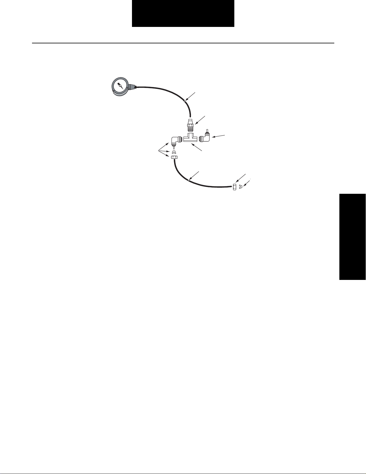
Suggested Test Fixures
Note: Only one gauge required.
Range Cylinder
Suggested Test Fixures
2
1
3
1. 0-100 PSI gauge
2. 5/32" air line
3. 5/32" push-to-connect to 1/8" NPTF
1/8" Air Lines
5
4. 1/8" nipple
5. 1/8" tee
2
1
3
4
6
5
7
4
8
9
1. 0-100 PSI gauge
2. 5/32" air line
3. 5/32" push-to-connect to 1/8" NPTF
4. Elbow
1-3
5. 1/8" tee
6. Elbow assembly
7. 1/8" air line
8. Grip nut
9. Compression sleeve
Page 8
5/32" Air Lines
Suggested Test Fixures
2
1
3
4
1. 0-100 gauge
2. 5/32" air line
3. 5/32" push-to-connect to 1/8" NPTF
4. Elbow
6
5
7
8
9
5. 1/8" Tee
6. Elbow assembly
7. 5/32" air line
8. Grip nut
9. Compression sleeve
Suggested Test Fixures
1-4
Page 9

General Procedures
Top 2 Basic Operation and Overview
The Top 2 transmission shifts like a normal 10, 13, or 18 speed transmission until the lever is put into the Auto (Top 2) Mode. The
transmission shifts automatically between the top two gears based on engine speed and load.
When the transmission is in the Auto Mode the system will:
a. Shift the transmission between the top two gears.
b. Increase or decrease engine speed during a shift.
c. Momentarily interrupts cruise control or engine brake during the shift, then resumes.
Upshift Procedure
1. Upshift the transmission through the shift pattern 7th H position for the 13/18-speed Convertible models and 8th gear
for 10-speed models. Double-clutching during lever shifts and breaking torque during button shifts.
2. When the engine has reached the shift point use the normal double-clutching procedure and move the shift lever into
AUTO gear.
Note: The position of the shift button does not matter when moving the lever into the AUTO position. It is recommended to leave
the shift button in the forward position so it is ready when you want to make a downshift into 7th H position for 13/18-speed
models or 8th gear for 10-speed models.
3. When the engine has reached the shift point the transmission will automatically shift into high gear.
Downshift Procedure
1. To downshift from high gear into the AUTO position:
Once the engine has reached the shift point the transmission will automatically downshift.
2. To downshift from AUTO position:
a. Make sure the shift button is in the forward position.
b. Once the engine has reached the shift point move the lever to the next lower lever position while double-clutching.
3. Continue downshifting through the shift pattern, double-clutching during lever shifts and breaking torque during button
shifts.
1-5
Page 10

Driving Tips
General Procedures
Top 2 Basic Operation and
• When the transmission is making a shift in the AUTO Mode, depressing the clutch pedal or moving the lever into the
neutral position may cause the Top 2 to miss the shift.
• To activate Top 2 Mode, the transmission must be shifted to the highest lever position when the engine has reached its
normal shift point of at least 1400 rpm and vehicle speed is at least 40 mph. (Example: On a Super 10 the highest lever
position is 9th and 10th gears).
• Shifting the lever into the Auto position below 1400 rpm does not activate the AUTO Mode. If the operator moves the
shift lever into the Auto lever position below the engine’s normal shift point, the transmission remains in MANUAL MODE.
• Shift points in AUTO Mode vary depending on the following things:
1. Throttle Position
2. Engine Load
3. Engine Brake Status
4. Terrain
• HOLD Mode is available when the Top 2 Cruise option is enabled. The cruise option allows the operator to turn off the
Top 2 function with the master cruise switch. When the AUTO position and Cruise Control is turned OFF, the transmission
holds in the current gear disabling auto and manual split shifts until one of the following happens:
1. The Cruise Control is turned back ON.
2. The lever is moved to the neutral position.
3. The clutch pedal is fully depressed.
• Transmission HUNTING may occur under certain driving conditions. Raising or lowering vehicle cruise speed alleviates
this condition.
Overview
1-6
Page 11

General Procedures
Definitions
Break Torque Releasing engine power or load from the transmission and drivetrain by releasing the throttle or depressing
the clutch pedal.
Double-Clutch The shifting technique used when moving the shift lever to the next lever position. Procedure: Depress
clutch pedal, move lever to neutral, let up clutch pedal, accelerate or decelerate engine to obtain synchronous, depress clutch pedal again, and move lever into gear.
Preselect Moving the shift button just prior to the starting shift. The shift button should not be moved while the shift
lever is in neutral.
Ratio Step Amount of change between two gear ratios expressed as a percentage. Example: The ratio step from 1st gear
to 2nd gear is 35%.
Shift Button The button on the side of the shift knob used to change gears.
Synchronous The point at which the input gearing speed (engine speed) matches the output gearing speed (road speed)
and a shift can occur without grinding.
Auto Position The highest lever position where the Top 2 shifts between the top two gear positions, also referred to as Top
2 Mode.
Hold Mode The transmission holds the current gear at the request of the driver by turning off the Cruise Control switch
while in the AUTO mode.
Manual Mode Driver operated splitter shifts when in the AUTO position.
Hunting A condition causing the transmission to upshift and downshift repeatedly. This condition is dependent on
road speed, throttle position, and engine load.
1-7
Page 12

Fault Isolation Procedures
C
ode
FMI
Code 62
Note:
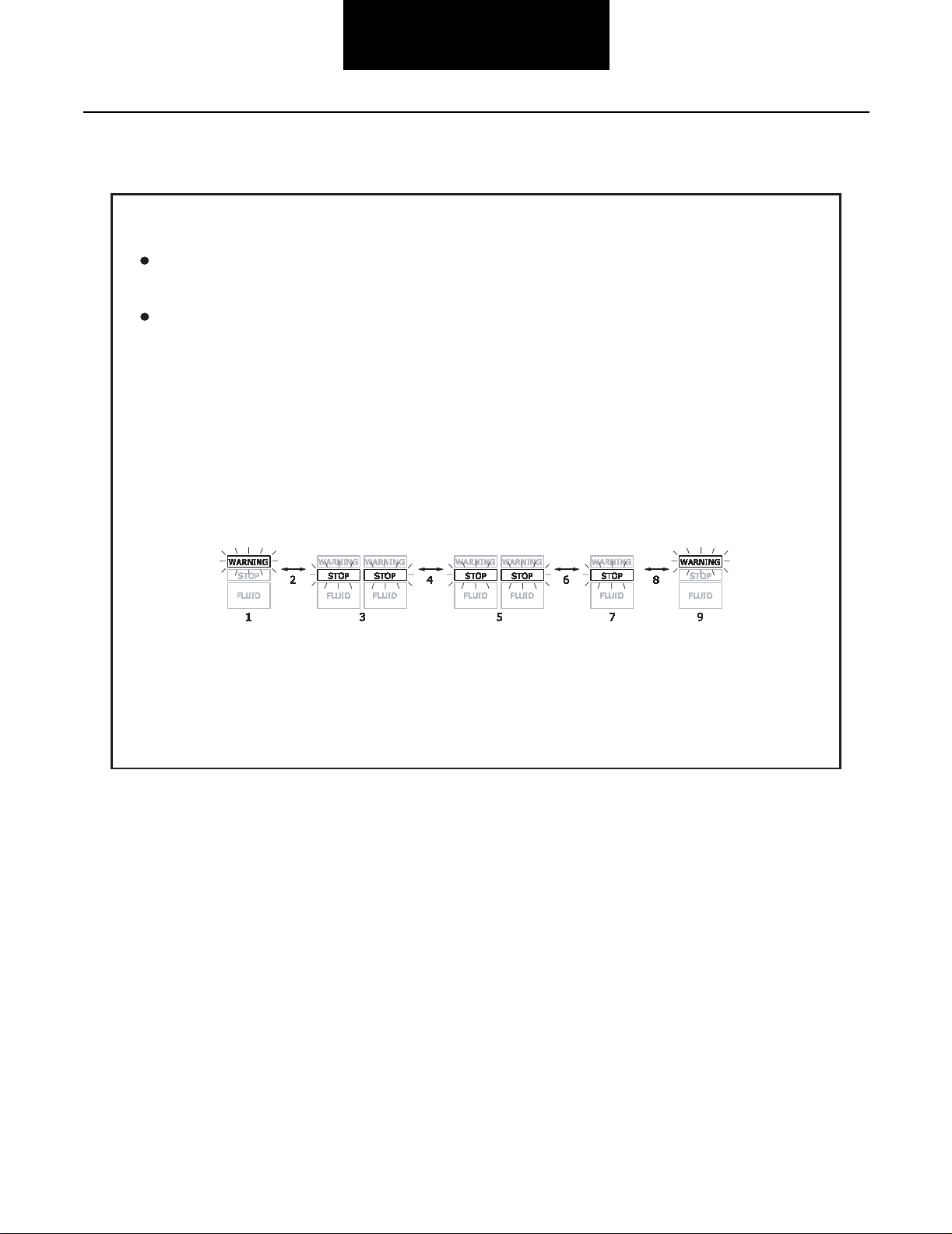
Clearing DDEC Fault Codes
Retrieving DDEC Fault Codes
System Problem
If the system malfunctions, the transmission defaults to manual mode or hold mode indicating one the following faults occurred:
• The Top 2 Valve experienced an open or short in the circuit. The check engine light turns on and the system defaults to
Manual Mode.
• A failed component in the system prevented the splitter system from making the shift. After three (3) attempts made over
a time period of about 9 seconds the system times out. The check engine light does not turn on. Shifting the transmission
to neutral or depressing the clutch obtains manual shifting mode. The Top 2 function is inactive until the vehicle is
stopped and the key is turned off for at least 10 seconds.
Fault Code Retrieval/Clearing
The procedure for retrieving and clearing fault codes differs between engine OEMs. Here are the procedures for Detroit Diesel,
Caterpillar, Cummins, and Mack.
Detroit Diesel
Code Retrieval/ Clearing
System Problem & Fault
Retrieving DDEC Fault Codes
All transmission related faults are identified by Code 62.
Fault isolation is determined by the FMI code that can only
be retrieved with a diagnostic tool. The MPSI Pro-Link 9000
diagnostic tool must be used to accurately diagnose the Top
2 system.
ode
Code 62- Shorted Circuit
Fault
Fault Code 62- Open Circuit
Fault Code 62- Mechanical System Not
Flash codes may be retrieved by manually flashing the codes
Responding
on the check engine light to retrieve the nature of the system
fault but when performing troubleshooting diagnostics a
diagnostic tool must be used to prevent misdiagnosis.
FMI
3
4
7
The following illustrates a code flashing sequence
for code 62:
1. 6 Flashes
2. Short pause (1/2 sec)
3. 2 Flashes
Code 62
After the engine lights have been activated:
Active fault codes are flashing on
the Stop Engine light.
Inactive fault codes are flashing on
the Check Engine light.
Note:
If there are no fault codes, a fault code
25 is flashed.
Clearing DDEC Fault Codes
Use an MPSI Pro-Link 9000 diagnostic tool
to clear fault codes.
1-8
Page 13
Cummins
Retrieie
ving
Cummins Fa
ult
Codes
Stop
Warning
Tomomovevetoto
the next c
ode:
Tomomovetoto
the prerevi
ous
code::::
NOTE:
Cl
earing
Cummins Faulult Cododeses
C
ode 221
R
ving
Cummins
ult
General Procedures
Codes
There are two methods of retrieving the fault codes:
Using a Cummins-approved diagnostic tool to
retrieve active and inactive fault codes.
Manually flashing the active codes on the Stop
Warning
procedure:
1. Key off.
2. Turn the Diagnostic switch on or connect
the shorting plug to the diagnostic connector.
3. Key on.
The followingillustrates a code flashingsequence fora
code 221:
1. 1 Flash
2. Short pause (2 sec)
3. 2 Flashes
4. Short pause (1or 2sec)
5. 2 Flashes
lights on the cab panel using the following
6. Short pause (1 or 2 sec)
7. 1 Flash
8. Short pause (1 or 2 sec)
9. 1 Flash
and
ode
After the lights have been activated, the lights will
continue to flash the same color.
the
switch to the + position.
the
Adjustswitchto the-position.
NO
come on and stay on.
Go tothe Fault code listing. See fault code list located
inside this troubleshooting guide.
earing
Use a Cummins-approveddiagnostic tool to clear fault
codes.
If there are no active faultcodes bothlightswill
Cummins
ode
MovetheIdleSpeedAdjust
ous
code
MovetheIdleSpeed
1-9
Page 14

Caterpillar (CAT)
Retrieie
ving CAT F
ault
Codes
Code6262
Check Engine
Clea
ring CAT F
ault
Codes
Check
Engine
Check Engine
Check Engine
Note:
R
ving
ault
Fault Isolation Procedures
Codes
There are two methodsof retrieving the fault codes:
Usinga Caterpillar-approved diagnostic tool
to retrieve the active and inactive fault codes
Manually flashing the codes on the Check
Engine
light using the following procedure:
1. Make sure the Cruise Control switch is
off.
2. Hold the Set/Resume in either Set or
Resume position until the Check Engine
light begins to flash. Release the switch
when the light begins to flash.
Go to the Fault Code listing. See fault code
list located on the inside of this troubleshooting
guide.
The following illustrates a code flashing sequence
for code 62:
Code Retrieval/ Clearing
1. 6 Flashes
2. Shortpause (1/2sec)
After the Check Engine
the active fault codes and logged codes since powerup are flashed on the Check Engine
If there are no fault codes, a fault code 55 is
Note:
flashed.
ring
Use a Caterpillar-approved diagnostic tool to clear
fault codes.
ault
Codes
3. 2 Flashes
Code
light has been activated, both
light.
System Problem & Fault
1-10
Page 15

Mack (V-MAC III)
Retrieie
ving V–MAMAC III F
ault
Codes
Code4242
Malfunction Lamp
Clearing Mack Fault Codes
Note:
R
ving
There are twomethods of retrievingthe faultcodes:
Using a MPSI Pro-Link 9000 diagnostic tool to
retrieve active and inactive fault codes.
Manually flashing the active codes on the
Malfunction Lamp
V-MAC Service Diagnostics
1. Key on-wait for two-second power up test
on lamp.
2. Lamp remains on after two-second test if
code is active. Lamp turns off after two
second test if code is inactive.
3. With Cruise ON/OFF switch in OFF position,
press and hold the SET/DECEL switch until the
malfunction lamp goes off for active codes. In active codes must be retreived with Service
Diagnostics.
4. The lamp remains off for one-second then the lamp
begins to flash the two digit blink codes if present.
5. Only one fault code will be blinked pre SET/DECEL
request. Where there are multiple fault codes pre sent, hold in the SET/DECEL switch again until
the lamp goes off. The blinking sequence begins
again for the next code after another one-second
delay.
ault
Codes
using the following procedure:
General Procedures
The followingillustrates a code fla
42:
1. 4 Flashes
2. Short pause (1/2 sec)
3. 2 Flashes
After every complete fault code blinking sequence,
the malfunction lamp returns to normal. It will be
on steady if an active code is still present or turns
OFF if there are no ACTIVE codes.
Note:
flash. Go to fault code listing located in this
troubleshooting guide.
Clearing Mack Fault Codes
Use an MPSI Pro-Link 9000 diagnostic tool to clear
fault codes.
V-MAC Service Diagnostics
shin
gsequenceforcode
Code
If there are no fault codes, no blink codes will
1-11
Page 16

Driving Techniques
Driving Techniques
Detroit Diesel
Fault Description Generic Fault Codes Type of Code Driving Technique
Codes SID FMI
62 Shift Solenoid
or Lockout
S o l e n oi d
(electrical)
62 Mechanical
System not
Responding
(mechanical)
26,40,53,54,
55,56
26,40,53,54,
55,56
3,4 Component Key on. If the fault code is present, the
system should automatically detect the
problem and set the code. If the fault is
not present at key on, operate the vehicle
and attempt to duplicate the driving conditions that triggered the fault code. Possible triggers include heat and vibration.
7 System Operate the vehicle and allow the engine
to perform several Top 2 shifts. If problem occurs and the system has difficulty
performing a Top 2 shift, allow the system to continue the attempt for at least
10 seconds while maintaining shift lever
and throttle positions. After the system
completes the shift attempt, the code
will set.
Cummins
Fault Description Generic Fault Codes Type of Code Driving Technique
Codes SID FMI
536 Lockout
S o l e no i d
40 11 Component Key on. If the fault code is present, the
system should automatically detect the
problem and set the code. If the fault is
not present at key on, operate the vehicle
and attempt to duplicate the driving conditions that triggered the fault code. Possible triggers include heat and vibration.
Driving Techniques
537 Shift Solenoid
(electrical)
544 Mechanical
System not
Responding
(mechanical)
51 11
PID
191
7 System Operate the vehicle and allow the engine
to perform several Top 2 shifts. If problem occurs and the system has difficulty
performing a Top 2 shift, allow the system to continue the attempt for at least
10 seconds while maintaining shift lever
and throttle positions. After the system
completes the shift attempt, the code
will set.
1-12
Page 17

Driving Techniques
Caterpillar (CAT)
Fault Description Generic Fault Codes Type of Code Driving Technique
Codes SID FMI
6 6 S h i f t S o l e n o i d
L o c k o ut
Sol enoi d
(electrical)
67 51 5,6
68 Mechanical
System not
Responding
(mechanical)
40 5,6 Component Key on. If the fault code is present, the
system should automatically detect the
problem and set the code. If the fault is
not present at key on, operate the vehicle
and attempt to duplicate the driving conditions that triggered the fault code. Possible triggers include heat and vibration.
PID
191
7 System Operate the vehicle and allow the engine
to perform several Top 2 shifts. If problem occurs and the system has difficulty
performing a Top 2 shift, allow the system to continue the attempt for at least
10 seconds while maintaining shift lever
and throttle positions. After the system
completes the shift attempt, the code
will set.
Mack
Fault Description Generic Fault Codes Type of Code Driving Technique
Codes SID FMI
44 Shift Solenoid
Lockout
Solenoid
( e l e c t r i c a l )
43 11 3,4
38 Mechanical
System not
Responding
(mechanical)
10 3,4 Component Key on. If the fault code is present, the
PID
S32
7 System Operate the vehicle and allow the engine
system should automatically detect the
problem and set the code. If the fault is
not present at key on, operate the vehicle
and attempt to duplicate the driving conditions that triggered the fault code. Possible triggers include heat and vibration.
to perform several Top 2 shifts. If problem occurs and the system has difficulty
performing a Top 2 shift, allow the system to continue the attempt for at least
10 seconds while maintaining shift lever
and throttle positions. After the system
completes the shift attempt, the code
will set.
1-13
Page 18

Fault Code Isolation
Fault Code Isolation Procedure Index
Detroit Diesel
Fault Description Generic Fault Codes Type of Code Isolation Procedure
Codes SID FMI
62 Shift Solenoid
or Lockout
S o l e no i d
(electrical)
62 Mechanical
System not
Responding
(mechanical)
26,40,53,54,
55,56
26,40,53,54,
55,56
3,4 Component Shift Solenoid or Lockout Solenoid Test
located in this troubleshooting guide.
7 System Mechanical System not Responding
Test located in this troubleshooting
guide.
Cummins
Fault Description Generic Fault Codes Type of Code Isolation Procedure
Codes SID FMI
536 Lockout
S o l e no i d
40 11 Component Shift Solenoid or Lockout Solenoid Test
located in this troubleshooting guide.
Isolation Procedures
537 Shift Solenoid
(electrical)
544 Mechanical
System not
Responding
(mechanical)
51 11
PID
191
7 System Mechanical System not Responding
Test located in this troubleshooting
guide.
1-14
Page 19

Fault Code Isolation
Caterpillar (CAT)
Fault Description Generic Fault Codes Type of Code Isolation Procedure
Codes SID FMI
66 Shift Solenoid 40 5,6 Component Shift Solenoid or Lockout Solenoid Test
located in this troubleshooting guide.
67 Lockout
Sol enoi d
(electrical)
68 Mechanical
System not
Responding
(mechanical)
51 5,6
PID
191
7 System Mechanical System not Responding
Test located in this troubleshooting
guide.
Mack
Fault Description Generic Fault Codes Type of Code Isolation Procedure
Codes SID FMI
44 Shift Solenoid
43 Lockout
Solenoid
(electrical)
38 Mechanical
System not
Responding
(mechanical)
10 3,4 Component Shift Solenoid or Lockout Solenoid Test
located in this troubleshooting guide.
11 3,4
PID
S32
7 System Mechanical System not Responding
Test located in this troubleshooting
guide.
1-15
Page 20

Pretest
Pneumatic Pretest
Step A Procedure Condition Action
1. Key off.
2. Install a 0-100 PSI air gauge in
between vehicle supply and
transmission air filter / regulator
supply port (input).
3. Start engine.
4. Allow air pressure to build to
governor cutoff.
5. Read vehicle air
pressure gauge.
If air pressure reads at
least 90 PSI
Go to Step B.
Pneumatic Pretest
If air pressure is below 90
PSI
Repair vehicle air system as
required. Repeat this step.
Step B Procedure Condition Action
1. Key off.
2. Monitor air pressure
on vehicle main air
pressure gauge.
If vehicle maintains air
pressure
Go to Step C.
If vehicle loses air
pressure
Repair leak in vehicle air system.
Repeat this step.
2-1
Page 21
Pretest
Pneumatic Pretest, continued
Step C Procedure Condition Action
1. Read air pressure
gauge installed in the
air filter/regulator
regulated test port.
If air pressure is 58 to 63
PSI
If air pressure is not 58 to
63 PSI (above or below)
Test complete.
Go to Step D.
Step D Procedure Condition Action
1. Key off.
2. Remove air supply
line to the air filter/
regulator and check
the air flow.
If air flows from the
supply line
If air does not flow from
the supply line
Replace air filter/regulator. Go to
Step C.
Repair vehicle air supply to air filter/
regulator. Go to Step C.
2-2
Page 22

Pneumatic Pretest, continued
Pretest
Pneumatic Pretest
This page intentionally left blank
2-3
Page 23

Fault Isolation Procedures
Fault Code: 62 (SID: 26,40,53-56, FMI: 3,4) DDEC III - Shift Solenoid or Lockout Solenoid
Overview
This is an active fault indicating an electrical problem in
the Top 2 shift or lockout solenoid circuit.
Detection
Key on. If active check engine light is on, Top 2 will not
function.
Fallback
Hold current solenoid state or gear until neutral is detected, then manual mode until system powers down.
Required Tools
• Pro-Link 9000 or engine manufacturer scan tool
• Basic hand tools
• Digital Volt/Ohm Meter
• Top 2 Troubleshooting Guide
Possible Causes
This fault can be caused by any of the following:
•Blown fuse
• Electrical open or short in the shift solenoid circuit (solenoid, wiring harness, or connector)
• Damaged vehicle interface harness
• Faulty engine control module (ECM)
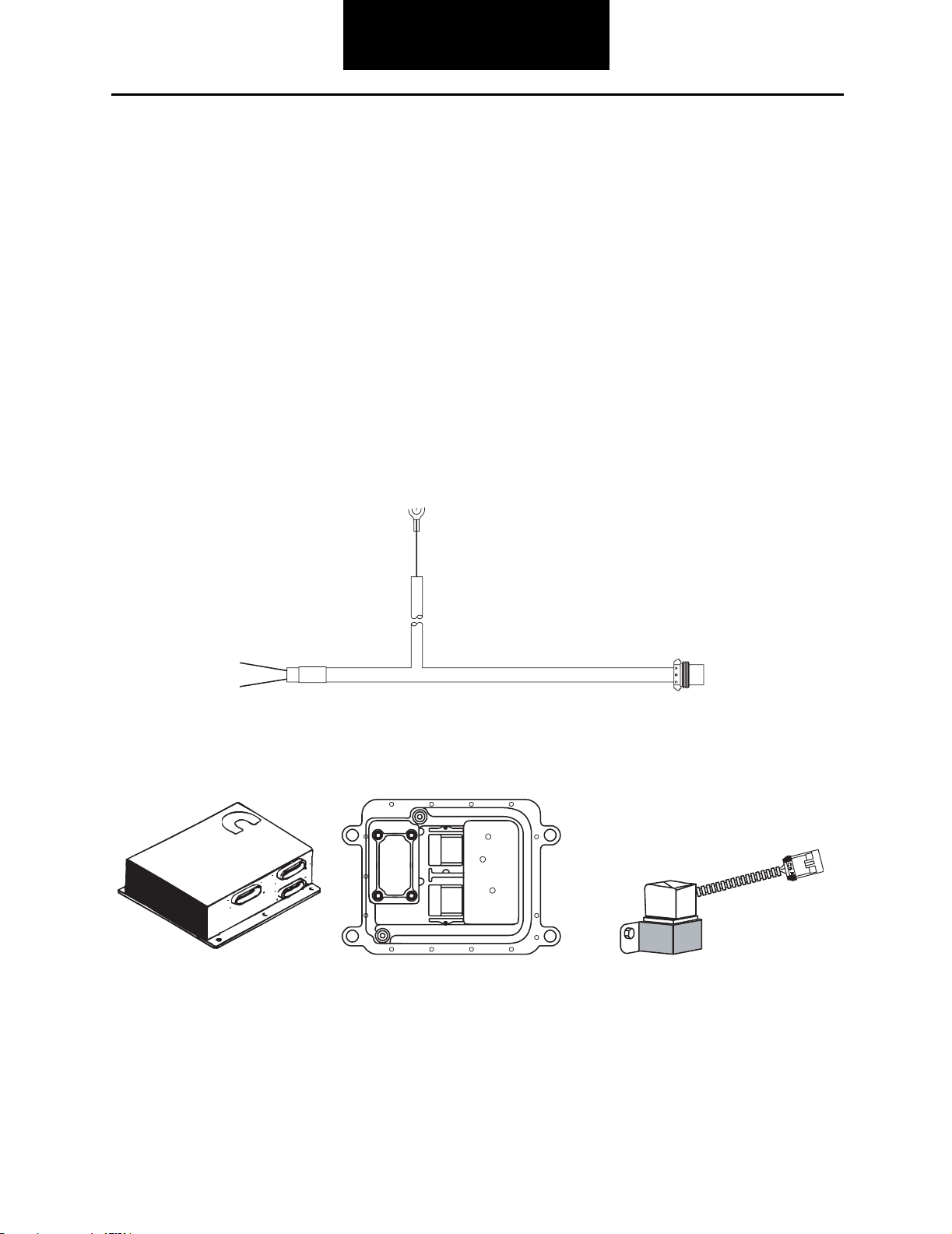
1
1. 10 AMP fuse
2. Typical vehicle interface
harness OEM supplied
3. DDEC III ECM OEM supplied
4. Top 2 solenoid valve
2-4
2
4
3
Page 24

Fault Code Procedures
Fault Code: 62 (SID:26,40,53-56,FMI: 3,4) DDEC III - Shift Solenoid or Lockout Solenoid
Step A Procedure Condition Action
1. Key off.
2. Disconnect three-way
connector from Top 2 solenoid.
3. Measure resistance between
Top 2 valve connector pins:
• A and B (red & blue wires)
•B and C (blue &
white wires)
Note: Some early Top 2 valves
are wired with all blue
wires.
If resistance is 14 to 34
ohms
If resistance is outside of
range
Go to Step B.
Replace Top 2 valve.
Go to Step V.
(SID:26,40,53-56,FMI:3,4)
Fault Code: 62
2-5
Page 25

Fault Code Procedures
Fault Code: 62 (SID:26,40,53-56,FMI:3,4)
DDEC III - Shift Solenoid or Lockout Solenoid, continued
Step B Procedure Condition Action
1. Measure resistance
between Top 2 valve
connector pin A (red
wire) and ground.
If the resistance is more
than 10K ohms or infinite
If the resistance is less
than 10K ohms
Go to Step C.
Replace the Top 2 valve. Go to
Step V.
2-6
Page 26

Fault Code Procedures
Fault Code: 62 (SID:26,40,53-56,FMI:3,4)
DDEC III - Shift Solenoid or Lockout Solenoid, continued
Step C Procedure Condition Action
1. Key off.
2. Measure voltage
between vehicle
interface harness
connector pin B and
ground.
If voltage is within 1 volt
of battery voltage
If voltage is outside of
range
Top 2 valve is OK, problem exists in
engine ECM or vehicle harness.
Repair according to vehicle OEM
recommendations. Go to Step V.
Top 2 valve is functioning properly,
problem exists in power supply.
Repair/replace as required. Go to
Step V.
(SID:26,40,53-56,FMI:3,4)
Fault Code: 62
Step V Procedure Condition Action
1. Key off.
2. Reconnect all connectors.
3. Key on.
4. Use Driving Technique to
attempt to reset the code (see
page 1-12).
5. Retrieve fault codes
(see page 1-8).
If no codes Test complete.
If code 62 appears Return to Step A to find error in
testing.
2-7
Page 27
Fault Isolation Procedures
Fault Code: 537, 536 (SID: 40, 51, FMI: 11) Cummins - Shift Solenoid or Lockout Solenoid
Overview
This is an active fault indicating an electrical problem in
the Top 2 shift or lockout solenoid circuit.
Detection
Key on. If active check engine light is on, Top 2 will not
function.
Fallback
Hold current solenoid state or gear until neutral is detected, then manual mode until system powers down.
Required Tools
• Basic Hand Tools
• Digital Volt/Ohm Meter
• Top 2 Troubleshooting Guide
Possible Causes
This fault can be caused by any of the following conditions:
• Electrical open or short in the shift solenoid circuit
• Damaged vehicle interface harness
• Faulty engine control module (ECM)
1
2
4
1. Typical vehicle interface 4. OEM Supplied
harness OEM supplied 5. Top 2 Solenoid valve
2. Cummins Celect Plus ECM
3. CAT ECM
3
5
2-8
Page 28

Fault Isolation Procedures
Fault Code: 537, 536 (SID: 40,51, FMI: 11) Cummins - Shift Solenoid or Lockout Solenoid
Step A Procedure Condition Action
1. Key off.
2. Disconnect three-way
connector from Top 2 solenoid.
Fault Code: 537, 536
(SID: 40,51, FMI: 11)
3. Measure resistance
between Top 2 valve
connector pins:
• A and B (red & blue wires)
• B and C (blue & white
wires)
Note: Some early Top 2 valves
are wired with all blue
wires.
If resistance is 14 to 34
ohms
If resistance is outside of
range
Go to Step B.
Replace Top 2 valve. Go to Step
V.
2-9
Page 29

Fault Isolation Procedures
Fault Code: 537, 536 (SID: 40,51, FMI: 11)
Cummins - Shift Solenoid or Lockout Solenoid, continued
Step B Procedure Condition Action
1. Measure the
resistance between
Top 2 valve connector
pin A (red wire) and
ground.
If resistance is more than
10K ohms or infinite
If resistance is less than
10K ohms
Go to Step C.
Replace Top 2 valve. Go to Step
V.
Step C Procedure Condition Action
1. Key off.
2. Disconnect battery positive (+)
cable.
3. Measure resistance
between vehicle
interface harness
connector pin B and
ground.
If resistance is 0 to .3
ohms
If resistance is outside of
range
Top 2 valve is functioning properly,
problem exists in engine ECM or
vehicle harness. Repair according
to OEM recommendations. Go to
Step V.
Faulty ground. Repair/replace
vehicle interface harness.
2-10
Page 30

Fault Isolation Procedures
Fault Code: 537, 536 (SID: 40,51, FMI: 11)
Cummins - Shift Solenoid or Lockout Solenoid, continued
Step V Procedure Condition Action
1. Key off.
2. Reconnect all connectors.
3. Key on.
4. Use Driving Technique to
attempt to reset the code (see
page 1-12).
5. Retrieve fault codes
(see page 1-8).
If no codes Test complete.
If code 537 or 536
appears
Return to Step A to find error in
testing.
Fault Code: 537, 536
(SID: 40,51, FMI: 11)
2-11
Page 31

Fault Isolation Procedures
Fault Code: 66,67 (SID: 40,51, FMI: 5,6) Caterpillar - Shift Solenoid or Lockout Solenoid
Overview
This is an active fault indicating an electrical problem in
the Top 2 shift or lockout solenoid circuit.
Detection
Hold current solenoid state or gear until neutral is detected, then manual mode until system powers down.
Fallback
Key on. If active check engine light is on, Top 2 will not
function.
Required Tools
• Basic Hand Tools
• Digital Volt/Ohm Meter
• Top 2 Troubleshooting Guide
Possible Causes
This fault can be caused by any of the following:
• Electrical open or short in the shift solenoid circuit (solenoid, wire harness, or connector)
• Damaged vehicle interface harness
• Faulty engine control module (ECM)
1
2
4
1. Typical vehicle interface 4. OEM Supplied
harness OEM supplied 5. Top 2 Solenoid valve
2. Cummins Celect Plus ECM
3. CAT ECM
3
5
2-12
Page 32

Fault Isolation Procedures
Fault Code: 66,67 (SID: 40,51, FMI: 5,6) Caterpillar - Shift Solenoid or Lockout Solenoid
Step A Procedure Condition Action
1. Key off.
2. Disconnect three way connector
from Top 2 solenoid.
3. Measure resistance
between Top 2 valve
connector pins:
• A and B (red & blue wires)
• B and C (blue and white
wires)
Note: Some early Top 2 valves
are wired with all blue
wires.
If resistance is 14 to 34
ohms
If resistance is outside of
range
Go to Step B.
Replace Top 2 valve. Go to Step
V.
(SID: 40,51, FMI 5,6)
Fault Code: 66,67
2-13
Page 33

Fault Isolation Procedures
Fault Code: 66,67 (SID: 40,51, FMI 5,6)
Caterpillar - Shift Solenoid or Lockout Solenoid, continued
Step B Procedure Condition Action
1. Measure the
resistance between
Top 2 valve connector
pin A (red wire) and
ground.
If resistance is more than
10K ohms or infinite
If resistance is less than
10K ohms
Go to Step C.
Replace Top 2 valve. Go to Step
V.
Step C Procedure Condition Action
1. Key off.
2. Disconnect battery positive (+)
cable.
3. Measure resistance
between vehicle
interface harness
connector pin B and
ground.
If resistance is 0 to .3
ohms
If resistance is outside of
range
Top 2 valve is functioning properly,
the problem exists in engine ECM or
vehicle harness. Repair according
to OEM recommendations. Go to
Step V.
Faulty ground. Repair/replace
vehicle interface harness.
2-14
Page 34

Fault Isolation Procedures
Fault Code: 66,67 (SID: 40,51, FMI 5,6)
Caterpillar - Shift Solenoid or Lockout Solenoid, continued
Step V Procedure Condition Action
1. Key off.
2. Reconnect all connectors.
3. Key on.
4. Use the Driving Technique to
attempt to reset the code (see
page 1-12).
5. Retrieve fault codes,
(see page 1-8).
If no codes Test complete.
If code 537 or 536
appears
Return to Step A to find error in
testing.
(SID: 40,51, FMI 5,6)
Fault Code: 66,67
2-15
Page 35

Fault Isolation Procedures
Fault Code: 44,43 (SID: 10,11, FMI: 3,4) MACK - Shift Solenoid or Lockout Solenoid
Overview
This is an active fault indicating an electrical problem in
the Top 2 shift or lockout solenoid circuit.
Detection
Key on. If active check engine light is on, Top 2 will not
function.
Fallback
Hold current solenoid state or gear until neutral is detected, then manual mode until system powers down.
Required Tools
• Basic Hand Tools
• Digital Volt/Ohm Meter
• Top 2 Troubleshooting Guide
Possible Causes
This fault can be caused by any of the following:
• Electrical open or short in the shift solenoid circuit (solenoid, wiring harness, or connector)
• Damaged vehicle interface harness
• Faulty engine control module (ECM)
• Faulty Mack VECU
• Mack 12V supply to Top 2 valve failed (Pin B)
2-16
1
2
4
1. Typical vehicle interface 4. OEM Supplied
harness OEM supplied 5. Top 2 Solenoid valve
2. Cummins Celect Plus ECM
3. CAT ECM
3
5
Page 36

Fault Isolation Procedures
Fault Code: 44,43 (SID: 10,11, FMI: 3,4) MACK - Shift Solenoid or Lockout Solenoid
Step A Procedure Condition Action
1. Key off.
2. Disconnect three-way
connector from Top 2 solenoid.
3. Measure resistance
between Top 2 valve
connector pins:
• A and B (red & blue wires)
• B and C (blue & white
wires)
Note: Some early Top 2 valves
are wired with all blue
wires.
If resistance is 14 to 34
ohms
If resistance is outside of
range
Go to Step B.
Replace Top 2 valve. Go to Step
V.
(SID: 10,11, FMI: 3,4)
Fault Code: 44,43
2-17
Page 37

Fault Isolation Procedures
Fault Code: 44,43 (SID: 10,11, FMI: 3,4)
MACK - Shift Solenoid or Lockout Solenoid, continued
Step B Procedure Condition Action
1. Measure resistance
between Top 2 valve
connector pin A (red
wire) and ground.
If resistance is more than
10K ohms or infinite
If resistance is less than
10K ohms
Go to Step C.
Replace Top 2 valve. Go to Step
V.
Step C Procedure Condition Action
1. Key off.
2. Disconnect battery positive (+)
cable.
3. Measure resistance
between vehicle
interface harness
connector pin B and
ground.
If resistance is 0 to .3
ohms
If voltage is outside of
range
Top 2 valve is functioning properly,
the problem exists in engine ECM or
vehicle harness. Repair according
to vehicle OEM recommendations.
Go to Step V.
Faulty ground. Repair / replace
vehicle interface harness.
2-18
Page 38

Fault Isolation Procedures
Fault Code: 44,43 (SID: 10,11, FMI: 3,4)
MACK - Shift Solenoid or Lockout Solenoid, continued
Step V Procedure Condition Action
1. Key off.
2. Reconnect all connectors.
3. Key on.
4. Use Driving Technique to
attempt to reset the code (see
page 1-12).
5. Retrieve fault codes
(see page 1-8).
If no codes Test complete.
If code 44 or 43 appears Return to Step A to find error in
testing.
(SID: 10,11, FMI: 3,4)
Fault Code: 44,43
2-19
Page 39

Fault Isolation Procedures
Fault Code: 62 (SID: 26,40,53-56, FMI: 7) DDEC III - Mechanical System Not Responding
Overview
This fault indicates the transmission failed to complete an
automatic Top 2 shift as commanded by the engine’s electronic control module (ECM).
Detection
The transmission will make three attempts for the Top 2
to shift. If it fails, the fault is set with check engine light.
Fallback
The transmission will return to manual mode shifting.
1
Required Tools
• Basic Hand Tools
• Digital Volt/Ohm Meter
• Top 2 Troubleshooting Guide
• Engine Manufacturer Scan Tool
Possible Causes
This fault can be caused by any of the following:
• Low air pressure
• Contaminated air supply
• Faulty Top 2 solenoid valve
• Faulty splitter cylinder
• Loose tone wheel
• Faulty/Contaminated Exhaust Breather
1. Top 2 solenoid valve
2. Air filter/regulator
3. Splitter cylinder
2-20
10 Speed
2
3
1. Top 2 solenoid valve
2. Air filter/regulator
3. Splitter cylinder
13 and 18 Speed
1
2
3
Page 40

Fault Isolation Procedures
(SID: 26,40,53-56, FMI: 7)
Fault Code: 62 (SID: 26,40,53-56, FMI: 7) DDEC III - Mechanical System Not Responding
Step A Procedure Condition Action
1. Operate the vehicle. Attempt to
perform HI to LO and LO to HI
split shifts using the splitter
button.
Note: For Convertible models go
directly to Step 2.
2. Confirm AUTO Mode
function is working
correctly.
Step B Procedure Condition Action
1. Key off.
2. Disconnect Top 2 valve air
supply line (S Port).*
If the transmission
performs split shifts in all
gears except AUTO Mode
If the transmission
consistently does not
perform split shifts
Go to Step B.
Perform Splitter System Test (see
page 3-15). Go to Step V.
Fault Code: 62
3. Connect a 100 psi air
gauge to the supply
line.
Air pressure 58 to 63 psi Go to Step C.
Air pressure not within
58 to 63 psi
18 Speed Shown
*See Schematic in Appendix for exact location.
Go to Step D.
2-21
Page 41

Fault Isolation Procedures
Fault Code: 62 (SID: 26,40,53-56, FMI: 7)
DDEC III - Mechanical System Not Responding, continued
Step C Procedure Condition Action
1. Inspect exhaust
breather on Top 2
valve for damage or
contamination.*
*If unsure breather is faulty, test drive vehicle with breather removed.
If exhaust breather is
restricted or Top 2
functions with breather
removed
If exhaust breather is
fuctioning properly
Replace breather. Go to Step V.
Go to Step E.
Step D Procedure Condition Action
1. Inspect the Top 2
valve air supply
fittings and line.
If the fittings and air lines
are fuctioning properly
If the fittings and air lines
are restricted or damaged
Replace air filter/regulator. Go to
Step V.
Repair as necessary. Go to Step V.
Step E Procedure Condition Action
1. Connect engine manufacturer
scan tool.
Note: MPSI Pro-Link Scan Tool
with Eaton cartridge may be
used on some engines.
2. Disconnect air line from P2 and
connect 100 psi air gauge to Top
2 valve P2 port. Leave P1 and
supply ports connected.
3. Remove P1 and plug for
Convertible.
4. Actuate Shift
Solenoid ON (Coil B).
Air pressure 58 to 63 psi Go to Step F.
Air pressure not within 58
to 63 psi
Replace Top 2 valve.
Go to Step V.
2-22
Page 42

Fault Isolation Procedures
Fault Code: 62 (SID: 26,40,53-56, FMI: 7)
DDEC III - Mechanical System Not Responding, continued
Step F Procedure Condition Action
1. Leaving Shift Solenoid ON.
Reconnect P1 port for
Convertible.
2. Listen for air leaking
at Top 2 exhaust
breather and
Roadranger valve.
Air leaks from one or
both
Air does not leak from
valve or breather
Step G Procedure Condition Action
1. Leaving 100 psi air gauge
connected to P2 port of the Top
2 valve.
2. Move splitter button forward.
Note: No action required for
Convertibles.
Replace Top 2 valve.
Go to Step V.
Go to Step G.
(SID: 26,40,53-56, FMI: 7)
Fault Code: 62
3. Using diagnostic tool
actuate Shift Solenoid
OFF and Lockout
Solenoid ON.
Air pressure gauge reads
0 psi
Air pressure reads above
0 psi
Go to Step H.
Replace Top 2 valve.
Go to Step V.
Step H Procedure Condition Action
1. Leave Shift Solenoid OFF and
Lockout Solenoid ON.
2. Leave splitter button forward.
Note: No action required for
Convertibles.
3. Listen for air leaking
from Top 2 breather.
Air leaks from breather Replace Top 2 valve.
Go to Step V.
Air does not leak from
breather
Go to Step I.
2-23
Page 43

Fault Isolation Procedures
Fault Code: 62 (SID: 26,40,53-56, FMI: 7)
DDEC III - Mechanical System Not Responding, continued
Step I Procedure Condition Action
1. Disconnect Top 2 valve 3-way
connector from vehicle harness.
2. Turn on ignition key.
3. Using MPSI Scan
Tool read the Active
Fault Codes.
Active Shift or Lockout
Solenoid Fault present
(see page 1-12).
No Active Fault set Engine ECU not programmed for
Go to Step V.
Top 2. Contact Engine OEM for
service. Go to Step V.
Step V Procedure Condition Action
1. Reconnect all air lines and
electrical connectors.
2. Start engine.
3. Allow air pressure to build to
governor cutoff.
4. Key off.
5. Listen for constant air leaks
under the following conditions:
Note: Skip the following
procedures for Convertibles
• Shift lever in neutral with
splitter button back.
2-24
• Shift lever in neutral with
splitter button forward.
• Shift lever in 7th/8th gear
position.
6. Perform test drive. If there are no constant
air leaks and test drive
confirms repair
If there are constant leaks
or test drive does not
confirm vehicle repair
Test complete.
Return to Step A to find error in
testing.
Page 44

Fault Isolation Procedures
Fault Code: 62 (SID: 26,40,53-56, FMI: 7)
DDEC III - Mechanical System Not Responding, continued
(SID: 26,40,53-56, FMI: 7)
Fault Code: 62
This page intentionally left blank
2-25
Page 45

Fault Isolation Procedures
Fault Code: 544 (PID: 191, FMI: 7) Cummins - Mechanical System Not Responding
Overview
This fault indicates the transmission failed to complete an
automatic Top 2 Shift as commanded by the engine’s
electronic control module (ECM).
Detection
The transmission will make three attempts for the Top 2
to shift. If it fails, the fault is set with check engine light.
Fallback
The transmission will return to manual mode shifting.
1
Required Tools
• Basic Hand Tools
• Digital Volt/Ohm Meter
• Top 2 Troubleshooting Guide
• Engine Manufacturer Scan Tool
Possible Causes
This fault code can be caused by any of the following:
• Low air pressure
• Contaminated air supply
• Faulty Top 2 solenoid valve
• Faulty splitter cylinder
• Loose tone wheel
• Faulty/Contaminated Exhaust Breather
• Cruise Switch
1. Top 2 solenoid valve
2. Air filter/regulator
3. Splitter cylinder
2-26
10 Speed
2
1
2
3
3
1. Top 2 solenoid valve
2. Air filter/regulator
3. Splitter cylinder
13 and 18 Speed
Page 46

Fault Isolation Procedures
Fault Code: 544 (PID: 191, FMI: 7) Cummins - Mechanical System Not Responding
Step A Procedure Condition Action
1. Operate the vehicle. Attempt to
perform HI to LO and LO to HI
split shifts using the splitter
button.
Note: For Convertible models go
directly to Step 2.
2. Confirm AUTO Mode
function is working
correctly.
If the transmission
performs split shifts in all
gears except AUTO Mode
Go to Step B.
(PID: 191, FMI: 7)
Fault Code: 544
If the transmission
consistently does not
perform split shifts
Perform Splitter System Test on
(see page 3-15). Go to Step V.
Step B Procedure Condition Action
1. Key off.
2. Disconnect Top 2 valve air
supply line (S Port).*
3. Connect a 100 psi air
gauge to the supply
line.
Air pressure 58 to 63 psi Go to Step C.
Air pressure not within
58 to 63 psi
Go to Step D.
18 Speed Shown
*See Schematic in Appendix for exact location.
2-27
Page 47

Fault Isolation Procedures
Fault Code: 544 (PID: 191, FMI: 7)
Cummins - Mechanical System Not Responding, continued
Step C Procedure Condition Action
1. Inspect exhaust
breather on Top 2
valve for damage or
contamination.*
*If unsure breather is faulty, test drive vehicle with breather removed.
If exhaust breather is
restricted or Top 2
functions with breather
removed
If exhaust breather is
functioning properly
Replace breather. Go to Step V.
Go to Step E.
Step D Procedure Condition Action
1. Inspect the Top 2
valve air supply
fittings and line.
If the fittings and air lines
are functioning properly
If the fittings and air lines
are restricted or damaged
Replace air filter/regulator.
Go to Step V.
Repair as necessary.
Go to Step V.
Step E Procedure Condition Action
1. Connect engine manufacturer
scan tool.
Note: MPSI Pro-Link Scan Tool
with Eaton cartridge may be
used on some engines.
2-28
2. Disconnect air line from P2 and
connect 100 psi air gauge to Top
2 valve P2 port. Leave P1 and
supply ports connected.
3. Remove P1 and plug for
Convertilbe.
4. Actuate Shift
Solenoid ON (Coil B).
Air pressure 58 to 63 psi Go to Step F.
Air pressure not within 58
to 63 psi
Replace Top 2 valve.
Go to Step V.
Page 48

Fault Isolation Procedures
Fault Code: 544 (PID: 191, FMI: 7)
Cummins - Mechanical System Not Responding, continued
Step F Procedure Condition Action
1. Leaving Shift Solenoid ON.
Reconnect P1 port for
Convetible.
2. Listen for air leaking
at Top 2 exhaust
breather and
Roadranger valve.
Air leaks from one or
both
Air does not leak from
valve or breather
Replace Top 2 valve.
Go to Step V.
Go to Step G.
Step G Procedure Condition Action
1. Leaving 100 psi air gauge
connected to P2 Port of the Top
2 valve.
2. Move splitter button forward.
Note: No action required for
Convertibles.
3. Using diagnostic tool
actuate Shift Solenoid
OFF and Lockout
Solenoid ON.
Air pressure gauge reads
0 psi
Air pressure reads above
0 psi
Go to Step H.
Replace Top 2 valve.
Go to Step V.
(PID: 191, FMI: 7)
Fault Code: 544
Step H Procedure Condition Action
1. Leave Shift Solenoid OFF and
Lockout Solenoid ON.
2. Leave splitter button forward.
Note: No action required for
Convertibles.
3. Listen for air leaking
from Top 2 breather.
Air leaks from breather Replace Top 2 valve.
Go to Step V.
Air does not leak from
breather
Go to Step I.
2-29
Page 49

Fault Isolation Procedures
Fault Code: 544 (PID: 191, FMI: 7)
Cummins - Mechanical System Not Responding, continued
Step I Procedure Condition Action
1. Disconnect Top 2 valve 3-way
connector from vehicle harness.
2. Turn on ignition key.
3. Using MPSI Scan
Tool read the Active
Fault Codes.
Active Shift or Lockout
Solenoid Fault present
(see page 1-12)
No Active Fault set Engine ECU not programmed for
Go to Step V.
Top 2. Contact Engine OEM for
service. Go to Step V.
Step V Procedure Condition Action
1. Reconnect all air lines and
electrical connectors.
2. Start engine.
3. Allow air pressure to build to
governor cutoff.
4. Key off.
5. Listen for constant air leaks
under the following conditions:
Note: Skip these procedures for
Convertibles
• Shift lever in neutral with
splitter button back.
2-30
• Shift lever in neutral with
splitter button forward.
• Shift lever in 7th/8th gear
position.
6. Perform test drive. If there are no constant
air leaks and test drive
confirms repair
If there are constant leaks
or test drive does not
confirm vehicle repair
Test complete.
Return to Step A to find error in
testing.
Page 50

Fault Isolation Procedures
Fault Code: 544 (PID: 191, FMI: 7)
Cummins - Mechanical System Not Responding, continued
(PID: 191, FMI: 7)
Fault Code: 544
This page intentionally left blank
2-31
Page 51

Fault Isolation Procedures
Fault Code: 68 (PID: 191, FMI:7) Caterpillar - Mechanical System Not Responding
Overview
This fault code indicates the transmission failed to complete an automatic Top 2 shift as commanded by the engine’s electronic control module (ECM).
Detection
The transmission will make three attempts for the Top 2
to shift. If it fails, the fault is set with check engine light.
Fallback
The transmission will return to manual mode shifting.
1
Required Tools
• Basic Hand Tools
• Digital Volt/Ohm Meter
• Top 2 Troubleshooting Guide
• Engine Manufacturer Scan Tool
Possible Causes
This fault can be caused by any of the following:
• Low air pressure
• Contaminated air supply
• Faulty Top 2 solenoid valve
• Faulty splitter cylinder
• Loose tone wheel
• Faulty/Contaminated Exhaust Breather
1. Top 2 solenoid valve
2. Air filter/regulator
3. Splitter cylinder
2-32
10 Speed
2
1
2
3
3
1. Top 2 solenoid valve
2. Air filter/regulator
3. Splitter cylinder
13 and 18 Speed
Page 52

Fault Isolation Procedures
Fault Code: 68 (PID: 191, FMI: 7) Caterpillar - Mechanical System Not Responding
Step A Procedure Condition Action
1. Operate the vehicle. Attempt to
perform HI to LO and LO to HI
split shifts using the splitter
button.
Note: For Convertible models go
directly to Step 2.
2. Confirm AUTO Mode
function is working
correctly.
If the transmission
performs split shifts in all
gears except AUTO Mode
If the transmission
consistently does not
perform split shifts
Go to Step B.
Perform Splitter System Test on
(see page 3-15). Go to Step V.
Step B Procedure Condition Action
1. Key off.
2. Disconnect Top 2 valve air
supply line (S Port).*
3. Connect a 100 psi air
gauge to the supply
line.
Air pressure 58 to 63 psi Go to Step C.
Air pressure not within
58 to 63 psi
Go to Step D.
(PID: 191, FMI: 7)
Fault Code: 68
18 Speed Shown
*See Schematic in Appendix for exact location.
2-33
Page 53

Fault Isolation Procedures
Fault Code: 68 (PID: 191, FMI: 7)
Caterpillar - Mechanical System Not Responding, continued
Step C Procedure Condition Action
1. Inspect exhaust
breather on Top 2
valve for damage or
contamination.*
*If unsure breather is faulty, test drive vehicle with breather removed.
If exhaust breather is
restricted or Top 2
functions with breather
removed
If exhaust breather is
functioning properly
Replace breather. Go to Step V.
Go to Step E.
Step D Procedure Condition Action
1. Inspect the Top 2
valve air supply
fittings and line.
If the fittings and air lines
are functioning properly
If the fittings and air lines
are restricted or damaged
Replace air filter/regulator. Go to
Step V.
Repair as necessary. Go to Step V.
Step E Procedure Condition Action
1. Connect engine manufacturer
scan tool.
Note: MPSI Pro-Link Scan Tool
with Eaton cartridge may be
used on some engines.
2-34
2. Disconnect air line from P2 and
connect 100 psi air gauge to Top
2 valve P2 port. Leave P1 and
supply ports connected.
3. Remove P1 and plug for
Convertible.
4. Actuate Shift
Solenoid ON (Coil B).
Air pressure 58 to 63 psi Go to Step F.
Air pressure not within 58
to 63 psi
Replace Top 2 valve.
Go to Step V.
Page 54

Fault Isolation Procedures
Fault Code: 68 (PID: 191, FMI: 7)
Caterpillar - Mechanical System Not Responding, continued
Step F Procedure Condition Action
1. Leaving Shift Solenoid ON.
Reconnect P1 port for
Convertible.
2. Listen for air leaking
at Top 2 exhaust
breather and
Roadranger valve.
Air leaks from one or
both
Air does not leak from
valve or breather
Replace Top 2 valve.
Go to Step V.
Go to Step G.
Step G Procedure Condition Action
1. Leaving 100 psi air gauge
connected to P2 Port of the Top
2 valve.
2. Move splitter button forward.
Note: No action required for
Convertibles.
3. Using diagnostic tool
actuate Shift Solenoid
OFF and Lockout
Solenoid ON.
Air pressure gauge reads
0 psi
Air pressure reads above
0 psi
Go to Step H.
Replace Top 2 valve.
Go to Step V.
(PID: 191, FMI: 7)
Fault Code: 68
Step H Procedure Condition Action
1. Leave Shift Solenoid OFF and
Lockout Solenoid ON.
2. Leave splitter button forward.
Note: No action required for
Convertibles.
3. Listen for air leaking
from Top 2 breather.
Air leaks from breather Replace Top 2 valve.
Go to Step V.
Air does not leak from
breather
Go to Step I.
2-35
Page 55

Fault Isolation Procedures
Fault Code: 68 (PID: 191, FMI: 7)
Caterpillar - Mechanical System Not Responding, continued
Step I Procedure Condition Action
1. Disconnect Top 2 valve 3-way
connector from vehicle harness.
2. Turn on ignition key.
3. Using MPSI Scan
Tool read the Active
Fault Codes.
Active Shift or Lockout
Solenoid Fault present
(see page 1-12)
No Active Fault set Engine ECU not programmed for
Go to Step V.
Top 2. Contact Engine OEM for
service. Go to Step V.
Step V Procedure Condition Action
1. Reconnect all air lines and
electrical connectors.
2. Start engine.
3. Allow air pressure to build to
governor cutoff.
4. Key off.
5. Listen for constant air leaks
under the following conditions:
Note: Skip these procedures for
Convertibles
• Shift lever in neutral with
splitter button back.
2-36
• Shift lever in neutral with
splitter button forward.
• Shift lever in 7th/8th gear
position.
6. Perform test drive. If there are no constant
air leaks and test drive
confirms repair
If there are constant leaks
or test drive does not
confirm vehicle repair
Test complete.
Return to Step A to find error in
testing.
Page 56

Fault Isolation Procedures
Fault Code: 68 (PID: 191, FMI: 7)
Caterpillar - Mechanical System Not Responding, continued
(PID: 191, FMI: 7)
Fault Code: 68
This page intentionally left blank
2-37
Page 57

Fault Isolation Procedures
Fault Code: 38 (PID: S32, FMI: 7) MACK - Mechanical System Not Responding
Overview
This fault indicates the transmission failed to complete an
automatic Top 2 shift as commanded by the engines electronic control module (ECM).
Detection
The transmission will make three attempts for the Top 2
to shift. If it fails, the fault is set with check engine light.
Fallback
The transmission will return to manual mode shifting.
1
Required Tools
• Basic Hand Tools
• Digital Volt/Ohm Meter
• Top 2 Troubleshooting Guide
• Engine Manufacturer Scan Tool
Possible Causes
This fault can be caused by any of the following:
• Low air pressure
• Contaminated air supply
• Faulty Top 2 solenoid valve
• Faulty splitter cylinder
• Loose tone wheel
• Faulty/Contaminated Exhaust Breather
1. Top 2 solenoid valve
2. Air filter/regulator
3. Splitter cylinder
10 Speed
2
1
2
3
3
1. Top 2 solenoid valve
2. Air filter/regulator
3. Splitter cylinder
13 and 18 Speed
2-38
Page 58

Fault Isolation Procedures
Fault Code: 38 (PID: S32, FMI: 7) MACK - Mechanical System Not Responding
Step A Procedure Condition Action
1. Operate the vehicle. Attempt to
perform HI to LO and LO to HI
split shifts using the splitter
button.
Note: For Convertible models
go directly to Step 2.
2. Confirm AUTO Mode
function is working
correctly.
Step B Procedure Condition Action
1. Key off.
2. Disconnect Top 2 valve air
supply line (S Port).*
If the transmission
performs split shifts in all
gears except AUTO Mode
If the transmission
consistently does not
perform split shifts
Go to Step B.
Perform Splitter System Test on
(see page 3-15). Go to Step V.
(PID: S32, FMI: 7)
Fault Code: 38
3. Connect a 100 psi air
gauge to the supply
line.
Air pressure 58 to 63 psi Go to Step C.
Air pressure not within
58 to 63 psi
18 Speed Shown
*See Schematic in Appendix for exact location.
Go to Step D.
2-39
Page 59

Fault Isolation Procedures
Fault Code: 38 (PID: S32, FMI: 7)
MACK - Mechanical System Not Responding, continued
Step C Procedure Condition Action
1. Inspect exhaust
breather on Top 2
valve for damage or
contamination.*
*If unsure breather is faulty, test drive vehicle with breather removed.
If exhaust breather is
restricted or Top 2
functions with breather
removed
If exhaust breather is
functioning properly
Replace breather. Go to Step V.
Go to Step E.
Step D Procedure Condition Action
1. Inspect the Top 2
valve air supply
fittings and line.
If the fittings and air lines
are functioning properly
If the fittings and air lines
are restricted or damaged
Replace air filter/regulator. Go to
Step V.
Repair as necessary.
Go to Step V.
Step E Procedure Condition Action
1. Connect engine manufacturer
scan tool.
Note: MPSI Pro-Link Scan Tool
with Eaton cartridge may be
used on some engines.
2-40
2. Disconnect air line from P2 and
connect 100 psi air gauge to Top
2 valve P2 port. Leave P1 and
supply ports connected.
3. Remove P1 and plug for
Convertible.
4. Actuate Shift
Solenoid ON (Coil B).
Air pressure 58 to 63 psi Go to Step F.
Air pressure not within 58
to 63 psi
Replace Top 2 valve.
Go to Step V.
Page 60

Fault Isolation Procedures
Fault Code: 38 (PID: S32, FMI: 7)
MACK - Mechanical System Not Responding, continued
Step F Procedure Condition Action
1. Leaving Shift Solenoid ON.
Reconnect P1 for Convertible.
(PID: S32, FMI: 7)
Fault Code: 38
2. Listen for air leaking
at Top 2 exhaust
breather and
Roadranger valve.
Air leaks from one or
both
Air does not leak from
valve or breather
Replace Top 2 valve.
Go to Step V.
Go to Step G.
Step G Procedure Condition Action
1. Leaving 100 psi air gauge
connected to P2 Port of the
Top 2 valve.
2. Move splitter button forward.
Note: No action required for
Convertibles.
3. Using diagnostic tool
actuate Shift Solenoid
OFF and Lockout
Solenoid ON.
Air pressure gauge reads
0 psi
Air pressure reads above
0 psi
Go to Step H.
Replace Top 2 valve.
Go to Step V.
Step H Procedure Condition Action
1. Leave Shift Solenoid OFF and
Lockout Solenoid ON.
2. Leave splitter button forward.
Note: No action required for
Convertibles.
3. Listen for air leaking
from Top 2 breather.
Air leaks from breather Replace Top 2 valve.
Go to Step V.
Air does not leak from
breather
Go to Step I.
2-41
Page 61

Fault Isolation Procedures
Fault Code: 38 (PID: S32, FMI: 7)
MACK - Mechanical System Not Responding, continued
Step I Procedure Condition Action
1. Disconnect Top 2 valve 3-way
connector from vehicle harness.
2. Turn on ignition key.
3. Using MPSI Scan
Tool read the Active
Fault Codes.
Active Shift or Lockout
Solenoid Fault present
(see page 1-12)
No Active Fault set Engine ECU not programmed for
Go to Step V.
Top 2. Contact Engine OEM for
service. Go to Step V.
Step V Procedure Condition Action
1. Reconnect all air lines and
electrical connectors.
2. Start engine.
3. Allow air pressure to build to
governor cutoff.
4. Key off.
5. Listen for constant air leaks
under the following conditions:
Note: Skip these procedures for
Convertibles.
• Shift lever in neutral with
splitter button back.
2-42
• Shift lever in neutral with
splitter button forward.
• Shift lever in 7th/8th gear
position.
6. Perform test drive. If there are no constant
air leaks and test drive
confirms repair
If there are constant leaks
or test drive does not
confirm vehicle repair
Test complete.
Return to Step A to find error in
testing.
Page 62

Symptom Procedures
Symptom Driven Diagnostics Table
If there are no fault codes present (active or inactive), it may be necessary to determine the cause of the problem on symptoms
exhibited by the vehicle. Locate the symptom that best describes the problem in the index below and perform the necessary fault
isolation procedure. All procedures can be located inside this troubleshooting guide.
Table 1
Symptom Isolation Procedure
Transmission has an air leak Air Leak Check - 10 Speed Only
Air Leak Check - 13 and 18 Speed Only
Diagnostics Table
Symptom Driven
Splitter shift is not satisfactory
(slow, grinding, does not complete)
System attempts Top 2 shift does not complete.
All other splitter shifts satisfactory.
Top 2 does not function. No fault set. Engine Programming/Cruise Control, refer to OEM Diagnostics
Splitter System Test
Mechanical System Not Responding Test
DDEC III, Cummins, CAT, and MACK
3-1
Page 63

Air Leak Test
Fault Isolation Procedures
Overview
This symptom-driven test is performed if the transmission has
an air leak and there are no Active or Inactive fault codes.
Detection
There is no detection process specifically for a transmission air
leak. However, failures of this type are generally detected by
the transmission or driver as some other type of fault code or
symptom.
Fallback
There is no fallback mode for a transmission air leak, however,
it may effect other vehicle systems.
Required Tools
• Basic Hand Tools
• Troubleshooting Guide
Possible Causes
This symptom can be caused by any of the following:
• Contaminated Air
• Range Valve
• Splitter Valve
• Air Filter/Regulator
• Range Piston / O-ring
3-2
Air filter / regulator
Splitter system
Page 64

Symptom Procedures
Air Leak Check - T2 Convertible Model Only
Step A Procedure Condition Action
1. Start engine.
2. Allow air pressure to build to
governor cutoff.
3. Place transmission in neutral
and range lever down.
4. Key off.
5. Listen for constant
leaks.
If there are no constant air
leaks
If air leaks from fittings or
lines at:
• Slave valve
• Air filter/regulator
• Splitter cylinder supply
line
• Top 2 valve supply line
If air leaks at the
Roadranger valve
If air leaks at the splitter
cylinder cover exhaust
port
If air leaks at the
transmission breather
If air leaks at the Top 2
valve breather
If air leaks at the slave
valve
Go to Step B.
Repair fittings or lines as required.
Repeat this step.
Convertible Model Only
Air Leak Check - T2
Repair or replace the Roadranger
valve as required. Repeat this step.
Replace splitter cover. If problem
persists, repair splitter piston/
cylinder. Repeat this step.
Go to Step D.
Replace Top 2 valve. Repeat this
step.
Replace slave valve. Repeat this
step.
3-3
Page 65

Symptom Procedures
Air Leak Check - T2 Convertible Model Only, continued
Step B Procedure Condition Action
1. Use MPSI tool cycle valve Top 2.
Note: High split - no action
required.
2. Listen for constant air
leaks.
If there are no constant air
leaks
If air leaks from fittings or
lines at:
• Top 2 ports P1 or P2
• Splitter cylinder signal line
If air leaks at Top 2 valve
exhaust port
If air leaks at the splitter
cylinder cover exhaust
port
If air leaks at transmission
breather
Go to Step C.
Repair fittings or lines as
required. Repeat this step.
Replace Top 2 valve. Repeat this
step.
Replace splitter insert valve.
Repeat this step.
Repair splitter yoke bar O-rings.
Repeat this step.
Step C Procedure Condition Action
1. Move range up.
2. Listen for constant air
leaks.
If there are no constant air
leaks
Test complete.
If air leaks at range
actuator valve exhaust
port
If air leaks from LO range
insert valve
If air leaks from HI range
insert valve
Replace range actuator valve.
Repeat this step.
Replace LO range insert valve.
Repeat this step.
Replace HI range insert valve.
Repeat this step.
Step D Procedure Condition Action
1. Move range down.
2. Listen for constant air
leaks.
3-4
If the air leak continues or
is present at transmission
breather
If the air leak stops Test complete.
Repair or replace the range bar
O-rings as required. Go to Step V.
Page 66

Symptom Procedures
Air Leak Check - T2 Convertible Model Only, continued
Step V Procedure Condition Action
1. Start engine.
2. Allow air pressure to build to
governor cutoff.
3. Key off
4. Listen for constant air
leaks under the
following conditions:
• Shift lever in neutral with
range button up.
• Shift lever in neutral with
range button down. MPSItrigger down.
• Shift lever in 7th/8th gear
position.
If there are no constant air
leaks
If there are constant air
leaks
Test complete.
Convertible Model Only
Air Leak Check - T2
Return to Step A to find error in
testing.
3-5
Page 67

Fault Isolation Procedures
Air Leak Test
Overview
This symptom-driven test is performed if the transmission has an air leak and there are no Active or Inactive fault
codes.
Detection
Required Tools
• Basic Hand Tools
• Troubleshooting Guide
There is no detection process specifically for a transmission air leak. However, failures of this type are generally
detected by the transmission or driver as some other type
of fault code or symptom.
Fallback
There is no fallback mode for a transmission air leak, however, it may effect other vehicle systems.
Possible Causes
This symptom can be caused by any of the following:
• Contaminated Air
• Range Valve
• Splitter Valve
• Air Filter/Regulator
• Range Piston / O-ring
3-6
Air filter / regulator
Page 68

Air Leak Check- 10 Speed Only
Symptom Procedures
Air Leak Check - 10 Speed
Step A Procedure Condition Action
1. Start engine.
2. Allow air pressure to build to
governor cutoff.
3. Place transmission in neutral
and move splitter button back.
4. Key off.
5. Listen for constant
leaks.
If there are no constant air
leaks
If air leaks from fittings or
lines at:
• Range actuator valve
• Air filter/regulator
• Splitter cylinder supply
line
• Top 2 valve supply line
If air leaks at the
Roadranger valve
Go to Step B.
Repair fittings or lines as required.
Repeat this step.
Repair or replace the Roadranger
valve as required. Repeat this step.
Only
If air leaks at the splitter
cylinder cover exhaust
port
If air leaks at the range
actuator valve exhaust
port
If air leaks at the LO range
insert valve
If air leaks at the
transmission breather
If air leaks at the HI range
insert valve
Replace splitter cover. If problem
persists, repair splitter piston/
cylinder. Repeat this step.
Replace the range actuator valve.
Repeat this step.
Replace the LO range insert valve.
Repeat this step.
Go to Step D.
Go to Step E.
3-7
Page 69

Symptom Procedures
Air Leak Check- 10 Speed Only, continued
Step B Procedure Condition Action
1. Move splitter button forward.
2. Listen for constant air
leaks.
If there are no constant air
leaks
If air leaks from fittings or
lines at:
• Top 2 ports P1 or P2
• Splitter cylinder signal line
If air leaks at Top 2 valve
exhaust port
If air leaks at the splitter
cylinder cover exhaust
port
Go to Step C.
Repair fittings or lines as
required. Repeat this step.
Replace Top 2 valve. Repeat this
step.
Replace splitter insert valve.
Repeat this step.
Step C Procedure Condition Action
1. Move shift lever to 7th/8th gear
position.
2. Listen for constant air
leaks.
If there are no constant air
leaks
If air leaks at range
actuator valve exhaust
port
Test complete.
Replace range actuator valve.
Repeat this step.
If air leaks from LO range
insert valve
If air leaks from HI range
insert valve
Replace LO range insert valve.
Repeat this step.
Replace HI range insert valve.
Repeat this step.
Step D Procedure Condition Action
1. Move shift lever to 7th/8th gear
position.
2. Listen for constant air
leaks.
3-8
If the air leak continues Repair or replace the splitter bar
O-rings as required. Go to Step V.
If the air leak stops Repair or replace the range bar
O-rings as required. Go to Step V.
Page 70

Symptom Procedures
Air Leak Check- 10 Speed Only, continued
Step E Procedure Condition Action
1. Move shift lever to 7th/8th gear
position.
2. Listen for constant air
leaks.
Step V Procedure Condition Action
1. Start engine.
2. Allow air pressure to build to
governor cutoff.
3. Key off
4. Listen for constant air
leaks under the
following conditions:
If the air leak changes to
the LO range insert valve
If the air leak stops or
continues from the HI
range insert valve
If there are no constant air
leaks
Repair the range cylinder and
piston as required. Go to Step V.
Replace range insert valves. Go to
Step V.
Test complete.
Air Leak Check - 10 Speed
Only
• Shift lever in neutral with
splitter button back.
• Shift lever in neutral with
splitter button forward.
• Shift lever in 7th/8th gear
position.
If there are constant air
leaks
Return to Step A to find error in
testing.
3-9
Page 71

Fault Isolation Procedures
Air Leak Test
Overview
This symptom-driven test is performed if the transmission has an air leak and there are no Active or Inactive fault
codes.
Detection
Required Tools
• Basic Hand Tools
• Troubleshooting Guide
There is no detection process specifically for a transmission air leak. However, failures of this type are generally
detected by the transmission or driver as some other type
of fault code or symptom.
Fallback
There is no fallback mode for a transmission air leak, however, it may effect other vehicle systems.
Possible Causes
This symptom can be caused by any of the following:
• Contaminated Air
• Range Valve
• Splitter Valve
• Air Filter/Regulator
• Range Piston / O-ring
3-10
Air filter / regulator
Splitter system
Page 72

Symptom Procedures
Air Leak Check - 13 and 18 Speed Only
Step A Procedure Condition Action
1. Start engine.
2. Allow air pressure to build to
governor cutoff.
3. Place transmission in neutral
and move splitter button back.
4. Move range lever down.
5. Key off.
6. Listen for constant air
leaks.
If there are no constant air
leaks
If air leaks from fittings or
lines at:
• Range actuator valve
• Air filter/regulator
• Splitter cylinder supply
line
• Top 2 valve supply line
If air leaks at the
Roadranger valve
If air leaks at the splitter
cylinder cover exhaust
port
Air Leak Check - 13 and 18
Speed Only
Go to Step B.
Repair fittings or lines as
required. Repeat this step.
Repair or replace the Roadranger
valve as required. Repeat this step.
Replace splitter cover. If problem
persists, repair splitter piston/
cylinder. Repeat this step.
If air leaks at the slave
valve
If air leaks at the
transmission breather
Replace the slave valve. Repeat
this step.
Go to Step D.
3-11
Page 73

Symptom Procedures
Air Leak Check - 13 and 18 Speed Only, continued
Step B Procedure Condition Action
1. Move splitter button forward.
2. Listen for constant air
leaks.
If there are no constant air
leaks
If air leaks from fittings or
lines at:
• Top 2 ports P1 or P2
• Splitter cylinder signal line
If air leaks at Top 2 valve
exhaust port
If air leaks at the splitter
cylinder cover exhaust
port
Go to Step C.
Repair fittings or lines as
required. Repeat this step.
Replace Top 2 valve. Repeat this
step.
Replace splitter insert valve.
Repeat this step.
Step C Procedure Condition Action
1. Move shift lever up.
2. Listen for constant air
leaks.
If there are no constant air
leaks
If air leaks at slave valve. Replace slave valve. Repeat this
Test complete.
step.
Step D Procedure Condition Action
1. Move shift lever up.
2. Listen for constant air
leaks.
3-12
If the air leak continues Repair or replace the splitter bar
O-rings as required. Go to Step V.
If the air leak stops Repair or replace the range bar O-
rings as required. Go to Step V.
Page 74

Symptom Procedures
Air Leak Check - 13 and 18 Speed Only, continued
Step V Procedure Condition Action
1. Start engine.
2. Allow air pressure to build to
governor cutoff.
3. Key off.
4. Listen for constant air
leaks under the
following conditions:
• Shift lever in neutral with
splitter button back.
• Shift lever in neutral with
splitter button forward.
If there are no constant air
leaks
Test complete.
Air Leak Check - 13 and 18
Speed Only
If there are constant air
leaks
Return to Step A to find error in
testing.
3-13
Page 75

Fault Isolation Procedures
Splitter System Test
Overview
This symptom-driven test is completed if the transmission does not perform Splitter Shifts, and there are no
active or inactive fault codes.
Detection
The failure is observed by the driver when operating the
vehicle. To observe this failure, operate the vehicle and
make several shifts up and down across the Splitter.
Fallback
There is no fallback for this symptom.
Required Tools
• Basic Hand Tools
• 0-100 PSI Air Pressure Gauges
• Troubleshooting Guide
Possible Causes
This symptom can be caused by any of the following:
• Low Air Pressure
• Contaminated Air Supply
• Air Leak
• Splitter Valve
• Splitter Actuator / Cylinder / Piston / Yoke
3-14
Air filter / regulator
Splitter system
Page 76

Symptom Procedures
Splitter System Test
Step A Procedure Condition Action
1. Key off.
2. Place transmission in neutral.
Move splitter button back.
3. Locate the signal line from the
Top 2 P2 port valve to the
splitter cylinder. Tee a 0-100 PSI
air pressure gauge into the line
at the splitter cylinder cover.
4. Move the splitter
button forward and
back. Observe the
pressure gauge.
If the pressure rapidly rises to
regulated pressure when the button
is forward and
Pressure rapidly
decreases when the
button is back
If the pressure does not
reach regulated pressure
or pressure does not
change rapidly
Go to Step E.
Splitter System Test
Go to Step B.
3-15
Page 77

Symptom Procedures
Splitter System Test, continued
Step B Procedure Condition Action
1. Remove gauge from Top 2 valve
signal line.
2. Locate the signal line from the
Roadranger valve to the Top 2
valve P1 port. Tee the pressure
gauge into the signal line at the
Top 2 valve.
3. Move the splitter
button forward and
back. Observe the
pressure gauge.
If the pressures rapidly rises to
regulated pressure when the button
is forward and
Pressure rapidly
decreases when the
button is back
If the pressure does not
reach regulated pressure
or pressure does not
change rapidly
Go to Step C.
Go to Step D.
Step C Procedure Condition Action
3-16
1. Inspect fittings and air lines at
port P1 and P2 or the Top valve.
2. Inspect signal line
fittings and air line
between Top 2 valve
and splitter cylinder.
If the fittings and air lines
are functioning properly
If the fittings and air lines
are restricted
Replace Top 2 valve. Go to Step
V.
Repair or replace as necessary. Go
to Step V.
Page 78

Symptom Procedures
Splitter System Test, continued
Step D Procedure Condition Action
1. Inspect fittings and air
lines between the:
• Top 2 valve and
Roadranger valve
• Roadranger valve, range
actuator valve, and air
filter/regulator
If the fittings and air lines
are functioning properly
If the fittings and air lines
are functioning properly
Replace Roadranger valve. Go to
Step V.
Repair as necessary. Go to Step V.
Step E Procedure Condition Action
1. Locate the supply line between
the splitter cylinder and air filter/
regulator. Tee a 0-100 PSI air
gauge into the line at the splitter
cylinder.
2. Observe the pressure
gauge.
If the pressure is 55 to 65
PSI
If the pressure is not 55 to
65 PSI
Go to Step G.
Go to Step F.
Splitter System Test
Step F Procedure Condition Action
1. Inspect supply fittings and air
lines between the splitter
cylinder and the air filter/
regulator.
If the fittings and air lines
are functioning properly
If the fittings and air lines
are restricted
Replace air filter/regulator. Go to
Step V.
Repair as necessary. Go to Step V.
3-17
Page 79

Symptom Procedures
Splitter System Test, continued
Step G Procedure Condition Action
1. Hold the spool valve
down.
Note: Use a small screwdriver
through the signal line
opening.
10 Speed Only
Note: Blow shop air into signal
line opening with a rubber
tip air gun.
If air does not exhaust when the
insert valve is pushed in and
Air briefly exhaust when
the insert valve is let out
If air does not exhaust as
indicated above
If air briefly exhausts
when shop air is applied
Go to Step I.
Go to Step H.
Go to Step I.
13 and 18 Speed Only
Note: Spool Valve Cylinder
Only: Through the signal
line opening use a small
screwdriver to push in the
spool valve. Valve travels
approximately 1/4 inch.
Air does not exhaust when
shop air is applied
If splitter shifts Replace spool valve. Go to Step V.
If splitter does not shift Go to Step J.
Go to Step H.
3-18
Page 80

Symptom Procedures
Splitter System Test, continued
Step H Procedure Condition Action
1. Inspect the exhaust port and
insert valve for contamination.
If exhaust port and insert
valves are functioning
properly
If contamination is found Repair or replace as needed. Go to
Replace the insert valve. Go to
Step V.
Step V.
Step I Procedure Condition Action
1. Remove the splitter cylinder
cover.
2. Inspect gasket. If the gasket is installed
correctly
If the gasket is not
installed correctly
Remove the auxiliary section and
repair as required. Go to Step V.
Repair as required. Go to Step V.
Step J Procedure Condition Action
1. Spool Valve Cylinder Only:
Remove exhaust breather on
cylinder top.
2. Push in the spool valve
with a small
screwdriver through
the signal line.
If splitter shifts Replace breather. Go to Step V.
Splitter System Test
If splitter does not shift Replace spool valve. Go to Step
V.
3-19
Page 81

Symptom Procedures
Splitter System Test, continued
Step V Procedure Condition Action
1. Move the splitter
button forward and
back. Observe the
pressure gauge.
If the pressure rapidly rises to
regulate pressure when the button
is forward and
Pressure rapidly
decreases when the
button is back
If the pressure does not
reach regulated pressure
or pressure does not
change rapidly
Test complete.
Go to Step B.
3-20
Page 82

Service Information
Service Information
This appendix section provides helpful background information on the Top 2 system.
Major topics:
• 9 speed convertible overview
• 10 speed overview
• 13 speed overview
• 18 speed overview
• Splitter cylinder operation - 10 speed only (old design)
• Splitter cylinder insert valve operation -10 speed only (old design)
• Splitter cylinder operation - 10 speed only (latest design)
• Splitter cylinder spool valve operation - 10 speed only (latest design)
• Splitter cylinder - 13 and 18 speed (old design)
• Insert valve - 13 and 18 speed (old design)
• Splitter cylinder - 13 and 18 speed only (latest design)
• Spool valve - 13 and 18 speed (latest design)
• Suggested test fixtures
Service Information
A-1
Page 83

Service Information
Top 2 System Overview - 9 Speed Convertible Only
Here is a schematic showing the components, air connectors, and air flow between the Top 2 Convertible components under
different gears.
l
A-2
Lock High
Except During
Top 2 Function
Page 84

Service Information
Top 2 System Overview - 10 Speed Only
The Eaton Fuller Top 2 is an add-on system to the Super 10 heavy-duty transmission. By itself, the Super 10 is a manually operated
transmission. When equipped with the Top 2 system; however, the Super 10 provides automatic shifting functions between the
top two gears.
The following figure highlights the components and features of the Top 2 system.
HI
4
LO
R
R
2
1
8
7
3
6
5
3
Top 2 System Overview
2
4
5
1
1. Range actuator valve - automatically activate LO and HI range
2. Top 2 solenoid valve - automatically shifts between the Top 2 gears
3. Roadranger valve - shifts transmission to the six gear positions
4. Range cylinder - shifts transmission between LO and HI range
5. Air filter/regulator
6. Splitter cylinder - shifts transmission between odd/even numbered
gear positions
6
A-3
Page 85

Service Information
Top 2 System Overview - 10 Speed Only (continued)
Here is a schematic showing the components, air connectors, and air flow between the Top 2 components under different gears.
A-4
Page 86

Service Information
Top 2 System Overview - 13 Speed Only
The Eaton Fuller Top 2 is an add-on system to the Super 13 heavy duty transmission. By itself, the Super 13 is a manually operated
transmission. When equipped with the Top 2 system; however, the Super 13 provides automatic shifting functions between the
top two gears.
The following figure highlights the components and features of the Top 2 system.
3
2
Top 2 System Overview
1
1. Slave Valve - directs air to the range cylinder
2. Top 2 solenoid valve - automatically shifts between the Top 2 gears
3. Roadranger valve - shifts transmission to the six gear positons
4. Range cylinder - shifts transmission between LO and HI range
5. Air Filter/ regulator
6. Splitter cylinder - shifts transmission between odd/even numbered
gear positions
4
5
6
A-5
Page 87

Service Information
Top 2 System Overview - 13 Speed Only (continued)
Here is a schematic showing the components, air connectors, and air flow between the Top 2 components under different gears.
A-6
Page 88

Service Information
Top 2 System Overview - 18 Speed Only
The Eaton Fuller Top 2 is an add-on system to the Super 18 heavy-duty transmission. By itself, the Super 18 is a manually operated
transmission. When equipped with the Top 2 system; however, the Super 18 provides automatic shifting functions between top
two gears.
The following figure highlights the components and features of the Top 2 System.
3
2
4
Top 2 System Overview
1
1. Slave valve - directs air to the range cylinder
2. Top 2 solenoid valve- automatically shifts between the Top 2 gears
3. Roadranger valve - shifts transmission to the six gear positions
4. Range cylinder - shifts transmission between LO and HI range
5. Air filter/regulator
6. Splitter cylinder - shifts transmission between odd/even numbered
gear positions
5
6
A-7
Page 89

Service Information
Top 2 System Overview - 18 Speed Only (continued)
Here is a schematic showing the components, air connector, and air flow between the Top 2 components under different gears.
A-8
Page 90

Service Information
Splitter Cylinder Assembly - 10 Speed Only (old design)
1, 3, 5, 7 Gear Positions
With the Roadranger valve button in the rearward position, no air is supplied to the splitter cylinder cover port (1), moving the
piston rearward, disengaging splitter gearing (2).
1
2
2, 4, 6, 8 Gear Positions
With the Roadranger valve button in the forward position, air is supplied to the splitter cylinder cover port (1), moving the piston
forward, engaging splitter gearing (2).
1
2
Splitter Cylinder Assembly
A-9
Page 91

Service Information
Insert Valve
LO Split
The insert valve is a self contained13/16" valve assembly located in the splitter cylinder cover. It cannot be disassembled except
for the three o-rings on the outer diameter. The o-rings provide a stationary seal and do not move in the cylinder.
1. From piston backside, yoke bar rearward
2
3
1
4
2. No air on signal line
3. Exhaust
4. Constant air sealed off at this point
HI Split
Insert valve piston travel is only 1/32". When no air is applied to the valve piston top side through the signal line, constant air from
he air filter/regulator moves the yoke bar rearward. This engages the rear auxiliary drive gear (LO and HI split direct) while air is
exhausted out the insert valve.
1. From piston backside, yoke bar forward
2
2. Air on signal line
3. Constant air sealed off at this point
4. Constant air
3
1
4
When air is applied to the valve piston top side, the piston moves down, passing air through the insert valve bottom to the cylinder
piston front and backside. This air moves the yoke par forward to engage the front auxiliary drive gear (LO and HI split overdrive).
A-10
Page 92

Service Information
Splitter Cylinder Assembly - RTL-XX710 Model (latest design)
Odd Numbered Gear Positions (1,3,5,7,9)
With the Roadranger valve button in the rearward position, no air is supplied to the splitter piston rear, moving the piston rearward.
Even Numbered Gear Positions (2,4,6,8,10)
With the Roadranger valve button in the forward position, air is supplied to the splitter piston rear, forcing the piston forward.
Splitter Cylinder Assembly
A-11
Page 93

Service Information
Spool Valve
LO Range and HI Range High Split
The spool valve components shown are part of a self-contained valve assembly, part number A-6861.
The spool valve piston travel is approximately 1/2". When no air is supplied from the Roadranger valve to the valve spool left side
(1), constant air from the filter/regulator (2) is supplied to the splitter cylinder piston rear side moving the yoke bar forward. Air
is exhausted from the splitter cylinder front (3) and from the breather situated on the valve assembly rear.
1. No air on signal line
2. Constant air from air filter/regulator
3. Splitter cylinder front
4. To piston front
5. To piston rear, yoke bar forward
LO Range and HI Range Low Split
1
2
3
4
5
1
2
1. Air on signal line
2. Constant air from air filter/regulator
3. Splitter cylinder rear
4. To piston front, yoke bar rearward
5. Exhaust from rear side of cylinder
A-12
3
4
5
Page 94

Service Information
Splitter Cylinder Assembly - RTLO-XX713 and XX718 (old design)
LO Split
With the splitter button in the rearward position, no air is supplied to the splitter cylinder cover top port (1). The constant air from
the air filter/regulator assembly (2) moves the splitter piston forward, engaging the auxiliary drive gear (3).
1
3
2
HI Split
With the splitter button in the forward position, air is supplied to the splitter cylinder cover top port (1), moving the splitter piston
rearward, engaging the splitter gear (2).
1
2
Splitter Cylinder Assembly
A-13
Page 95

Service Information
Insert Valve
LO Range and HI Range LO Split
The insert valve is a self contained 13/16" valve assembly located in the intermediate shift splitter cylinder cover. It cannot be disassembled except for the three o-rings on the outer diameter. The o-rings provide a stationary seal and do not move in the cylinder.
Insert valve piston travel is only 1/32". When no air is applied to the valve piston top side, constant air supplied from the air filter/
regulator passes freely through the insert valve and to the cylinder piston backside, moving the yoke bar forward to disengage the
rear auxiliary drive gear (LO range and HI range Low split).
2
1. To piston backside, yoke bar forward
2. No air on signal line
3. Constant air
3
1
A-14
Page 96

Service Information
LO Range (18 Speed Only) and HI Range HI Split
When air is applied to the valve piston top side through the signal line, the piston moves down to cut off air supplied to the cylinder
piston backside. This air is exhausted out the cover bottom port as constant air supplied from the regulator is directed to the cylinder piston front side, moving the yoke bar rearward to engage the rear auxiliary drive gear (LO range [18 Speed Only] and HI
range HI split).
2
3
1
4
1. From piston backside, yoke bar rearward
2. Air on signal line
3. Constant air sealed off at the point
4. Exhaust
When air is applied to the valve piston top side, the piston moves down, passing air through the insert valve bottom to the cylinder
piston front and backside. This air moves the yoke bar forward to engage the front auxiliary drive gear (LO and HI split overdrive).
Splitter Cylinder Assembly
A-15
Page 97

Service Information
Splitter Cylinder Assembly - RTLO-XX710 Model (latest design)
Odd Numbered Gear Positions (1, 3, 5, 7, 9)
With the Roadranger valve button in the forward postion, air is supplied to the splitter cylinder cover port (1), moving the piston
rearward, disengaging splitter gearing (2).
Even Numbered Gear Positions (2, 4, 6, 8, 10)
With the Roadranger valve button in the rearward position, no air is supplied to the splitter cylinder cover port, moving the piston
forward, engaging splitter gearing (2).
1
2
A-16
Page 98

Service Information
Spool Valve
LO Range and HI Range HI Split
The spool valve components shown are part of a self-contained valve assembly, part number A-6862.
The spool valve piston travel is approximately 1/2". When no air is supplied from the Roadranger valve to the valve spool left side
(1), constant air from the filter/regulator (2) is supplied to the splitter cylinder piston rear side moving the yoke bar forward. Air
is exhausted from the splitter cylinder front (3) and from the breather situated the valve assembly rear.
1
2
3
4
5
1. No air on signal line
2. Constant air from air filter/ regulator
3. Splitter cylinder front
4. To piston front
5. To piston rear, yoke bar forward
LO Range and HI Range LO Split
When air is supplied from the Roadranger valve to the valve spool left side (1), constant air from the filter/ regulator (2) is supplied
to the splitter cylinder piston front side moving the yoke bar rearward. Air is exhausted from the splitter cylinder rear (3) and from
the breather situated on the valve assembly rear.
Splitter Cylinder Assembly
1. Air on signal line
2. Constant air from air filter/ regulator
3. Splitter cylinder rear
4. To piston front, yoke bar rearward
5. Exhaust from rear side of cylinder
1
2
3
4
5
A-17
Page 99

Service Information
Splitter Cylinder Assembly - RTLO-XX913 and XX918 (latest design)
LO Range or HI Range LO Split
With the splitter control button in the rearward position, no air is supplied to the splitter cylinder cover top port (1). The constant
air from the air filter/regulator assembly (2) moves the splitter piston forward, disengaging the rear auxiliary drive gear (3).
1
3
2
LO Range (18 Speed only) or HI Range HI Split
With the splitter control button in the forward position, air is supplied to the splitter cylinder cover top port (1), moving the splitter
piston rearward, engaging the rear auxiliary drive gear (2).
1
2
A-18
Page 100

Service Information
Spool Valve
LO Range and HI Range LO Split
The spool valve components shown are part of a self-contained valve assembly, part number A-6862.
The spool valve piston travel is approximately 1/2". When no air is supplied from the Roadranger valve to the valve spool left side
(1), constant air from the filter/regulator (2) is supplied to the splitter cylinder piston rear side moving the yoke bar forward. Air
is exhausted from the splitter cylinder front (3) and from the breather situated on the valve assembly rear.
1
1. No air on signal line
2. Constant air form air filter/regulator
3. Splitter cylinder front
4. To piston front
5. To piston rear, yoke bar forward
LO Range (18 Speed only) and HI Range HI Split
1
3
2
3
4
Splitter Cylinder Assembly
5
2
1. Air on signal line
2. Constant air form air filter/regulator
3. Splitter cylinder rear
4. To piston front, yoke bar rearward
5. Exhaust from rear side of cylinder
4
5
A-19
 Loading...