

Page 1

Service Manual
Fuller Heavy Duty Transmissions
TRSM0660
October 2007
RTLO-14613B
RTLOF-14613B
Page 2

For parts or service call us
Pro Gear & Transmission, Inc.
1 (877) 776-4600
(407) 872-1901
parts@eprogear.com
906 W. Gore St.
Orlando, FL 32805
Page 3

Page 4

TABLE OF CONTENTS
FOREWORD . . . . . . . . . . . . .
MODEL DESIGNATIONS AND
LUBRICATION . . . . . . . . . . . .
OPERATION . . . . . . . . . . . . .
POWER FLOW . . . . . . . . . . .
TIMING . . . . . . . . . . . . . . . . . .
. . . . . . . . ...* . . . . . . . . . . . . . . . . . . . . . . . . . . . . . . . . . . . . . . .
SPECIFICATIONS . . . . . . . . . . . . . . . . . . . . . . . . . . . . . . . . . . .
. . . . . . . . . . . . . . . . . . . . . . . . . . . . . . . . . . . . . . . . . . . . . . . . . . .
. . . . . . . . . . . . . . . . . . . . . . . . . . . . . .
. . . . . . . . . . . . . . . . . . . . . . . . . . . . . . . . . . . . . . . . . . . . . . . . . . .
. . . . . . . . . . . .
■ ✎✎✌✎ ✎ ✎ ✎ ✎ ✎ ✎ ✎ ✎ ✎ ✎ ✎ ✎ ✎ ✎ ✎ ✎ ✎ ✎ ✎ ✎ ✎ ✎ ✎ ✎ ✎ ✎ ✎ ✎ ✎ ✎ ✎ ✎ ✎
. . . . . . . . . . . . . . .
TORQUE RECOMMENDATIONS . . . . . . . . . . . . . . . . . . . . . . . . . . . . . . . . . . . . . . . . . . . . . . . .
TOOL REFERENCE . . . . . . . . . . . . . . . . . . . . . . . . . . . . . . . . . . . . . . . . . . . . . . . . . . . . . . . . . . .
PREVENTIVE MAINTENANCE . . . . . . . . . . . . . . . . . . . . . . . . . . . . . . . . . . . . . . . . . . . . . . . . . .
PRECAUTIONS
DISASSEMBLY . . . . . . . . . . . . . . . . . . . . . . . . . . . . . . . . . . . . . . . . . . . . . . . . . . . . . . . . . . .
INSPECTION . . . . . . . . . . . . . . . . . . . . . . . . . . . . . . . . . . . . . . . . . . . . . . . . . . . . . . . . . . . .
REASSEMBLY .. mm. m.. . m . . . . . . . . . . . . . . . . . . . . . . . . . . .
CHANGING INPUT SHAFT . . . . . . . . . . . . . . . . . . . . . . . . . . . . . . . . . . . . . . . . . . . . . . . . . . . . .
AIR SYSTEM
RANGE SHIFT AIR SYSTEM . . . . . . . . . . . . . . . . . . . . . . . . . . . . . . . . . . . . . . . . . . . . . . . .
SPLITTER SHIFT AIR SYSTEM . . . . . . . . . . . . . . . . . . . . . . . . . . . . . . . . . . . . . . . . . . . . . .
AIR SYSTEM SCHEMATICS . . . . . . . . . . . . . . . . . . . . . . . . . . . . . . . . . . . . . . . . . . . . . . . . . . . .
DISASSEMBLY SHIFTING CONTROLS . . . . . . . . . . . . . . . . . . . . . . . . . . . . . . . . . . . . . . . . . . .
DISASSEMBLY GEAR SHIFT LEVER ASSEMBLY . . . . . . . . . . . . . . . . . . . . . . . . . . . . . . . . . .
REASSEMBLY GEAR SHIFT LEVER ASSEMBLY . . . . . . . . . . . . . . . . . . . . . . . . . . . . . . . . . . .
■
DISASSEMBLY AND REASSEMBLY SHIFT BAR HOUSING . . . . . . . . .
. . . . . . . . . . . . . . . . .
REMOVAL – OUTPUT YOKE, AUXILIARY SECTION AND CLUTCH HOUSING . . . . . . . . . . . .
DISASSEMBLY – AUXILIARY SECTION . . . . . . . . . . . . . . . . . . . . . . . . . . . . . . . . . . . . . . . . . .
REASSEMBLY -AUXILIARY SECTION . . . . . . . . . . . . . . . . . . . . . . . . . . . . . . . . . . . . . . . . . . .
DISASSEMBLY – FRONT SECTION . . . . . . . . . . . . . . . . . . . . . . . . . . . . . . . . . . . . . . . . . . . . . .
REASSEMBLY – FRONT SECTION . . . . . . . . . . . . . . . . . . . . . . . . . . . . . . . . . . . . . . . . . . . . . .
INSTALLATION – CLUTCH HOUSING, AUXILIARY SECTION AND OUTPUT YOKE . . . . . . . .
INSTALLATION – SHIFTING CONTROLS . . . . . . . . . . . . . . . . . . . . . . . . . . . . . . . . . . . . . . . . .
SHIMMING CHART . . . . . . . . . . . . . . . . . . . . . . . . . . . . . . . . . . . . . . . . . . . . . . . . . . . . . . . . . . .
1
Page 5

FOREWORD
This manual is designed to provide detailed information
necessary to service and repair the Fuller’ Transmissions
listed on the cover.
As outlined in the Table of Contents, the manual is
divided into 3 main sections:
a. Technical information and reference
b. Removal, disassembly, reassembly and
installation
c. Options
The format of the manual is designed to be followed in its
entirety if complete disassembly and reassembly of the
transmission is necessary. But if only one component of the
transmission needs to be repaired, refer to the Table of
Contents for the page numbers showing that component.
For example, if you need to work on the Shifting Controls,
you will find instructions for removal, disassembly and
reassembly on page 32. Instructions for installation are on
page 116. Service Manuals, Illustrated Parts Lists, Drivers
Instructions, and other forms of product service information
for these and other Fuller Transmissions are available upon
request. A Technical Literature Order Form maybe found in
the back of this manual. You may also obtain Service
Bulletins, detailing information on product improvements,
repair procedures and other service-related subjects by
writing to the following address:
EATON CORPORATION
TRANSMISSION DIVISION
Technical Service Department
P.O. Box 4013
Kalamazoo, Michigan 49003
(61 6) 342-3344
Every effort has been made to ensure the accuracy of all information in this brochure.
makes no expressed or implied warranty or representation based on the enclosed information.
be reported to Training and Publications, Eaton Transmission Division, PO. Box 4013, Kalamazoo, Ml 49003.
2
However, Eaton Transmission Division
Any errors or omissions may
Page 6
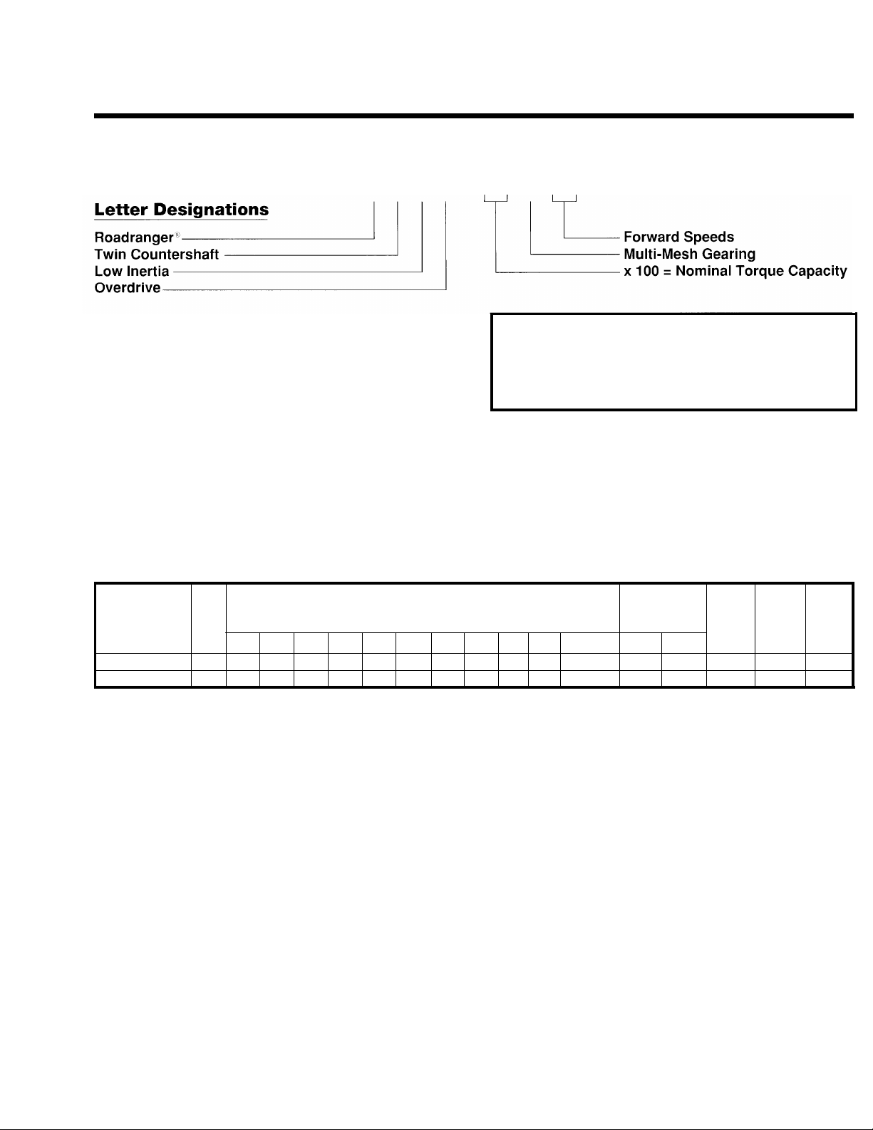
MODEL DESIGNATIONS
AND SPECIFICATIONS
Nomenclature:
RTLO-14613
IMPORTANT: All Fuller Transmissions are identified by
model and serial number. This information is stamped on
the transmission identification tag and affixed to the case.
DO NOT REMOVE OR DESTROY THE TRANSMISSION
IDENTIFICATION TAG.
13-Speed Transmissions (On/Off Highway):
Relative Speed
Model
RTLO-14613
CHART NOTES:
1.
Lengths measured from face of clutch housing to front bottoming surface of companion flange or yoke.
2.
Weight - Listed weights are with clutch housing* and include standard controls, which consist of gear shift lever housing
and gear shift lever. Weight of standard controls is approximately 10 lbs. (4.5 kg.). All weights are approximate.
No
Spds.
13 DIR
OD
LO
1 St
2nd
14.71
10.20 7.34 5.26 3.78 2.70 1.94 1.39 1.00
Gear Ratios:
3rd 4th
5th 6th 7th
2.28 1.64 1.18
8th
3.89/14.71
.85
3.29/12.45
Reverse
PTO Gear
To Input R.P.M.
Right
Bottom (mm)
.696 .696
1
Length
Weight
In.
(Kgs.)
324
(823.5) (339.3)
2
Lbs.
748
3
Oil Cap.
Pints
(Liters)
28
(13.25)
3.
Oil Capacities are approximate, depending on inclination of engine and transmission. Always fill transmission with proper
grade and type of lubricant to level of filler opening. See LUBRICATION.
*For information on available clutch housings refer to Publication FUL-140 – “Clutch Housing Chart”.
3
Page 7
LUBRICATION
, ... . . .
Proper
Lubrication . . .
the Key to long
transmission life
Proper lubrication procedures are the key to a
good all-around maintenance program. If the
oil is not doing its job, or if the oil level is
ignored, all the maintenance procedures in the
world are not going to keep the transmission
running or assure long transmission life.
so that the internal parts operate in a bath of
oil circulated by the motion of gears and shafts.
these procedures are closely followed:
Eaton
First 3,000 to 5,000 miles
(4827 to 8045 Km)
Every 10,000 miles
(16090 Km)
Every 250,000 miles
(402336 Km)
Every 100,000 miles (160,000 Km)
or every 3 years whichever occurs first fluid.
I
First 30 hours Factory fill Initial drain,
Every 40 hours Inspect fluid level Check for leaks
Every 500 hours Change transmission fluid where
I
Every 1,000 hours
I
I
First 3,000 to 5,000 miles Factory fill
(4827 to 8045 Km)
I
Every 10,000 miles
(16090 Km)
I
Every 50,000 miles
(80450 Km)
I
I
First 30 hours Change transmission lubricant on new units
Every 40 hours
Every 500 hours Change transmission Iubricant where
Every 1,000 hours Change transmission Iubricant
Change the oil filter when fluid or lubricant is changed.
®
Eaton
Fuller®Transmissions are designed
Thus, ail parts will be amply lubricated if
1. Maintain oil level. Inspect regularly.
2. Change oil regularly.
3. Use the correct grade and type of oil.
4. Buy from a reputable dealer.
Lubrication Change and Inspection
®
Roadranger®CD50 Transmission Fluid
HIGHWAY USE—Heavy Duty and Mid-Range
Factory fill
Inltlal drain
Check fluid level
Check for leaks
Heavy Duty Highway Change Interval
Change transmission
Mid-Range Highway Change Interval
Change transmission
OFF-HIGHWAY USE
severe dirt conditions exist.
Change transmission fluid
(Normal off-highway use),
Heavy Duty Engine Lubricant or
Mineral Gear Lubricant
HIGHWAY USE
Initial drain.
Inspect Iubricant level,
Check for leaks,
Change transmission
OFF-HIGHWAY USE
Inspect Iubricant level Check for leaks
severe dirt conditions exist.
(Normal off-highway use),
lubricant,
fluid,
Recommended Lubricants
Fahrenheit
(Celsius)
Ambient
Temperature
All
Above 10oF(-12oC.)
Above 10oF(-12oC.)
Below 10oF(-12oC.)
Above 10oF(-12oC.)
Below 10oF(-12oC.)
®
Grade
(SAE)
50
50
40
90
80W
Type
Eaton®Roadranger
CD50 Transmission
Fluid
Heavy Duty Engine 011
MI L-L-2104B C or D or
API-SF or API-CD
(Previous API designations 30
acceptable)
Mineral Gear 011 with rust
and oxidation Inhibitor
API-GL-1
The use of mild EP gear oil or multi-purpose gear oil is not recommended, but if
these gear oils are used, be sure to adhere to
the following limitations:
Do not use mild EP gear oil or multi-pur-
pose gear oil when operating temperatures are
above 230°F (110
o
C). Many of these gear oils,
particularly 85W140, break down above 230°F
and coat seals, bearings and gears with deposits that may cause premature failures. If
these deposits are observed (especially a coating on seal areas causing oil leakage), change
to Eaton Roadranger CD50 transmission fluid,
heavy duty engine oil or mineral gear oil to
assure maximum component life and to maintain your warranty with Eaton. (Also see
“Operating Temperatures”.)
Additives and friction modifiers are not recom-
mended for use in Eaton Fuller transmissions.
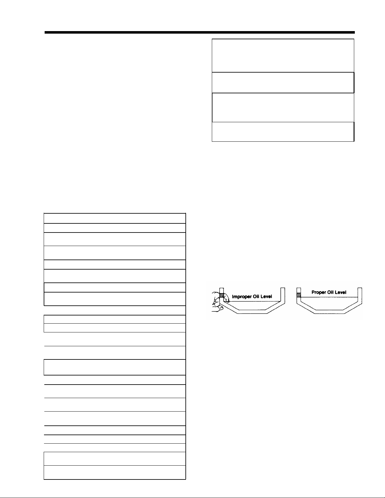
Proper Oil Level
Make sure oil is level with filler opening. Because you can reach oil with your finger does
not mean oil is at proper level. One inch of oil
level is about one gallon of oil.
Draining Oil
Drain transmission while oil is warm. To drain
oil remove the drain plug at bottom of case.
Clean the drain plug before re-installing.
Refilling
Clean case around filler plug and remove plug
from side of case. Fill transmission to the
level of the filler opening. If transmission has
two filler openings, fill to level of both openings.
The exact amount of oil will depend on the
transmission inclination and model. Do not
over fill—this will cause oil to be forced out
of the transmission.
When adding oil, types and brands of oil
should not be mixed because of possible incompatibility.
4
Page 8
LUBRICATION
Operating Temperatures
—With Eaton
®
Roadranger
®
CD50 Transmission Fluid
Heavy Duty Engine Oil
and Mineral Oil
The transmission should not be operated consistently at temperatures above 250
However, intermittent operating temperatures
o
to 300
F (149oC) will not harm the transmission. Operating temperatures above 250
increase the lubricant’s rate of oxidation and
shorten its effective life. When the average
operating temperature is above 250
transmission may require more frequent oil
changes or external cooling.
The following conditions in any combina-
tion can cause operating temperatures of over
o
F: (1) operating consistently at slow
250
speeds, (2) high ambient temperatures, (3) restricted air flow around transmission, (4) exhaust system too close to transmission, (5)
high horsepower, overdrive operation.
External oil coolers are available to reduce
operating temperatures when the above conditions are encountered.
o
F (120oC).
o
F
o
F, the
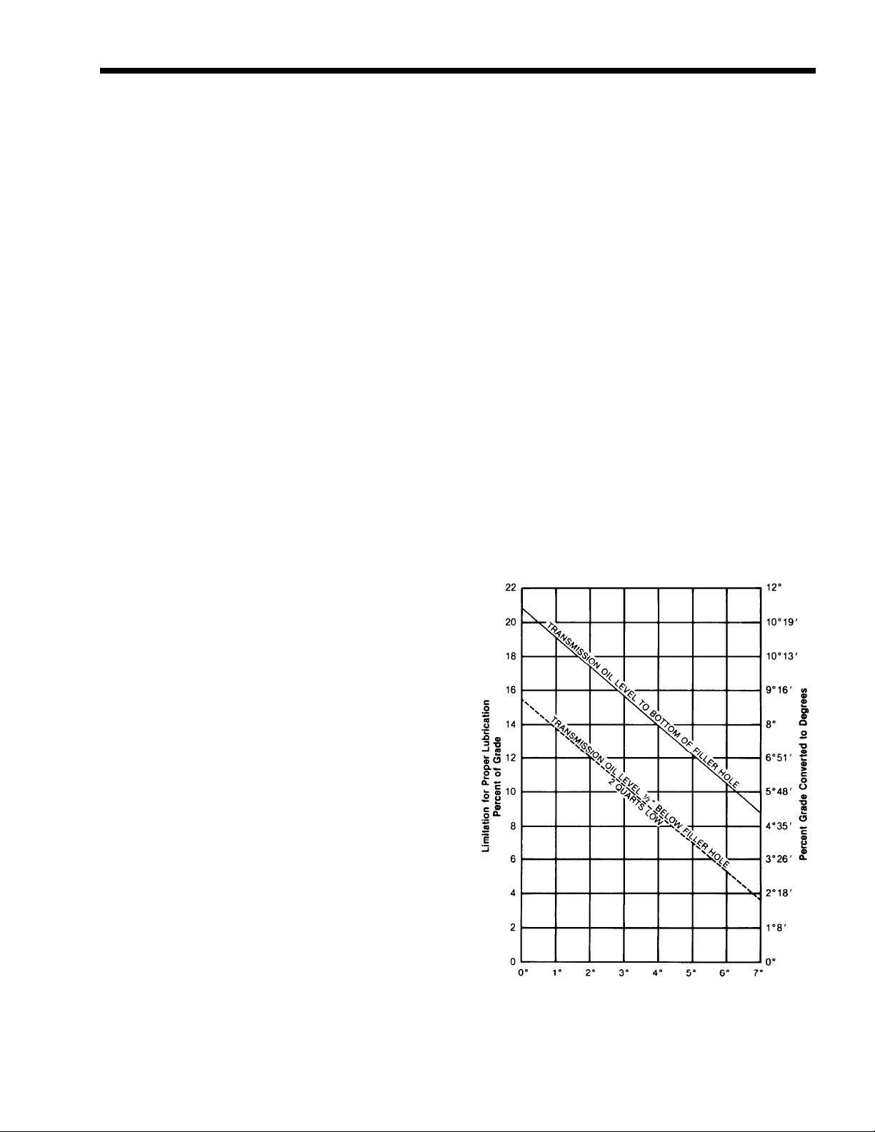
Proper Lubrication Levels
as Related to Transmission
Installation Angles
If the transmission operating angle is more
than 12 degrees, improper lubrication can occur. The operating angle is the transmission
mounting angle in the chassis plus the percent of upgrade (expressed in degrees).
The chart below illustrates the safe percent
of upgrade on which the transmission can be
used with various chassis mounting angles.
For example: if you have a 4 degree transmis-
sion mounting angle, then 8 degrees (or 14
percent of grade) is equal to the limit of 12
degrees. If you have a O degree mounting
angle, the transmission can be operated on a
12 degree (21 percent) grade.
Anytime the transmission operating angle of
12 degrees is exceeded for an extended
period of time the transmission should be
equipped with an oil pump or cooler kit to
insure proper lubrication.
Note on the chart the effect low oil levels
can have on safe operating angles. Allowing
the oil level to fall 1/2” below the filler plug
hole reduces the degree of grade by approximately 3 degrees (5.5 percent).
Proper Lubrication Levels are Essential!
Transmission Oil Coolers are:
Recommended
— With engines of 350 H.P. and above
with overdrive transmissions
Required
— With engines 399 H.P. and above with
overdrive transmissions and GCW’S
over 90,000 lbs.
— With engines 399 H.P. and above and
1400 Lbs.-Ft. or greater torque
— With engines 450 H.P. and above
With EP or Multipurpose Gear Oil
—
Mild EP gear oil and multipurpose gear oil are
not recommended when lubricant operating
temperatures are above 230°F (110). In addition, transmission oil coolers are not recom-
mended with these gear oils since the oil
cooler materials may be attacked by these
gear oils. The lower temperature limit and oil
cooler restriction with these gear oils generally limit their success to milder applications.
Transmission Mounting Angle
Dotted line showing “2 Quarts Low” is for
reference only. Not recommended.
5
Page 9
OPERATION
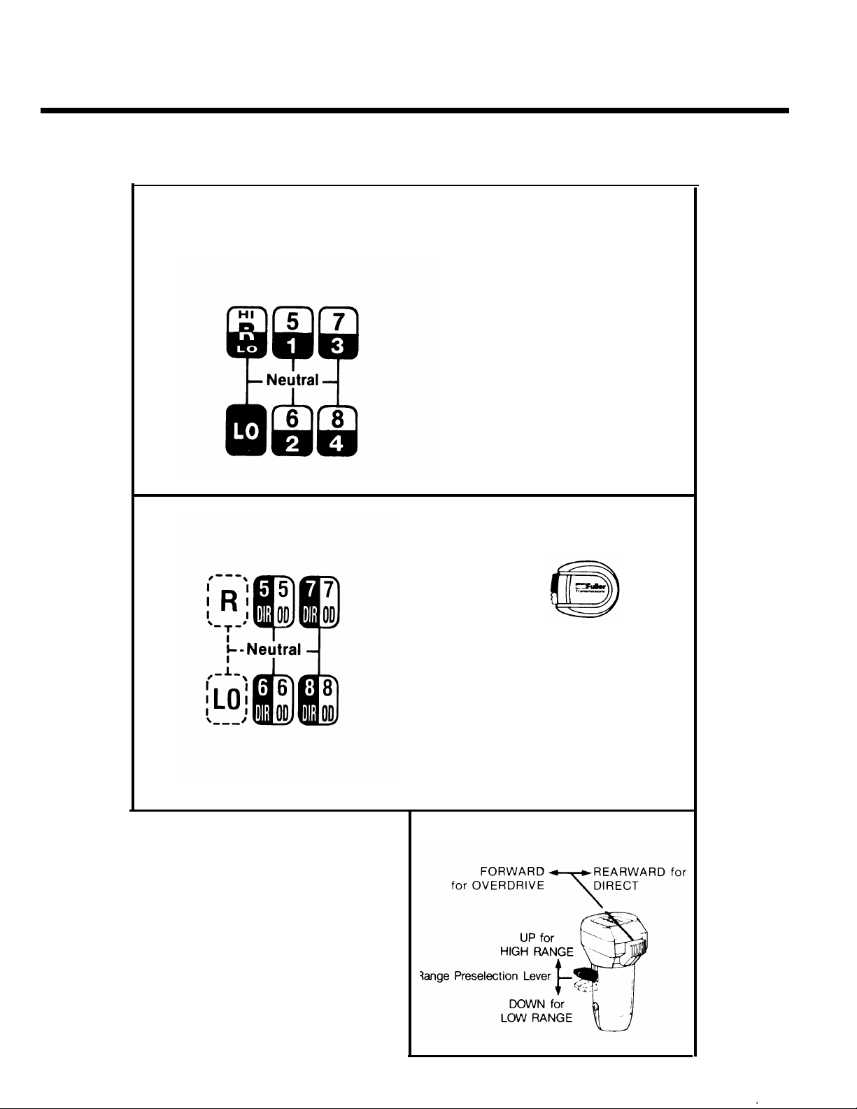
13-Speed Overdrive Models
Shift Lever Patterns and Shifting Controls
RTO (Overdrive) Models
RTOX (Double-Overdrive) Models
With Splitter Control But”
ton in “DIR.’’/REARWARD
position . . .
Shift LO-1-2-3-4 in LOW
RANGE.
Range shift . . .
And shift 5.6-7-8 in HIGH
RANGE (Direct).
WHILE IN HIGH RANGE
ONLY . . .
Ratios can be split by
moving Splitter Control
Button to the "O.D.”/
FORWARD position to
gain OVERDRIVE 5-6-7-8.
Roadranger Valve
(A-4900)
SPLITTER CONTROL BUTTON
6
. .—.
Page 10
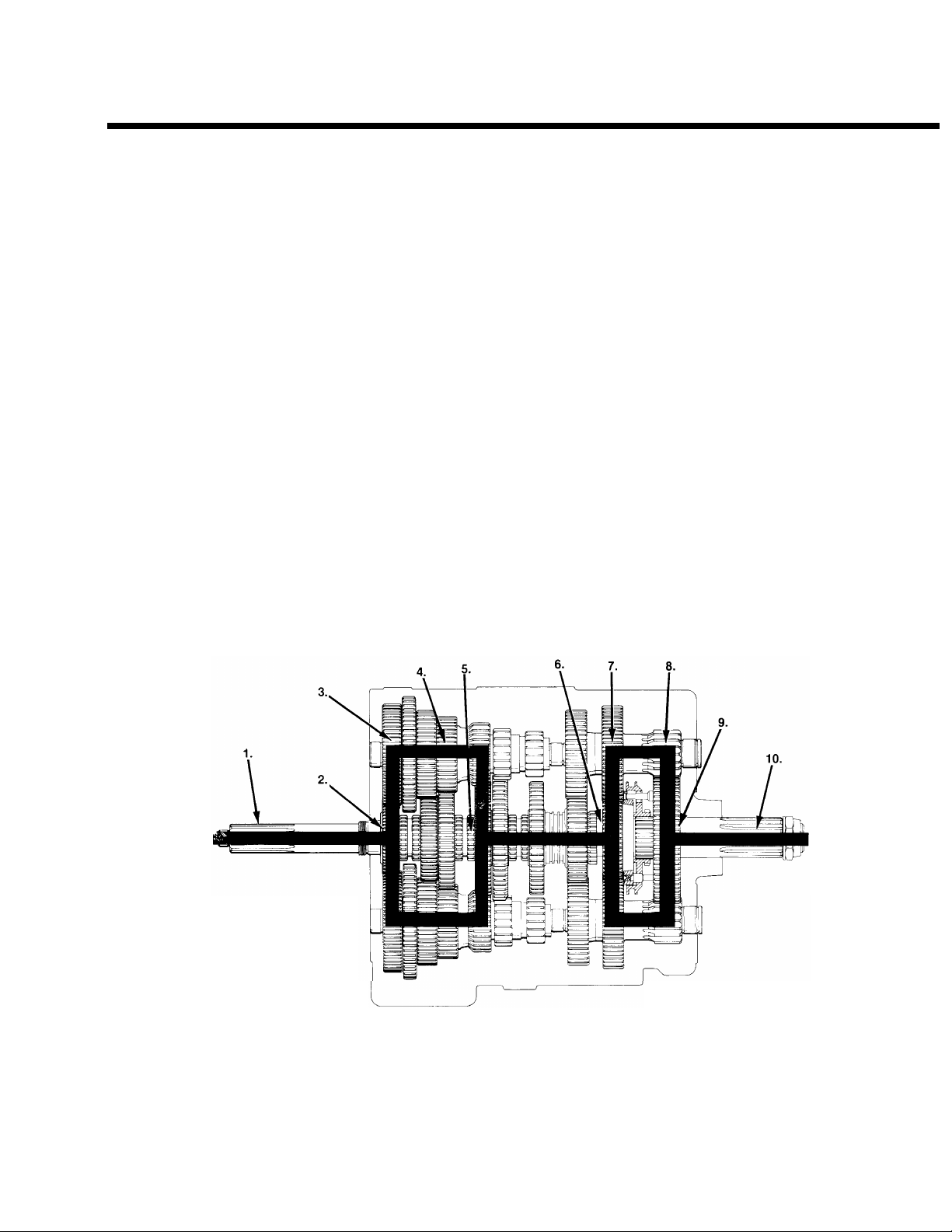
POWER FLOW
The transmission must efficiently transfer the engine’s power, in terms of torque, to the vehicle’s rear wheels.
Knowledge of what takes place in the transmission during torque transfer is essential when troubleshooting
and making repairs.
Front Section Power Flow
(LO Range Direct)
1.
Power (torque) from the vehicle’s engine is transferred to the transmission’s input shaft.
2.
Splines of input shaft engage internal splines in
hub of main drive gear.
Torque is split between the two countershaft
3.
drive gears.
Torque is delivered along both countershaft to
4.
mating countershaft gears of “engaged” main- 10.
shaft gear. The following cross section views illustrate a 1st/5th speed gear engagement.
Internal clutching teeth in hub of engaged main-
5.
shaft gear transfers torque to mainshaft through
sliding clutch.
Mainshaft transfers torque directly to rear aux-
6.
iliary drive gear.
LO RANGE DIRECT
7.
The rear auxiliary drive gear splits torque between the two auxiliary countershaft drive gears.
8.
Torque is delivered along both auxiliary countershaft to the “engaged” reduction gear on output
shaft.
Torque is transferred to output shaft through slid-
9.
ing clutch.
Output shaft delivers torque to driveline.
Cut 8006C-11 /87
7
Page 11
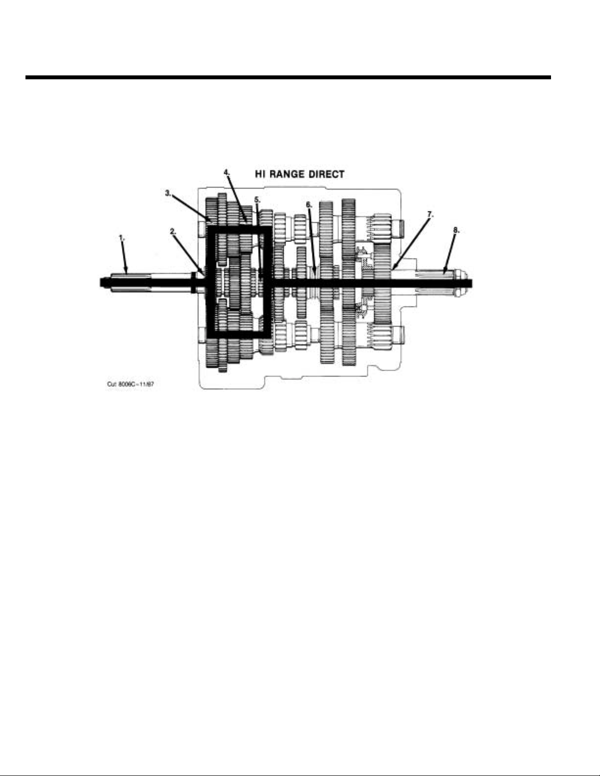
POWER FLOW
Auxiliary Section Power Flow:
HI7.RANGE DIRECT
The rear auxiliary drive gear transfers torque
directly to the output shaft through –engaged”
sliding clutch.
8. Torque is delivered through theoutput shaft to
driveline as HI RANGE 5th gear.
8
Page 12
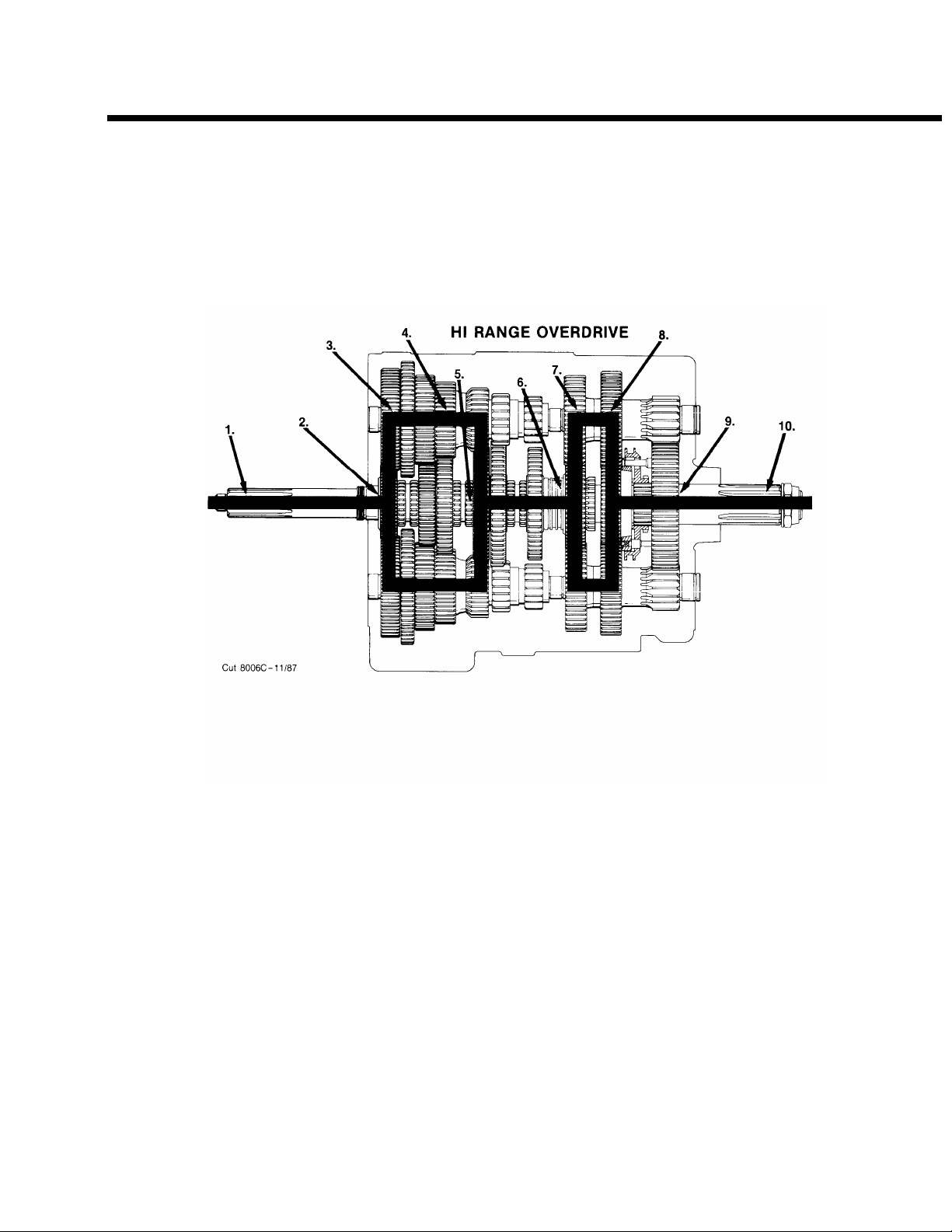
POWER FLOW
Auxiliary Section Power Flow:
HI
RANGE OVERDRIVE
7.
The front auxiliary drive gear splits torque between the two auxiliary countershaft drive gears. sliding clutch.
Torque is delivered along both auxiliary counter- 10. Output shaft delivers torque to driveline as HI
8.
shafts to mating countershaft gears of
“engaged” rear auxiliary drive gear.
9. Torque is transferred to output shaft through the
Range 5th gear OVERDRIVE.
9
Page 13
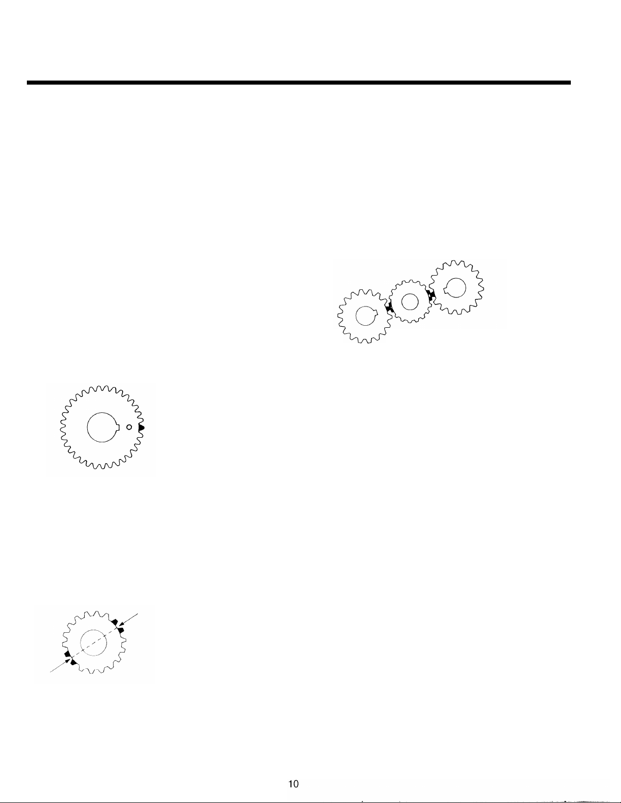
TIMING
Timing Procedures: All ModeIs
It is essential that both countershaft assemblies of
the front and auxiliary sections are “timed. ” This assures proper tooth contact is made between mainshaft gears seeking to center on the mainshaft
during torque transfer and mating countershaft gears
that distribute the load evenly. If not properly timed,
serious damage to the transmission is likely to result
from unequal tooth contact causing the mainshaft
gears to climb out of equilibrium.
Timing is a simple procedure of marking the appropriate teeth of a gear set prior to installation and
placing them in proper mesh while in the transmis-
sion. In the front section, it is necessary to time only
the drive gear set. And depending on the model, only
the LO range, deep reduction, or splitter gear set is
timed in the auxiliary section.
Front Section
A. Marking countershaft drive gear teeth.
1.
Prior to placing each countershaft assembly
into case, clearly mark the tooth located
directly over the keyway of drive gear as
shown. This tooth is stamped with an “O” to
aid identification.
C. Meshing marked countershaft drive gear teeth
with marked main drive gear teeth.
(After placing the mainshaft assembly into case,
the countershaft bearings are installed to complete installation of the countershaft assemblies.)
1.
When installing the bearings on left countershaft, mesh the marked tooth of countershaft
drive gear with either set or two marked teeth
on the main drive gear.
2.
Repeat the procedure when installing the
bearings on right countershaft, making use of
the remaining set of two marked teeth on the
main drive gear to time assembly.
Countershaft gear teeth
meshed with drive gear teeth
for correct timing.
Cut
7300 F-1 1/86
Tooth on Countershaft
directly over Keyway
marked for timing
Cut 7300 H-11/86
B. Marking main drive gear teeth.
1.
Mark any two adjacent teeth on the main drive
gear.
2.
Mark the two adjacent teeth located directly
opposite the first-set marked on the main drive
gear. As shown below, there should be an
equal number of unmarked gear teeth on each
side between the marked sets.
Drive gear teeth correct/y
marked for timing.
Cut 7300 G-11/86
Auxiliary Section
A. Timing the auxiliary countershaft and LO range
gear.
1.
Mark any two adjacent teeth on “the LO range
gear of set to be timed. Then mark the two adjacent teeth located directly opposite the first
set marked as shown in Illustration B.
2.
Prior to placing each auxiliary countershaft assembly into housing, mark the tooth stamped
with an “O” on gear to mate with timed mainshaft gear as shown in Illustration A.
Install the LO range gear on the out put shaft
3.
and into the auxiliary case.
4.
Seat the auxiliary countershaft bearings.
5.
Install the rear bearing cover and tighten to
recommended torque.
Place the auxiliary countershaft assemblies
6.
into position and mesh the marked teeth of the
mating countershaft gears with the marked
teeth of the LO range gear as shown in illustration C.
Page 14
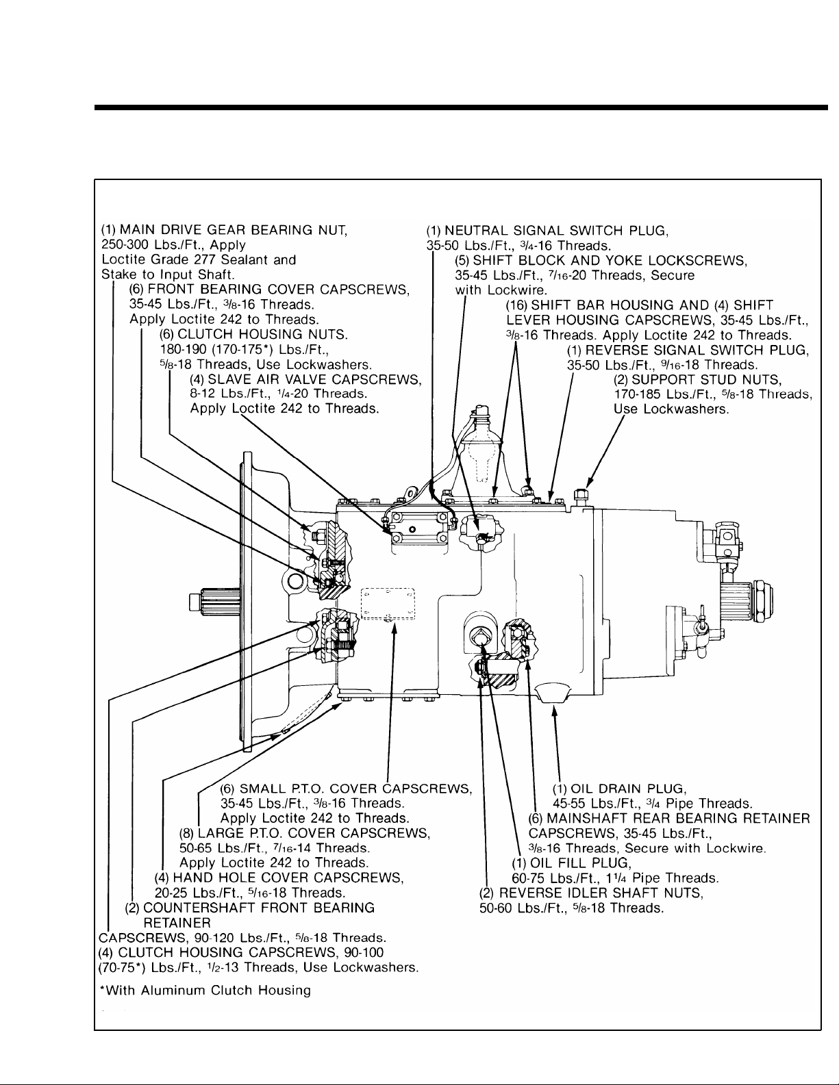
TORQUE RECOMMENDATIONS
Correct torque application is extremely important to assure long transmission life and dependable performance.
Over-tightening or under-tightening can result in a loose installation and, in many instances, eventually cause
damage to transmission gears, shafts, and/or bearings. Use a torque wrench whenever possible to attain recommended lbs./ft. ratings. Do not torque capscrews dry.
FRONT SECTION: ALL MODELS
1
Cut 7190 K-11/87
11
Page 15
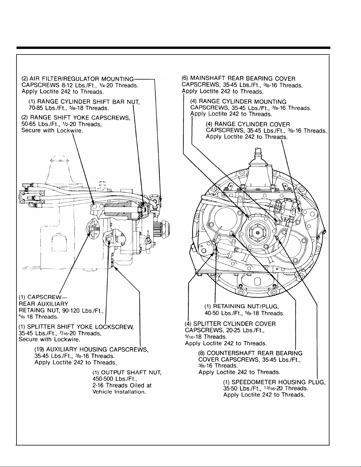
TORQUE RECOMMENDATIONS
AUXILIARY SECTIONS
Cut 7191 Q-11/87
12
Page 16

TOOL REFERENCE
Some repair procedures pictured in this manual show
the use of specialized tools. Their actual use is recom-
mended as they make transmission repair easier, faster,
and prevent costly damage to critical parts.
But for the most part, ordinary mechanic’s tools such as
socket wrenches, screwdrivers, etc., and other standard
shop items such as a press, mauls and soft bars are all that
is needed to successfully disassemble and reassemble any
Fuller Transmission.
PAGE
38
46
47
47
Tension Spring Driver
Countershaft Retaining Strap
Auxiliary Section Hanger Bracket
Output Shaft Hanger Bracket
TOOL
The specialized tools listed below can be obtained from
a tool supplier or made from dimensions as required by the
individual user. Detailed Fuller Transmission Tool Prints are
available upon request by writing.
Eaton Corporation
Transmission Dept.
Technical Service Dept.
P.O. Box 4013
Kalamazoo, Michigan 49003
HOW OBTAINED
Made from Fuller Transmission
Print T-11938
Made from Fuller Transmission
Print T-64553
Made from Fuller Transmission
Print T-22823
Made from Stop Nut or Round
Bar Stock Flat Steel Stock
5 2 Jaw Puller and Bearing Separator
69
72
97
Impact Puller (1/2-13 Threaded End)
Snap Ring Pliers
Countershaft Support Tool
99 Input Shaft Bearing Driver
113
Torque Wrench, 1000 Lbs./Ft. Capacity
Tool Supplier
Tool Supplier
Tool Supplier
Made from Fuller Transmission
Print T-22247
Tool Supplier
Tool Supplier
13
Page 17
PREVENTIVE MAINTENANCE
14
Page 18

PREVENTIVE MAINTENANCE
PREVENTIVE MAINTENANCE CHECK CHART
CHECKS WITHOUT PARTIAL
DISASSEMBLY OF CHASSIS OR CAB
1.
Air System and Connections
a. Check for leaks, worn air lines, loose con-
nections and capscrews. See AIR SYSTEM.
2.
Clutch Housing Mounting
a. Check all capscrews of clutch housing for
looseness.
Clutch Release Bearing (Not Shown)
3.
Remove hand hole cover and check radial
a.
and axial clearance in release bearing.
b. Check relative position of thrust surface of
release bearing with thrust sleeve on pushtype clutches.
4.
Clutch Pedal Shaft and Bores
Pry upward on shafts to check wear.
a.
b. If excessive movement is found, remove
clutch release mechanism and check bush-
ings in bores and wear on shafts.
Lubricant
5.
a. Change at specified service intervals.
b. Use only the types and grades as recom-
mended. See LUBRICATION.
Filler and Drain Plugs
6.
Remove filler plugs and check level of lubri-
a.
cant at specified intervals. Tighten filler and
drain plugs securely.
7.
Capscrews and Gaskets
a. Check all capscrews, especially those on
PTO covers and rear bearing covers for
looseness which would cause oil leakage.
See TORQUE RECOMMENDATIONS.
b. Check PTO opening and rear bearing covers
for oil leakage due to faulty gasket.
8.
Gear Shift Lever
a.
Check for looseness and free play in housing. If lever is loose in housing, proceed
with Check No. 9.
9. Gear Shift Lever Housing Assembly
Remove air lines at slave valve and remove
a.
the gear shift lever housing assembly from
transmission.
b. Check tension spring and washer for set
and wear.
Check the gear shift lever spade pin and
c.
slot for wear.
d. Check bottom end of gear shift lever for
wear and check slot of yokes and blocks in
shift bar housing for wear at contact points
with shift lever.
CHECKS WITH DRIVE LINE DROPPED
10. Universal Joint Companion Flange
or Yoke Nut
a.
Check for tightness. Tighten to recommended torque.
11. Output Shaft (Not Shown)
a.
Pry upward against output shaft to check
radial clearance in mainshaft rear bearing.
CHECKS WITH UNIVERSAL JOINT
COMPANION FLANGE OR YOKE
REMOVED
NOTE: If necessary, use solvent and shop rag to
clean sealing surface of companion flange or
yoke. DO NOT USE CROCUS CLOTH, EMERY
PAPER OR OTHER ABRASIVE MATERIALS
THAT WILL MAR SURFACE FINISH.
12. Splines on Output Shaft
(Not Shown)
Check for wear from movement and chuck-
a.
ing action of the universal joint companion
flange or yoke.
13. Mainshaft Rear Bearing Cover
Check oil seal for wear.
a.
15
Page 19

PRECAUTIONS
Disassembly
It is assumed in the detailed disassembly instructions that the lubricant has been drained from transmission,
the necessary linkage and air lines disconnected and the transmission has been removed from vehicle chassis.
Removal of the gear shift lever housing assembly (or remote control assembly) is included in the detailed instructions (Disassembly and Reassembly—Shifting Controls); however, this assembly MUST be detached from
shift bar housing before transmission can be removed.
FOLLOW CLOSELY EACH PROCEDURE IN THE DETAILED INSTRUCTIONS. MAKING USE OF THE TEXT. ILLUS-
TRATIONS AND PHOTOGRAPHS PROVIDED.
1
BEARINGS — Carefully wash and relubricate all
reusable bearings as removed and protectively
wrap until ready for use. Remove bearings planned
to be reused with pullers designed for this pur-
pose.
2. ASSEMBLIES — When disassembling the various
assemblies, such as the mainshaft, countershaft,
and shift bar housing, lay all parts on a clean
bench in the same sequence as removed. This procedure will simplify reassembly and reduce the
possibility of losing parts.
3. SNAP RINGS — Remove snap rings with Pliers designed for this purpose. Snap rings removed in this
manner can be reused, if they are not sprung or
loose.
4
INPUT SHAFT — The input shaft can be removed
from transmission without removing the coun-
tershafts, mainshaft, or main drive gear. Special
procedures are required and provided in this manual.
5.
CLEANLINESS — Provide a clean place to work. It
is important that no dirt or foreign material enters
the unit during repairs, Dirt is an abrasive and can
damage bearings. It is always good practice to
clean the outside of the unit before starting the
planned disassembly.
6. WHEN USING TOOLS TO MOVE PARTS — Always
apply force to shafts, housings, etc, with restraint.
Movement of some parts is restricted. Never apply
force to the part being driven after it stops solidly.
The use of soft hammers, bars and mauls for all
disassembly work is recommended.
Inspection
Before reassembling the transmission, check each part carefully for abnormal or excessive wear and damage to
determine reuse or replacement. When replacement is necessary, use only genuine Fuller Transmission parts to
assure continued performance and extended life from your unit.
Since the cost of a new part is generally a small fraction of the total cost of downtime and labor, avoid reusing a questionable part which could lead to additional repairs and expense soon after initial reassembly. To aid
in determining the reuse or replacement of any transmission part, consideration should also be given to the
unit’s history, mileage, application, etc.
Recommended inspection procedures are provided in the following checklist.
A. BEARINGS
1.
Wash all bearings in clean solvent. Check
balls, rollers and raceways for pitting, discoloration, and spalled areas. Replace bearings
that are pitted, discolored, or spalled.
2.
Lubricate bearings that are not pitted, discolored, or spalled and check for axial and radial
clearances.
3.
Replace bearings with excessive clearances.
4.
Check bearing fits. Bearing inner races
should be tight to shaft; outer races slightly
tight to slightly loose in case bore. If bearing
spins freely in bore, however, case should be
replaced.
B. GEARS
1. Check gear teeth for frosting and pitting.
Frosting of gear tooth faces present no threat
of transmission failure. Often in continued
operation of the unit, frosted gears will “heal”
and not progress to the pitting stage. And in
most cases, gears with light to moderate pitted teeth have considerable gear life remain-
ing and can be reused. But gears with
advanced stage pitting should be replaced.
2. Check for gears with clutching teeth abnormally worn, tapered, or reduced in length
from clashing in shifting. Replace gears
found in any of these conditions.
16
Page 20

PRECAUTIONS
Inspection (cont’d.)
3.
Check axial clearance of gears. Where exces-
sive clearance is found, check gear snap ring,
washer, spacer, and gear hub for excessive
wear. Maintain .005” to .012” axial clearance
between mainshaft gears.
C. SPLINES
1. Check splines on all shafts for abnormal wear.
If sliding clutch gears, companion flange, or
clutch hub have worn into the sides of the
splines, replace the specific shaft affected.
D. TOLERANCE WASHERS
1. Check surfaces of all tolerance washers.
Washers scored or reduced in thickness
should be replaced.
E. REVERSE IDLER GEAR ASSEMBLIES
1. Check for excessive wear from action of roller
bearings.
F. GRAY IRON PARTS
1. Check all gray iron parts for cracks and breaks.
Replace parts found to be damaged.
G. CLUTCH RELEASE PARTS
1. Check clutch release parts. Replace yokes
worn at cam surfaces and bearing carrier
worn at contact pads.
2. Check pedal shafts. Replace those worn at
bushing surfaces.
1. GEAR SHIFT LEVER HOUSING
ASSEMBLY
1. Check spring tension on shift lever. Replace
tension spring and washer if lever moves too
f reel y.
2. If housing is disassembled, check spade pin
and corresponding slot in lever for wear. Re-
place both parts if excessively worn.
J. BEARING COVERS
1. Check covers for wear from thrust of adjacent
bearing. Replace covers damaged from thrust
of bearing outer race.
2. Check bores of covers for wear. Replace
those worn oversize.
K. OIL RETURN THREADS
AND SEALS
1. Check oil return threads in front bearing
cover. If sealing action of threads has been
destroyed by contact with input shaft, replace
bearing cover.
2. Check oil seal in rear bearing cover If sealing
action of lip has been destroyed, replace seal.
L. SLIDING CLUTCHES
1. Check all shift yokes and yoke slots in sliding
clutches for extreme wear or discoloration
from heat.
2. Check engaging teeth of sliding clutches for
partial engagement pattern.
H. SHIFT BAR HOUSING ASSEMBLY
1.
Check for wear on shift yokes and blocks at
pads and lever slot. Replace excessively worn
parts.
2.
Check yokes for correct alignment. Replace
sprung yokes.
3.
Check Iockscrews in yokes and blocks.
Tighten and rewire those found loose.
4.
If housing has been disassembled, check
neutral notches of shift bars for wear from interlock balls.
M. SYNCHRONIZER ASSEMBLY
1. Check synchronizer for burrs, uneven and ex-
cessive wear at contact surface, and metal
particles.
2. Check blocker pins for excessive wear or
looseness.
3. Check synchronizer contact surfaces on the
auxiliary drive and low range gears for excessive wear.
N. O-RINGS
1. Check all O-rings for cracks or distortion. Re-
place if worn.
17
Page 21

PRECAUTIONS
Reassembly
Make sure that interiors of case and housings are clean. It is important that dirt and other foreign materials be
kept out of the transmission during reassembly. Dirt is an abrasive and can damage polished surfaces of
bearings and washers. Use certain precautions, as listed below, during reassembly.
1.
GASKETS — Use new gaskets throughout the
transmission as it is being rebuilt. Make sure all
gaskets are installed. An omission of any gasket
can result in oil leakage or misalignment of
bearing covers.
CAPSCREWS — To prevent oil leakage, use Loctite
2.
242 thread sealant on all capscrews. For torque
ratings, see TORQUE RECOMMENDATIONS.
O-RINGS — Lubricate all O-rings with silicone lu-
3.
bricant.
4.
ASSEMBLY — Refer to the illustrations provided in
the detailed disassembly instructions as a guide
to reassembly.
INITIAL LUBRICATION — Coat all limit washers
5.
and splines of shafts with Lubriplate during reassembly to prevent scoring and galling of such
parts.
6.
AXIAL CLEARANCES — Maintain original axial
clearances of .005” to .012” for mainshaft gears.
7.
BEARINGS — Use of flanged-end bearing drivers is
recommended for the installation of bearings.
These special drivers apply equal force to both
bearing races, preventing damage to balls/rollers
and races while maintaining correct bearing alignment with bore and shaft. Avoid using a tubular or
sleeve-type driver, whenever possible, as force is
applied to only one of the bearing races. See
TOOL REFERENCE.
8.
UNIVERSAL JOINT COMPANION FLANGE OR
YOKE — Pull the companion flange or yoke tightly
into place with the output shaft nut, using 450-500
foot-pounds of torque. Make sure the speedome-
ter drive gear or a replacement spacer of the same
width has been installed. Failure to pull the com-
panion flange or yoke tightly into place will permit
the output shaft to move axially with resultant
damage to the rear bearing.
—
IMPORTANT: REFER TO THE APPROPRIATE ILLUSTRATED PARTS LIST (SPECl-
FIE D BY MODEL SERIES) TO ENSURE THAT PROPER PARTS ARE
USED DURING REASSEMBLY OF THE TRANSMISSION.
18
Page 22
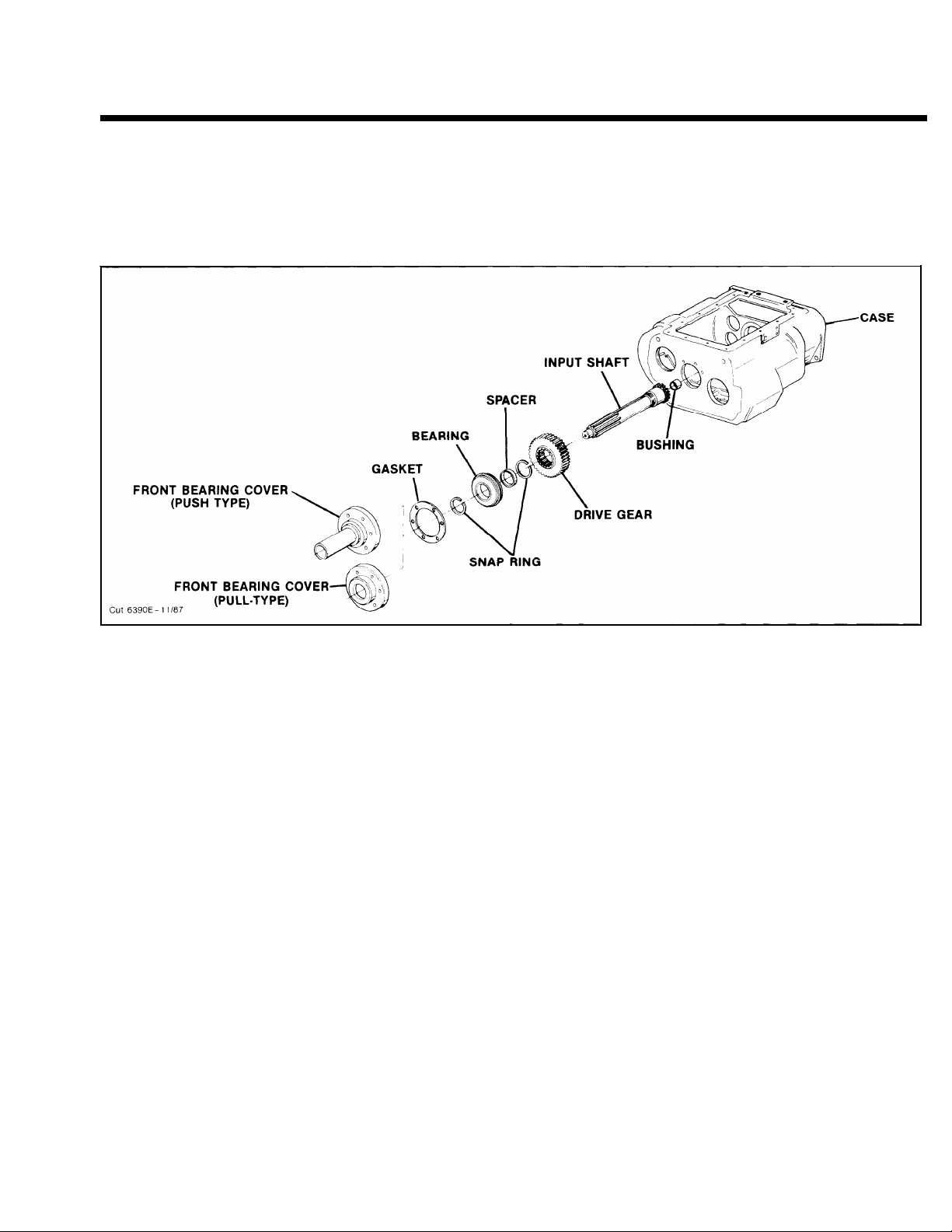
CHANGING
INPUT SHAFT
Special Procedure
In some cases, it may become necessary to replace the input shaft due to excessive clutch wear on the splines.
Except for removal of the shift bar housing assembly, the input shaft can be removed without further disas-
sembly of the transmission. Removal of the clutch housing is optional.
NOTE: The following illustration and instructions pertain to changing the input shaft ONLY. To change the main
drive gear, complete disassembly of the front section is required.
Disassembly
1.
Remove the gear shift lever housing assembly (or
remote control assembly) from shift bar housing,
and the shift bar housing assembly from transmission case.
2.
Remove the front bearing cover and gasket. If necessary, remove the O-ring from cover of models so
equipped.
Remove the bearing retaining snap ring from
3.
groove in shaft.
4.
Push down on input shaft to cock bearing in bore.
Drive input shaft toward rear of transmission,
through bearing as far as possible. Pull input shaft
forward to expose snap ring of bearing.
5.
Use pry bars to complete removal of bearing.
6.
Remove drive gear spacer and snap ring.
7.
Pull input shaft forward and out of drive gear and
case.
Reassembly
1.
If necessary, install bushing in pocket of input
shaft.
Install new input shaft into splines of main drive
2.
gear, just far enough to expose snap ring groove
in I.D. of drive gear.
Install snap ring in snap ring groove inside drive
3.
gear.
Install drive gear spacer on input shaft.
4.
Install drive gear bearing on input shaft and into
5.
case bore.
Install bearing retainer snap ring.
6.
Install front bearing cover and gasket. Make sure
7.
to align oil return hole in the case with hole in
cover.
To facilitate proper reinstallation of the shift bar
8.
housing assembly on case, make sure mainshaft
sliding clutches are placed in the neutral position.
Reinstall the shift bar housing assembly, the
9.
front bearing cover and all other parts and assemblies previously removed, making sure to replace the gaskets used.
19
Page 23
AIR SYSTEM
21
Page 24

AIR SYSTEM
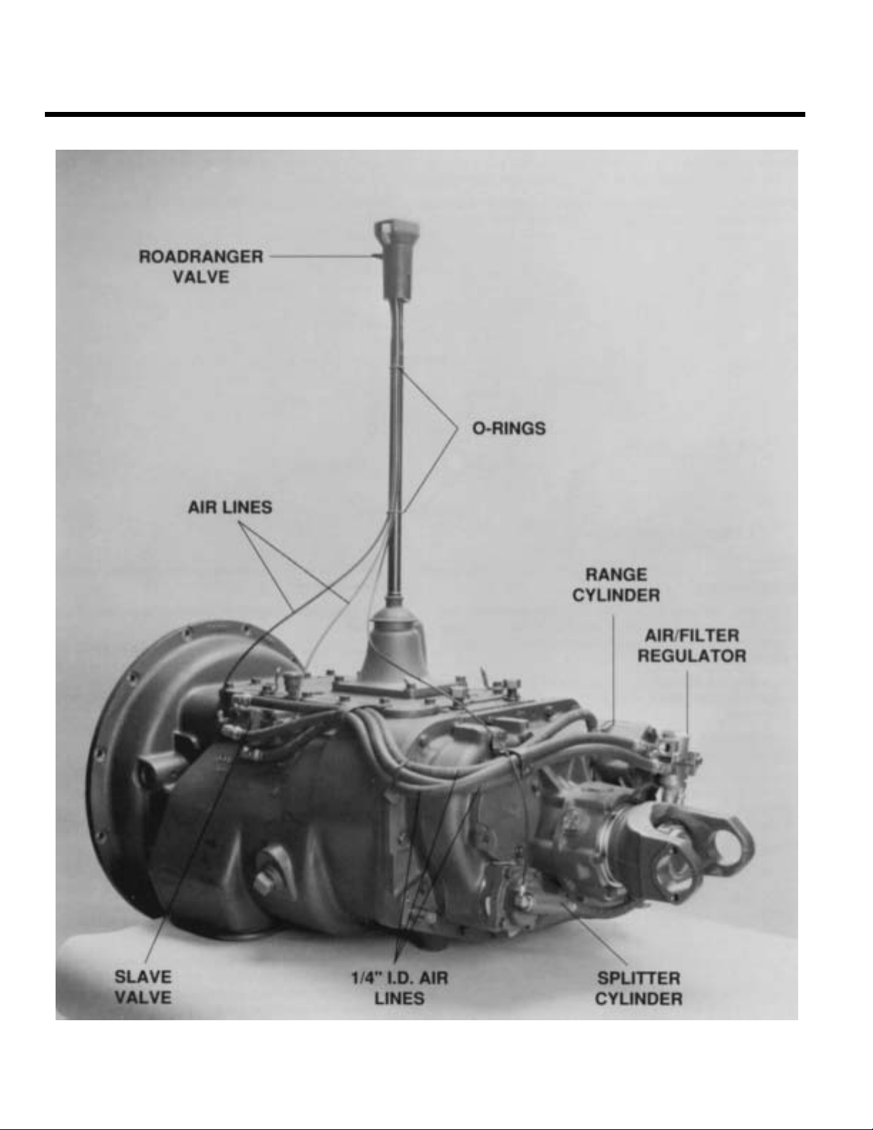
RANGE SHIFT AIR SYSTEM
Operation
The Range Shift Air System consists of the air filter/
regulator, slave valve, a Range Control Valve or Master Control Valve, range cylinder, fittings and
connecting air lines. See Air System Schematics.
CONSTANT AIR from the air filter/regulator is sup-
plied to the “S” or Supply Port of slave valve and
passed through to the INLET or “S” Port of control
valve.
WHILE IN LO RANGE, the control valve is OPEN
and AIR is returned to slave valve at the “P” or End
Port. This signals the valve to supply AIR in line between the LO Range or “L” Port of slave valve and
the LO Range Port of range cylinder housing. AIR received at this port moves the range piston to the rear
and causes the auxiliary LO RANGE gear to become
engaged.
WHILE IN HI RANGE, the control valve is CLOSED
and NO AIR is returned to the slave valve. This
signals the slave valve to supply AIR in line between
the HI Range or “H” Port of valve and the HI Range
Port of range cylinder cover. AIR received at this port
moves the range piston forward to engage the auxiliary drive gear with sliding clutch and bypass the
LO RANGE gear set.
Range shifts can be made ONLY when the gear
shift lever is in, or passing through, neutral. Thus, the
range desired can be PRESELECTED while the shift
lever is in a gear position. As the lever is moved
through neutral, the actuating plunger in the shift bar
housing releases the slave valve, allowing it to move
to the selected range position.
Trouble Shooting
If the transmission fails to make a range shift or
shifts too slowly, the fault may be in the Range Shift
Air System or actuating components of the shift bar
housing assembly.
To locate the trouble, the following checks should
be made with normal vehicle air pressure applied to
the system, but with the engine off.
NEVER WORK UNDER A VEHICLE
WHILE ENGINE IS RUNNING as
personal injury may result from the sudden and unintended movement of vehicle under power. Always
place transmission in the neutral position.
1. INCORRECT AIR LINE HOOK-UPS
(See Air System Schematics)
With the gear shift lever in neutral, move the control that provides range selection UP and DOWN.
A. If the air lines are crossed between control
valve and slave valve, there will be CONSTANT AIR flowing from the exhaust port of
control valve WHILE IN HI RANGE.
B. If the air lines are crossed between the slave
valve and range cylinder, the transmission
gearing will not correspond with the range selection. A LO RANGE selection will result in a
HI RANGE engagement and vice versa.
2.
AIR LEAKS
With the gear shift lever in neutral, coat all air
lines and fittings with soapy water and check for
leaks, moving the control that provides range selection UP and DOWN.
A.
If there is a steady leak from the exhaust port
of control valve, O-rings and/or related parts
of the control valve are defective.
B.
If there is a steady leak from breather of slave
valve: an O-ring in valve is defective, or there
is a leak past O-rings of range cylinder piston.
If transmission fails to shift into LO RANGE
C.
or is slow to make the range shift and the
case is pressurized, see Check No. 7 of this
section.
Tighten all loose connections and replace de-
D.
fective O-rings and parts.
3.
AIR FILTER/REGULATOR
(See illustration, Page 23.)
With the gear shift lever in neutral, check the
breather of air fiiter/regulator assembly. There
should be NO AIR leaking from this port. The
complete assembly should be replaced if a
steady leak is found.
Cut off the vehicle air supply to the air filter/
regulator assembly, disconnect the air line at fitting in Supply OUTLET and install an air gage in
opened port. Bring the vehicle air pressure to normal. Regulated air pressure should be 57.5 to 62.5
Psi.
DO NOT ADJUST SCREW AT BOTTOM OF REGULATOR TO OBTAIN CORRECT READINGS. The
air regulator has been PREADJUSTED within the
correct operating limits. Any deviation from these
limits, especially with regulators that have been
in operation for some time, is likely to be caused
by dirt or worn parts. If replacement or cleaning
of the filter element does nothing to correct the
air pressure readings, replace the complete assembly, as the air regulator is nonserviceable.
4.
RANGE VALVE (See Page 24.)
With the gear shift lever in neutral, select HI
RANGE and disconnect the air line at the OUTLET or “P” Port of control valve.
21
Page 25
AIR SYSTEM
A.
When LO RANGE is selected, a steady blast
of air will flow from opened port. Select HI
RANGE to shut off air flow. This indicates the
control valve is operating properly. Reconnect
air line.
B.
If control valve does not operate properly,
check for restrictions and air leaks. Leaks indicate defective or worn O-rings.
5.
HI
RANGE OPERATION
With the gear shift lever in neutral, select LO
RANGE and disconnect the 1/4” I.D. air line at the
port of range cylinder cover. Make sure this line
leads from the HI Range or “H” Port of slave
valve.
A.
When HI RANGE is selected, a steady blast of
air should flow from disconnected line. Select
LO RANGE to shut off air flow.
B.
Move the shift lever to a gear position and select HI RANGE. There should be NO AIR flowing from disconnected line. Return the gear
shift lever to the neutral position. There
should now be a steady flow of air from disconnected line. Select LO RANGE to shut off
air flow and reconnect air line.
If the air system does not operate accord-
C.
ingly, the slave valve or actuating components
of the shift bar housing assembly are defective.
IMPORTANT: RANGE PRESELECTION
The plunger pin, located in case bore between
the slave valve and actuating plunger of shift bar
housing, prevents the slave valve from operating
while the shift lever is in a gear position. When
the lever is moved to or through the neutral position, the pin is released and the slave valve becomes operational.
6. LO RANGE OPERATION
With the gear shift lever in neutral, select HI
RANGE and disconnect the 1/4” I.D. air line at the
fitting on range cylinder housing. Make sure this
line leads from the LO Range or “L” Port of slave
valve.
A.
When LO RANGE is selected, a steady blast
of air should flow from disconnected line. Se-
lect HI RANGE to shut off air flow.
B.
Move the shift lever to a gear position and select LO RANGE. There should be NO AIR flowing from disconnected line. Return the gear
shift lever to the neutral position. There
should now be a steady flow of air from disconnected line. Select HI RANGE to shut off
air flow and reconnect air line.
If the air system does not operate accord-
C.
ingly, the slave valve or actuating components
of the shift bar housing assembly are defective.
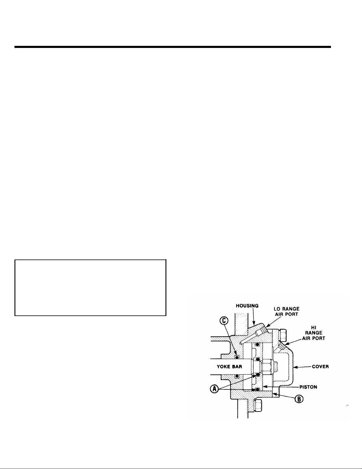
7. RANGE CYLINDER (Refer to the following
illustration.)
If any of the seals in the range cylinder assembly
are defective, the range shift will be affected.
A.
Leak at either O-ring A results in complete
failure to make a range shift; steady flow of
air from breather of slave valve in both
ranges.
B.
Leak at gasket B results in a steady flow of air
to atmosphere while in HI RANGE.
C.
Leak at O-ring C results
RANGE; pressurizing of transmission case.
in a slow shift to LO
22
Cut
7420-5/87
Range Cylinder Assembly—All Models
Page 26
AIR SYSTEM
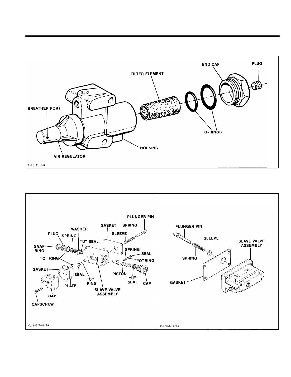
AIR FILTER/REGULATOR ASSEMBLY
The air filter contains a replaceable filter element which can be removed by turning out the end cap. This ele-
ment should be cleaned at each oil change, or more often under high humidity conditions. Replace if necessary.
—.
SLAVE VALVES
POPPET-TYPE
Refer to the drawing for disassembly and reassembly of the piston-type slave valve assemblies. Should the poppet-type slave valve assembly prove to be defective, replace the complete assembly, as it is non-serviceable.
The actuating components used with these valve assemblies are non-interchangeable. Failure to use the correct
plunger pin, spring, and alignment sleeve during installation on the transmission will cause hard shifting in LO
Range gears.
23
Page 27
AIR SYSTEM
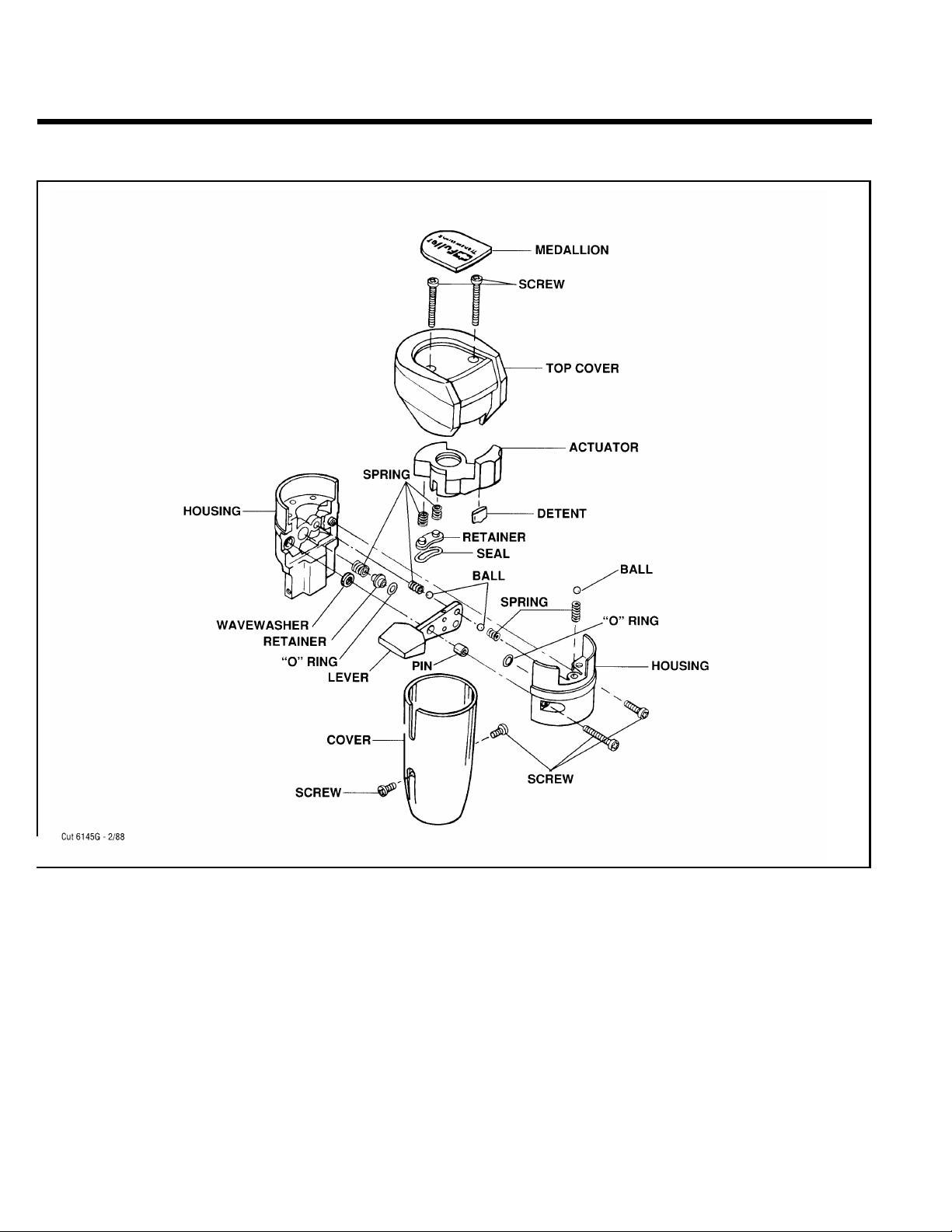
ROADRANGER VALVE A-4900
Removal and Disassembly
1.
Remove two screws holding bottom cover to valve
and slide cover down gearshift lever to expose air
line fittings. Disconnect air lines.
Loosen jam nut and turn control valve from gear
2.
shift lever.
3.
Pry medallion from recess in top cover.
4.
Turn out the two screws to remove the top cover
from valve housing.
Turn out the two screws in side of valve housing to
5.
separate the housing.
Remove the Range Preelection Lever from left
6.
housing and the position balls and guide from
lever.
7. If necessary, remove the spring and O-ring from
bores in left housing.
8. If necessary, remove the springs, O-ring and
sleeve from bores in right housing.
Reassembly and Installation
1.
Refer to the drawing for proper reassembly. Use a
VERY SMALL amount of silicone lubricant on the
O-rings to avoid clogging ports. A small amount of
grease on the position springs and balls will help
to hold them in place during reassembly
2.
Install control valve on gear shift lever and tighten
jam nut.
Attach air lines and install bottom cover.
3.
24
—
Page 28
AIR SYSTEM
SPLITTER SHIFT
AIR SYSTEM:
Operation
In addition to the various components of the Range Shift Air
System, the Splitter Shift Air System utilizes a splitter cylin-
der and the Roadranger Valve A-4900. See Air System
Schematics.
CONSTANT AIR from the air filter/regulator assembly is
supplied to the splitter cylinder at the port on right side of
cylinder cover. The Insert valve installed in cover (see
page 27) provides the proper air flow needed to move the
splitter piston in the cylinder (rearward to engage rear auxiliary drive gear for operation in direct; forward to engage the
front auxiliary drive gear for operation in overdrive).
WHILE IN HI OR LO RANGE, AIR needed to make the
splitter selection and complete the shift is supplied to the
Roadranger valve from the tee fitting at the HI RANGE or
“H” port of the slave valve. When the overdrive selection is
made, the AIR passes through the Roadranger valve and is
supplied to the Left Port of cylinder cover.
With Splitter Control Button in the “DIRECT’’/REARWARD position, the “SP” Port of the Roadranger valve is
CLOSED and NO AIR is supplied to the Left Port of the
Splitter cylinder cover.
Trouble Shooting
If the transmission fails to shift or shifts too slowly to or from
the ‘(split” position, the fault may be in the Splitter Shift Air
System or related components of the Range Shift Air System.
To locate the trouble, the following checks should be
made with normal vehicle air pressure supplied to the system, but with the engine off.
NEVER WORK UNDER A VEHICLE
WHILE ENGINE IS RUNNING as
personal injury may result from the sudden and unintended movement of vehicle under power. Always
place transmission in the neutral position.
NOTE:
1.
It is assumed that correct PSI readings were
obtained from the air filter/regulator and all air
lines have been checked for leaks.
Air Supply (See Air System Schematics.)
With the gear shift lever in neutral, select HI or LO
RANGE and loosen the connection at the "S“ Port of
the Roadranger Valve until it can be determined that
AIR is supplied to valve. Reconnect air line.
If there is NO AIR, check for a restriction in the air line
between the Roadranger valve and slave valve. Make
sure this line is connected to fitting at the supply Port of
slave valve.
Button REARWARD
(“SP” Port Closed)
While in HI RANGE the button can be moved FORWARD to operate in OVERDRIVE. The "SP” Port of valve is
OPENED when overdrive is selected, supplying AIR to the
Left Port of the Splitter cylinder cover.
Button FORWARD
(“SP” Port Opened)
2.
Roadranger Valve (See Page 24 and Air System
Schematics.)
With the gear shift lever in neutral, disconnect the air
line at the Left Port of splitter cylinder cover, making
sure this line leads from the "SP” Port of the
Roadranger Valve.
A. WHILE IN HI OR LO RANGE, move the Splitter
Control Button FORWARD. There should be AIR
flowing from disconnected line. Move the button
REARWARD to shut off air flow and reconnect air
line.
B. If the preceding conditions do not exist, the
Roadranger valve is defective, or there is a restric-
tion in the air lines.
Splitter Cylinder. (Refer to the following illustra-
3.
tion.)
If any of the seals in the splitter cylinder assembly are
defective, the splitter shift will be affected. The degree
of air lost will govern the degree of failure, from slow
shifting to complete shift failure.
A. Leak at O-ring A results in a slow shift to engage
rear auxiliary drive gear; pressurizing of transmis-
sion case; auxiliary gearing can be disengaged.
25
Page 29
AIR SYSTEM
B. Leak at O-ring B results in slow shifting or
complete failure to engage and disengage
front or rear auxiliary drive gearing; steady
flow of air from exhaust port of Roadranger
valve and/or cylinder cover when Splitter Control Button is in the REARWARD position.
C. Leak at gasket C results in a slow shift to dis-
engage rear auxiliary drive gear; steady flow
of air to atmosphere.
4. Insert Valve (See Page 27).
Any constant flow of air from exhaust port of cyl-
inder cover usually indicates a faulty insert valve.
Exhaust should occur ONLY BRIEFLY when Splitter Control Button is moved REARWARD WHILE
IN LO and HI RANGE.
A faulty insert valve, leaking at the O-rings of
valve O.D. or from inner seals results in constant
air leak and shift failure. Two indications of defective O-rings or seals are:
A. CONSTANT AIR flowing from exhaust port of
cylinder cover.
B. CONSTANT AIR flowing from Exhaust Port
“E” of control valve WHILE SPLITTER CON-
TROL BUTTON IS REARWARD OR FORWARD
(providing the control valve is operating pro-
perly).
The three O-rings in position on valve O.D. can be
replaced. However, if an inner seal is damaged,
the complete assembly MUST be replaced.
26
Page 30
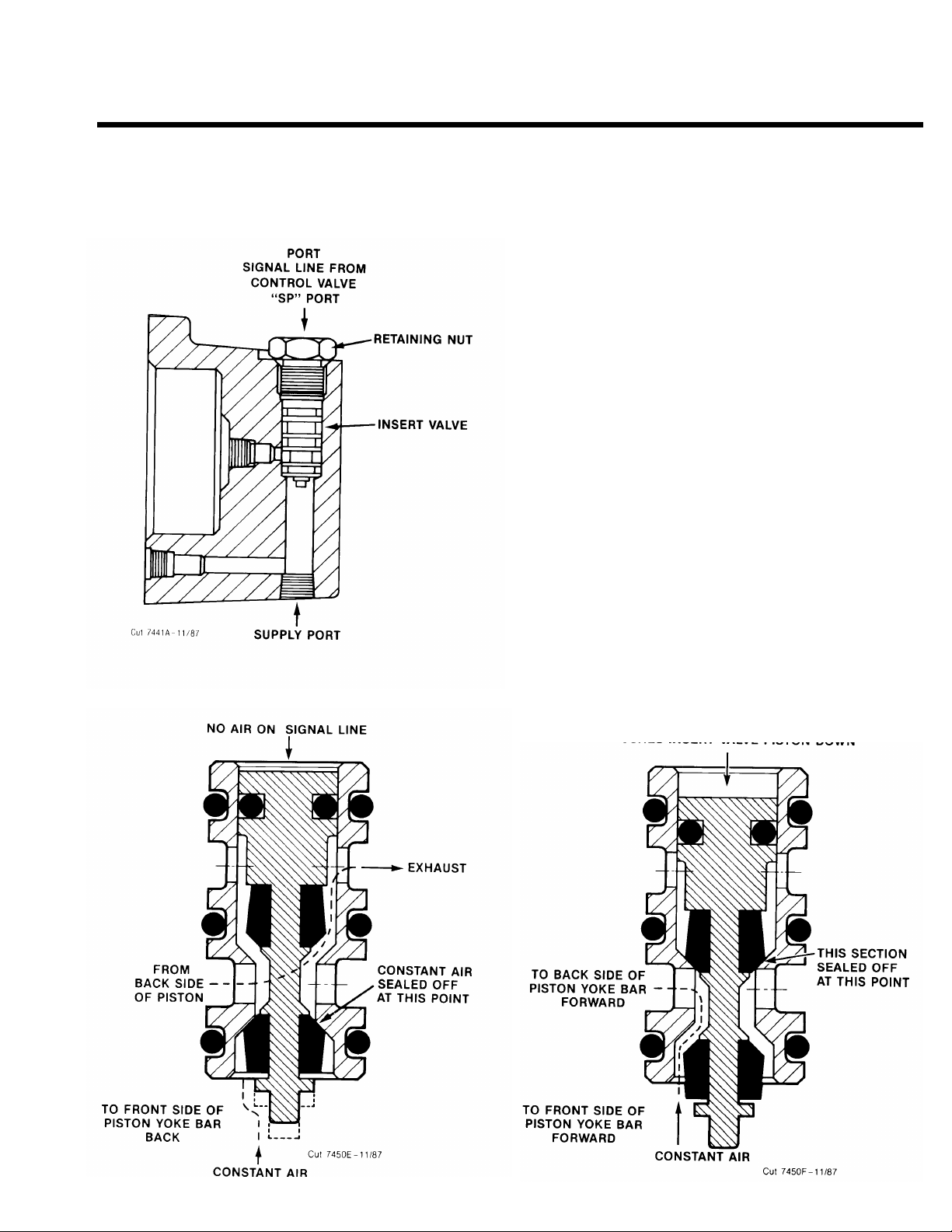
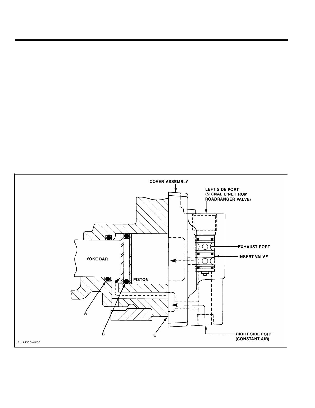
AIR SYSTEM
INSERT VALVE:
(EQUIPPED WITH ROADRANGER VALVE A-4900
The insert valve is a self-contained 1 - 3/16” valve as sembly located in the splitter cylinder cover. It CAN-
NOT be disassembled except for the three O-rings on
outer diameter. The O-rings provide a stationary seal
and do not move in cylinder.
When installing the insert valve in bottom edge of
cover, apply Fuller #71206 silicone lubricant or its
equivalent to O-rings and cylinder walls. Install valve
in bore with flat surface to the outside. When installing the special valve retaining nut, apply Fuller
#71204 adhesive/sealant or its equivalent to threads
and tighten. See TORQUE RECOMMENDATIONS.
Travel of the small insert valve piston is only 3/16”.
As shown in the illustrations below, when NO AIR is
applied to the top side of valve piston, CONSTANT
AIR supplied from the regulator passes to the
FRONTSIDE of cylinder piston, moving the yoke bar
backward to engage the REAR AUXILIARY DRIVE
GEAR (LO RANGE DIRECT AND HI RANGE DIRECT).
The piston moves up to cut off air to the back side of
the cylinder piston. This air is exhausted out the cylinder cover as the piston moves rearward.
When AIR is applied to top side of valve piston,
through signal line, the piston moves down passing
air through the bottom of insert valve to the front and
backside of the cylinder piston, moving the yoke bar
FORWARD engaging the FRONT AUXILIARY DRIVE
GEAR (LO RANGE OVERDRIVE AND HI RANGE
OVERDRIVE).
LOW RANGE AND HIGH RANGE DIRECT
OVERDRIVE
AIR APPLIED THROUGH SIGNAL LINE
PUSHES INSERT VALVE PISTON DOWN
27
Page 31

RTLO-XX613 Models
LO Range
A-4900 Roadranger
Valve
Slave Valve
Identification
Down
Rearward
r
Fule
l
Transmissions
®
H/L
19470 or A-5000
Slave Valve
PS SP
S
H/L
HI
A-5000 Valve
19470 Valve
P
LO
Schematic
Air Filter/Regulator
Assembly
Air from
Vehicle
Source
Splitter Cylinder
Assembly
Constant Air
No Air
SP
Range Cylinder Assembly
Air to
LO
Housing
Port
No Air
HI
System Operation and Schematics—Operation Guide — 3A-21
For all questions
concerning
removal and
replacement,
refer to Eaton
Service and Parts
Literature.
Page 32

RTLO-XX613 Models
HI Range L
A-4900 Roadranger
Valve
Slave Valve
Identification
Schematic
Rearward
r
Fule
l
Transmissions
Up
®
H/L
19470 or A-5000
Slave Valve
PS SP
S
A-5000 Valve
19470 Valve
H/L
HI
P
LO
For all questions
concerning
removal and
replacement,
refer to Eaton
Air Filter/Regulator
Assembly
Service and Parts
Literature.
Air from
Vehicle
Source
3A-22 — Operation Guide—System Operation and Schematics
Splitter Cylinder
Assembly
Constant Air
No Air
SP
Range Cylinder Assembly
No Air
LO
Air to Cover
Port
HI
Page 33

RTLO-XX613 Models
HI Range H
A-4900 Roadranger
Valve
Slave Valve
Identification
Forward
Fule
Transmissions
Up
®
r
l
A-5000 Valve
19470 Valve
PS SP
H/L
19470 or A-5000
Slave Valve
H/L
HI
S
LO
P
Schematic
Air Filter/Regulator
Assembly
Air from
Vehicle
Source
Splitter Cylinder
Assembly
Constant Air
SP
Range Cylinder Assembly
No Air
LO
Air to Cover
Port
HI
System Operation and Schematics—Operation Guide — 3A-23
For all questions
concerning
removal and
replacement,
refer to Eaton
Service and Parts
Literature.
Page 34

DISASSEMBLY SHIFTING CONTROLS
Air System
A. Removal of Air Control
1. Disconnect the two air lines at the "S" or Supply Port
and "P" or End Port of the slave valve on the transmission case.
2.
Remove the air line at the splitter cylinder cover.
NOTE:
bly can now be removed from shift bar housing by
removing the four capscrews from the tower.
If desired, the gear shift lever housing assem-
32
Page 35

DISASSEMBLY SHIFTING CONTROLS
3. Turn out the two mounting screws in the Roadranger
valve cover.
4. Slide the cover down to expose the valve ports and
disconnect the three air lines.
5.Loosen the jam nut and turn the valve and nut from
gear shift lever. Remove the valve cover, air lines
sheathing and O-rings from lever.
6. Disconnect and remove the 1/4" I.D. air line between
Splitter Cylinder and air filter/regulator.
33
Page 36

DISASSEMBLY SHIFTING CONTROLS
7.B.Disconnect and remove the 1/4" I.D. air hoses be-
tween the slave valve (inset) and air filter/regulator
assembly and range cylinder assembly.
Removal of Air
Filter/Regulator Assembly
2.
Turn out the four retaining capscrews and remove slave
valve from transmission case.
3. Remove the hat-type alignment sleeve from bore in
slave valve.
1. Turn out the two capscrews and remove the air filter/
regulator assembly.
NOTE: For disassembly and reassembly of Air Filter/
Regulator Assembly, see Page 23.
34
Page 37

DISASSEMBLY SHIFTING CONTROLS
4. Remove the spring and plunger pin from bore in transmission case. Remove slave valve gasket.
5. If necessary, remove the air line fittings from slave
valve.
NOTE:
Slave Valve Assembly, see Page 23.
For disassembly and reassembly of piston-type
35
Page 38

DISASSEMBLY GEAR SHIFT LEVER
ASSEMBLY
A. Removal
1. Turn out the four retaining capscrews, jar lightly to
break gasket seal and remove the gear shift lever
housing and gasket from shift bar housing.
NOTE: Remote control housings are removed from
shift bar housing in the same manner. For disassembly and reassembly of LRC Assemblies, see 11Iustrated Parts List No. P-541. For disassembly
and reassembly of SRC Assemblies, see illustrated Parts List No. P-515.
and Disassembly
Cut 7288D2/86
2.
Remove the boot from gear shift lever and secure
assembly in vise with bottom of housing up. Use a large
screwdriver to twist between the spring and housing,
forcing the spring from under the lugs in housing.
Do one coil at a time.
36
Page 39

REASSEMBLY GEAR SHIFT LEVER
ASSEMBLY
B. Reassembly of Gear Shift Lever
Housing Assembly
3. Remove the tension spring, washer and gear shift
lever from housing.
4. Remove the spade pin from bore in housing
tower. If necessary, remove the O-ring from
groove inside tower.
1. With the gear shift lever housing secured in vise
as suring disassembly, install the spade pin in
bore of housing tower. If previously removed, install the O-ring in tower groove.
2. Position the gear shift lever in housing with
spade pin in leaver ball slot and install the tension
spring washer over ball, dished-side up.
37
Page 40

REASSEMBLY GEAR SHIFT LEVER
ASSEMBLY
3. Install the tension spring under lugs in housing, seating
one coil at a time. Use of a spring driving tool is
recommended.
4. Remove the assembly from vise and install the
rubber boot over gear shift lever and against
housing.
38
Page 41

DISASSEMBLY AND REASSEMBLY
SHIFT BAR HOUSING
SHIFT BAR HOUSING ASSEMBLY
A. Removal and Disassembly of the Shift
Bar Housing Assembly
For models equipped with an Oil Pump
and/or Cooler Assemblies, make sure to
disconnect the lube line at the fitting on the shift
bar housing before doing the following
instructions.
1. Turn out the retaining capscrews. Jar the top to
break the gasket seal and lift the shift bar housing
from the transmission case. Remove the gasket.
2. Tilt the assembly and remove the three sets of tension springs and balls from the housing bores.
NOTE: During disassembly, lay all parts on a
clean bench in order of removal from the housing
to make reassembly easier. Shift bars not being re-
moved must be kept in the neutral position or the
interlocking parts will lock the bars.
39
Page 42

DISASSEMBLY AND REASSEMBLY
SHIFT BAR HOUSING
3.
Secure the assembly in a vise with the plungerside up. (The front of the housing will be to the
left.) For models so equipped, cut the lockwire
and turn out the retaining capscrews to remove
the oil trough from the housing.
5. Move the 1st-2nd speed shift bar to the housing
rear, removing the yoke and block from the bar. As
the neutral notch in the bar clears the rear boss,
remove the small interlock pin from the bore.
NOTE: Start with the upper shift bar, move all bars
to the right and out the rear boss bore. Cut the
lockwire and remove the Iockscrews from each bar
just before their removal.
4. Move the 3rd-4th speed shift bar to the housing
rear, removing the yoke and block from the bar.
6. Remove the actuating plunger from the center
boss bore.
40
Page 43

DISASSEMBLY AND REASSEMBLY
SHIFT BAR HOUSING
B. Reassembly of the Shift Bar Housing
Assembly.
7.
Move the short LO-Reverse speed shift bar to the
housing rear, remove the yoke from the bar. As the
shift bar is removed from the housing, two 3/4 interlock balls will drop from the rear boss bottom
bore.
1. If previously removed, install the reverse-stop
plunger in the LO-Reverse shift yoke, making sure
the plunger is fully seated in the yoke slot bore.
8. If necessary, remove the plug, spring, and reversestop plunger from the LO-Reverse speed shift
yoke bore.
2. Install the spring in the yoke bore and on the
plunger shank.
41
Page 44

DISASSEMBLY AND REASSEMBLY
SHIFT BAR HOUSING
3. Install the plug and tighten to compress th e
spring (left). Back the plug out 1 - 1 1/2 turns and
stake the plug through the small hole in the yoke
(right.)
5. While holding the plunger shank, install the actuating plunger in the center boss bore.
4.
Secure the shift bar housing in a vise. Hold the
notched-end of the short LO-Reverse speed shift
bar, install the bar in the lower bore of the shift bar
housing bosses.
tighten and wire securely.
NOTE: Start with the lower shift bore of the rear
boss and move to the left (front of the housing).
Keep bars in the neutral position during installation. DO NOT EXCEED the recommended torque
ratings for the yoke Iockscrews as over-tightening
may distort the shift bars.
Install the yoke Iockscrew ,
6. Install one 3/4" interlock ball in the rear boss top
bore. This ball rides between LO-Reverse and 1st2nd speed shift bars.
42
Page 45

DISASSEMBLY AND REASSEMBLY
SHIFT BAR HOUSING
7. While holding the notched-end of the bar, install
the 1st-2nd speed shift bar in the housing boss
middle bore. Position the shift block on the bar between the center and rear bosses, and the yoke on
the bar between the front and center bosses, long
hub to the housing front. Just before inserting the
notched-end of the rear boss bar, install the small
interlock pin VERTICALLY in the neutral notch
bore. Install the block and yoke Iockscrews,
tighten, and lockwire securely.
NOTE: It is necessary that the interlock pin remain in a vertical position during reassembly as
rotation of the bar causes the pin to jam in the tension spring bores.
While holding notched-end of the bar, install the
9.
3rd-4th speed shift bar in the housing boss upper
bore, position the shift block on the bar between
the front and center bosses, long hub to the
housing rear. Install the block and yoke lock-
screws, tighten, and lockwire securely.
10.
For models so equipped, install the oil trough on
the housing. Tighten the capscrews and lockwire
securely.
8. Install the other 3/4" interlock ball in the rear boss
top bore. This ball rides between the 1st-2nd and
the 3rd-4th speed shift bars.
43
Page 46

DISASSEMBLY AND REASSEMBLY
SHIFT BAR HOUSING
11. Remove the assembly from the vise. Install the
three tension balls, one in each bore on the hous-
ing top.
12. Install the three tension springs, one over each
ball in the housing bores.
44
Page 47

REMOVAL - OUTPUT YOKE, AUXILIARY
SECTION,
AND CLUTCH HOUSING
A. Removal Output Yoke
1. Lock transmission by engaging two mainshaft gears
with the mainshaft sliding clutches (inset.) Use a large
breaker bar to turn the output shaft nut from the output
shaft.
2. Pull yoke straight to the rear and off the output shaft.
45
Page 48

REMOVAL - OUTPUT YOKE, AUXILIARY
SECTION, AND CLUTCH HOUSING
B. Removal of the Auxiliary Section
Bar Stock - 3/8" x 1"
Tool Print T-65853
1. Place the transmission in the vertical position. Put
blocks under the clutch housing to prevent damage to
the input shaft. Removal can also be completed in the
horizontal position.
Auxiliary Countershaft Retaining Straps
may be installed to hold countershaft in
place. Auxiliary can be removed without straps use
caution.
3. Install an Auxiliary Countershaft Retaining Strap with
3-3/8" x 1" dean capscrews. Place a flat washer under
the strap to prevent damage to the rear auxiliary countershaft bearing.
Do not use an air gun. Tighten by
hand until the capscrews are snug.
4. Repeat Steps 2 and 3 for the remaining auxiliary countershaft.
2. Remove the four capscrews and the auxiliary countershaft rear bearing cover, gasket, and rear bearing shim.
5. Remove the nineteen capscrews that hold the auxiliary
section to the transmission case.
NOTE:
location.
46
There are three lengths of capscrews, note their
Page 49

REMOVAL - OUTPUT YOKE, AUXILIARY
.
SECTION, AND CLUTCH HOUSING
1. Insert three capscrews in the tapped holes of housing
flange. Tighten evenly to move auxiliary section to the
rear and just far enough from front section to break
gasket seal.
2. Remove capscrews and attach a chain hoist to auxiliary
section. Move the assmbley to the rear until free of front
section and remove gasket.
3. The auxiliary section can also be removed with the
transmission set in the vertical position. Block under the
clutch housing to prevent damage to the imput shaft.
Remove the retaining capscrews from the housing flange
Lift the assembly form the front section. Remove the gasket
47
Page 50

REMOVAL - OUTPUT YOKE, AUXILIARY
SECTION, AND CLUTCH HOUSING
D. Removal Clutch Housing
NOTE: For models so equipped remove the
clutch release mechanism and/or clutch brake
assembly.
1. Remove the six capscrews, six nuts, and six lockwashers form studs that secure the clutch housing to trasmission case.
2. . Jar the clutch housing with a rubber mallet to
break gasket seal and pull from transmission
case. Remove gasket.
48
Page 51

DISASSEMBLY - AUXILIARY
SECTION
A. Removal and Disassembly Rear
Auxiliary Drive Gear and Yoke
1. Cut the lockwire on the splitter yoke retaining bolt and 2. Remove the retaining bolt, splitter yoke and sliding
loosen the bolt.
clutch assembly from the auxiliary section.
49
Page 52

DISASSEMBLY - AUXILIARY
SECTION
AUXILIARY MAINSHAFT
ASSEMBLY
c
SLIDING
CLUTCH
Cut 6593 L-4/87
WASHER
NUT
SPACER
WASHER
b
GEAR
REAR AUXILIARY
DRIVE GEAR
3. Temporarily install an output yoke on the output shaft
and secure it by placing a bar through the yoke.
4. Break loose the 15/16" retaining capscrew on the front
of the output shaft.
50
Page 53

DISASSEMBLY - AUXILIARY
AUXILIARY COUNTERSHAFT
ASSEMBLY
SECTION
Cut 6503M-11/91
B. Removal of the Auxiliary
Countershaft Assemblies
1. Secure the auxiliary housing in a vise. Remove the
auxiliary countershaft retaining straps or rear bearing
covers, shim and rear bearing race.
The countershaft will fall loose in the
auxiliary section.
2. Use a soft bar and maul to partially drive the output
shaft forward.
51
Page 54

DISASSEMBLY - AUXILIARY
C. Removal Rear Auxiliary Drive Gear
Assembly
3. Remove the auxiliary countershaft from the auxiliary
section case.
1. Remove the 15/16" retaining capscrew, retainer and
auxiliary drive gear from the auxiliary section.
SECTION
4. If necessary, secure the countershaft assemblies in a
vise and remove both the front and rear bearings with a
bearing separator and jaw pullers.
52
Page 55

DISASSEMBLYÑ AUXILIARY SECTION
RANGE CYLINDER
ASSEMBLY
Cut 6427-5/83
D. Removal and Disassembly of Range
Cylinder Assembly.
1. Remove the capscrews, range cylinder cover, and
gasket.
*Note: Use lockwire at
this position
2. Remove nut from yoke bar.
53
Page 56

DISASSEMBLY-AUXILIARY SECTION
3. Cut the lockwire. Remove the two 3/4" yoke lockscrews (inset).
4. Pull the yoke bar from the cylinder housing bore.
5. Remove the shift yoke and synchronizer assembly
from output shaft.
6. Remove the range piston from the cylinder bore. If
necessary, remove the O-rings from the position
I.D. and O.D. (inset).
54
Page 57

DISASSEMBLY-AUXILIARY SECTION
7. Remove capscrews and range cylinder housing.
8. If necessary, remove the small O-ring from the
range cylinder housing bore.
55
Page 58

DISASSEMBLY-AUXILIARY SECTION
E. Disassembly Synchronizer Assembly
1.
Place the larger LO range synchronizer ring on the
bench. Cover the assembly with a shop rag to pre-
vent losing the three springs released from the
high range synchronizer at the pin locations. Pull
the HI range synchronizer from the blocker pins.
2. Remove the sliding clutch from the synchronizer
ring LO range pins.
56
Page 59

DISASSEMBLY-AUXILIARY SECTION
F. Removal and Disassembly Output Shaft
and Rear Bearing Assemblies.
1. Use a soft bar and maul to drive the output shaft
forward and through the rear bearing assembly.
2. Remove the bearing inner spacer from the output
shaft.
3. Use the front face of the reduction gear as a base,
press the output shaft through the bearing and
gear. This frees the bearing, LO range gear, and
the splined washer.
4. Remove the stepped washer, LO range gear, and
splined washer from the shaft.
57
Page 60

DISASSEMBLY - AUXILIARY SECTION
G. Removal Splitter Cover
5. Remove the rear bearing retaining capscrews, rear
bearing cover, and gasket from the auxiliary housing.
The rear bearing cone drops from the housing bore
when the cover is removed. If necessary, remove the
oil seal from the cover (inset).
1. Remove the capscrews from the splitter cylinder cover
and remove the splitter cylinder cover and gasket from
the auxiliary section case.
6. Remove the two bearing cups and spacer from the
bearing bore.
2. If necessary, turn out the insert valve retaining nut and
remove insert valve from bore.
58
Page 61

DISASSEMBLY - AUXILIARY
SECTION
3. Pull the yoke bar from cylinder housing. If necessary,
remove the O-ring from piston O.D. (inset).
4. If necessary, remove the small O-ring from the cylinder
housing bore.
59
Page 62

REASSEMBLY-AUXILIARY SECTION
A. Reassembly and Installation of
NOTE: Make sure magnetic plugs preinstalled in
IMPORTANT: Mark timing teeth on the LO Range
1.
gear. A highly visible color of toolmaker's dye is
recommended.
a.
b.
auxiliary housing.
Mark any two adjacent gear teeth on LO Range
gear, front side.
Then mark the two adjacent teeth which are
directly opposite the first set marked. There
should be the same number of teeth between
the markings on each side of the gear.
2. Placed splined washer on output shaft shoulder
facing up as shown.
60
Page 63

REASSEMBLY-AUXILIARY SECTION
3.
Install the LO Range gear on the output shaft,
clutching teeth engaged with the splines down to
engage the washer splines.
5. Using a heat lamp or hot plate and oil heat the output shaft rear bearing and install on output shaft.
Seat the bearing securely on shaft. Bearing can
also be installed using the appropriate driver.
NOTE: DO NOT HEAT BEARING ABOVE 275
o
C).
(136
o
F
4. Install the LO Range gear rear washer on output
shaft and against gear, with chamfer side facing
up.
6. Install the bearing inner spacer on the output
shaft.
61
Page 64

REASSEMBLY - AUXILIARY
SECTION
Place the auxiliary housing on a flat bench and install
7.
the 2 bearing cups and spacer in the rear bearing bore,
the cup with a lip seats next to the rear of the auxiliary
case.
Reassembly Synchronizer Assembly
B.
2. Install the three springs in bores in HI range synchronizer ring.
3. Place the HI range synchronizer ring over pins of L O
speed synchronizer ring, seating springs against pins.
1. Place the larger LO range synchronizer ring face down
on bench with pins up. Place the sliding clutch, recessed side up, on pins of LO range synchronizer.
NOTE: Pins on LO range synchronizer must line up
with chamfered holes on bottom of sliding clutch.
62
Page 65

REASSEMBLY - AUXILIARY
on
C. Installation of Auxiliary Driver Gear.
4.
Apply downward pressure to the HI range synchronizer
ring WHILE TWISTING COUNTER-CLOCKWISE to
compress the springs and fully seat ring on blocker pins
of LO range synchronizer. It is suggested that a shop
towel be placed over the synchronizer to prevent injury
to your hands.
1. Place auxiliary drive gear, retainer and Òk capscrew
output shaft assembly. Secure capscrew on shaft till
tight, recommended torque will be applied during final
assembly (pg. 67)
SECTION
5. Install synchronizer assembly to front of output shaft
assembly.
D. Reassembly of Auxiliary
Countershaft Assemblies and
Timing.
To make reassembly of the auxiliary section easier, you can
make this auxiliary section fixture out of a section of 2 x 12.
63
Page 66

REASSEMBLY - AUXILIARY
SECTION
NOTE:
at this time if replacement was required.
1. Mark each countershaft for correct timing. Locate the
"O" stamped on the countershaft and mark the tooth
with highly visible toolmakers dye or paint.
Auxiliary countershaft bearings will be installed
3. Install the range yoke into the synchronizer sliding
clutch slot, offset side facing down.
4. Place the auxiliary housing over countershaft assemblies and output shaft assemblies.
2.
Place the countershaft in fixture or on a flat surface for
reassembly. Locate output shaft assembly between
countershaft, timing of the auxiliary will be checked at
this time. The single marked tooth of each countershaft
must align with the two teeth marked on each side of
the LO range gear,
64
Page 67

REASSEMBLY - AUXILIARY
E. Reassembly Range Cylinder
5. Heat the rear output shaft bearing cone and install the
bearing on the shaft taper side down.
SECTION
NOTE:
6. Install the rear bearing cover on the auxiliary housing.
The nylon collar and brass washer are installed in the
chamfered hole on the lower right side of the cover.
NOTE: Because the collar becomes distorted when
compressed, DO NOT REUSE OLD NYLON COLLAR.
Do not heat the bearing above 275oF (136oC).
1. Install O-ring in slot of small bore in cylinder. Apply
silicone to all O-rings (inset).
2. If previously removed, install the O-rings in the I.D. and
O.D. of the range position.
65
Page 68

REASSEMBLY - AUXILIARY
F. Reassembly and Installation
of Splitter Cylinder Assembly
3.4.Position new gasket on housing. Install range cylinder,
piston yoke, piston and retaining nut into housing.
Tighten retaining nut to recommended torque. Install 4
capscrews into range cylinder housing and tighten to
recommended torque.
SECTION
Place range cylinder cover and new gasket on range
cylinder, install 4 capscrews and tighten to recommended torque.
1. If previously removed, install the small O-ring in the
cylinder housing bore.
2. If removed, install the O-ring on the piston O.D. (left).
Insert the yoke bar in the cylinder housing bore (right).
66
Page 69

REASSEMBLY - AUXILIARY
G. Reassembly of Auxiliary Rear
Bearing Assembly
1.
Place the rear bearing cone over the bearing and into
the rear bore. Align the .100 shim over the cone and
install the rear bearing cover with 4 capscrews tighten
only till snug (right). Retaining straps may also be used
at this time they are required for horizontal installation.
3.
If previously removed, install the insert valve, flat end to
the outside, and the valve retaining nut in the bottom
bore of the cylinder cover. Tighten to recommended
torque ratings.
NOTE: Prior to installation of the insert valve, make
sure the three O-rings on the valve O.D. are not defective. Replace, if necessary.
Complete assembly by installing remaining rear bearing cover (left).
Installation of Range Yoke
H.
Capscrews and Recommended
Torque of Auxiliary Drive Gear Nut
SECTION
4. Place the new splitter cylinder gasket, splitter cylinder
assembly, new splitter cylinder cover gasket and splitter cylinder cover onto the auxiliary housing. Install 4
capscrews into the assembly and tighten to recommended torque.
67
1.
Install the 2 capscrews into the range yoke and tighten
to recommended torque (right). Tighten auxiliary drive
gear retaining nut to recommended torque (left).
Page 70

REASSEMBLY - AUXILIARY
I. Installation of Splitter Sliding Clutch
and Yoke
1. Place splitter shift yoke into splitter sliding clutch slot.
Install assembly onto auxiliary section engaging the
sliding clutch teeth into the suxiliary drive gear clutching
teeth and splitter yoke onto yoke bar align lockscrew
tighten to recommended torque and lockwire.
SECTION
68
Page 71

DISASSEMBLY - FRONT
SECTION
AUXILIARY DRIVE GEAR
ASSEMBLY
Cut 6417 L-3/87
A. Removal Front Auxiliary Drive Gear
1. Cut lockwire from auxiliary bearing retainer ring
capscrews.
*Note: Use lock wire at
this position
2. Remove snap ring from mainshaft rear groove.
69
Page 72

DISASSEMBLY - FRONT
SECTION
3. Remove the splined washer from inside front auxiliary
drive gear assembly.
4.
Remove six capscrews from the auxiliary bearing retainer ring. Insert three puller screws in the specially
tapped holes of retainer ring. Tighten screws evenly to
pull the front auxiliary drive gear assembly from case
bore.
5. Remove front auxiliary drive gear from mainshaft.
6. Remove the spline d washer from the mainshaft also
remove the front auxiliary drive gear retaining snap ring
from the mainshaft.
70
?
Page 73

DISASSEMBLY-FRONT SECTION
Cut 6382-9/80
B. Removal and Disassembly of Left
Reverse Idler Gear Assembly
1. Move the mainshaft reverse gear as far to the rear
as possible and remove the snap ring from I.D. of
gear.
2. Move the reverse gear forward and against the LO
speed gear, engaging the splines of mainshaft
sliding clutch.
71
Page 74

DISASSEMBLY - FRONT
SECTION
3. Using inside jaw pullers or impact puller, remove the
auxiliary countershaft front bearing race from left
reverse idler gear bore. If necessary, repeat the
procedure for removing the auxiliary countershaft front
bearing race from right reverse idler gear bore.
4. Loosen the nut on the idler shaft, (inset). Remove the
stop nut and washer from front of idler shaft.
5. Remove the pipe plug from rear of idler shaft and use
an impact puller, 1/2"-13 threaded end, to remove shaft
from case bore (inset).
6. As the idler shaft and idler plate are moved to the rear,
remove the thrust washer, and gear from case. If necessary, remove the inner race from bearing and
remove needle bearing from idler gear.
72
Page 75

DISASSEMBLY-FRONT SECTION
c.
Removal of Countershaft Bearings
NOTE: In the following instructions, the front
and rear bearings from BOTH countershaft are
removed. For removal of the mainshaft assembly
from case, it is necessary to remove the bearings
from right countershaft ONLY.
1. Temporarily reinstall front auxiliary drive gear on
mainshaft, remove snap ring from each counter-
shaft rear groove.
2. Remove six capscrews from front bearing cover.
3. Remove front bearing cover.
4. From inside the case, use a soft bar and maul to
drive the countershaft rear bearings to the rear
and from case bores.
NOTE: This procedure will damage the bearings
and should not be attempted unless replacement
of the bearings is planned.
73
Page 76

DISASSEMBLY-FRONT SECTION
5. Turn out the capscrew and remove the front
bearing retainer plate from each countershaft.
7. From the case rear, use a soft bar and maul to
drive each countershaft forward to unseat the
front bearings from case bores and expose the
bearing snap rings.
8. Use a bearing puller or pry bars to remove the
countershaft front bearings.
6. Use a soft bar and maul to drive each countershaft
to the rear as far as possible. This will partially unseat the front bearings.
NOTE: The soft bar used should have a flattened
end that is large enough so as not to damage
holes for roll pin and capscrew.
NOTE: The bearing inner race of models equipped
with roller-type front bearings will remain pressed
on countershaft.
74
Page 77

DISASSEMBLY-FRONT SECTION
D. Removal and Disassembly of Mainshaft
Assembly
1. Block the right countershaft assembly against
case wall and pull the mainshaft assembly to the
rear to free pilot from input shaft pocket. Tilt front
of mainshaft up and lift the assembly from case
(inset). Use caution as the reverse gear is free and
can fall from shaft.
2. Remove the 3rd-4th speed sliding clutch from
mainshaft front.
75
Page 78

DISASSEMBLY-FRONT SECTION
Remove the reverse gear and spacer from main-
3.
shaft rear.
4. From mainshaft rear, pull the key from mainshaft
key way.
NOTE: When removing limit washers, spacers and
gears, note their location on mainshaft to facilitate reassembly. Keep the internal-splined
washers and external-splined spacers with the
gear from which they were removed. There is
ONLY one limit washer and one spacer belonging
to each gear.
5. Turn the reverse gear limit washer to align its
splines with those of the mainshaft and remove
washer.
6. Remove the LO-Reverse speed sliding clutch from
mainshaft.
76
Page 79

DISASSEMBLY-FRONT SECTION
7.
Using a small screwdriver, turn the limit washer in
hub of LO speed gear to align its splines with
those of the mainshaft. Pull the LO speed gear
from rear of mainshaft to remove limit washer,
spacer, and gear. If necessary, remove the snap
ring from I.D. of gear (inset).
Remove each remaining gear, limit washer, spacer,
8.
and sliding clutch from mainshaft in the same
manner previously detailed. And, if necessary, remove the snap ring from I.D. of each gear.
77
Page 80

DISASSEMBLY-FRONT SECTION
DRIVE GEAR
ASSEMBLY
E. Input Shaft Removal
1. Remove the bearing retaining snap ring from
groove in shaft.
2. Use a rubber maul on the input shaft to cock the
bearing in bore.
78
Page 81

DISASSEMBLY-FRONT SECTION
5. Remove drive gear spacer, and snap ring (inset).
3. Drive input shaft toward rear of transmission,
through bearing as far as possible. Pull input
shaft.
4. Use pry bars or screwdriver to complete removal
of bearing.
6. Pull input shaft forward and out of drive gear and
case.
79
Page 82

DISASSEMBLY-FRONT SECTION
8. Remove main drive gear from case.
7. Check the bushing in pocket of input shaft, re-
place if worn.
80
Page 83

DISASSEMBLY - FRONT
SECTION
F. Removal and Disassembly of
Countershaft Assemblies
NOTE: Except for the PTO gears, the left and right
countershaft assemblies are identical and disassembled in the same manner.
1.
Move the right countershaft assembly to the rear as far
as possible so front of shaft can be removed from case
bore and moved to the center of the case. Lift the
assembly from case and repeat the procedure for left
countershaft assembly.
NOTE:
are identical and disassembled in the same manner. If
removal and disassembly of this assembly is necessary, refer to Part B of this section.
The left and right reverse idler gear assemblies
. .
2. Remove the drive gear retaining snap ring from front of
each countershaft.
81
Page 84

DISASSEMBLY - FRONT
SECTION
3. Use the rear face of 3rd speed gear as a base, press
the drive gear, PTO gear, and 3rd speed gear from
each countershaft. This removes the front bearing inner
race from the countershaft.
IMPORTANT: NEVER USE THE PTO GEAR AS A
PRESSING BASE. The narrow face width of this gear
makes it very susceptible to breakage.
4.G.Disassembly is complete at this point due to the welded
countershaft design. Replacement of reverse, low first
and 2nd speed gears will be completed as an assembly
gears are not available separately.
Removal and Disassembly of Right
Reverse Idler Gear Assembly
NOTE:
see section B. The right and left reverse idler gear
assemblies are disassembled in the same manner.
To remove the right reverse idler gear assembly
82
Page 85

DISASSEMBLY-FRONT SECTION
H. Removed and Disassembly of Integral
Oil Pump
2. Remove three Allen head capscrews and washers
that retain the integral oil pump to front of case.
1. Straighten Iocktang on suction tube (inset), remove suction tube from oil pump. If necessary remove O-ring from suction tube.
83
Page 86

DISASSEMBLY-FRONT SECTION
3. Remove the integral oil pump from case.
4. Remove integral oil pump retainer plate from case.
5. Remove outer oil pump element from pump.
6. Remove drive gear retaining snap ring from drive
shaft.
84
Page 87

DISASSEMBLY-FRONT SECTION
7. Remove drive gear from pump drive shaft
8. Remove key from drive shaft keyway.
9. Remove element retaining snap ring from drive
shaft.
10.
Remove internal oil pump element from drive
shaft.
85
Page 88

DISASSEMBLY-FRONT SECTION
.
11. Remove two keys from drive shaft keyways.
14. Remove relief valve from housing bore.
12. Remove the drive shaft from integral oil pump
housing. If necessary, remove rear drive gear re-
tention snap ring from drive shaft.
13.
Remove relief valve roll pin from pump housing,
relief valve spring can now be removed from reIief valve housing bore (inset).
86
15.
If necessary front case plug can be removed from
case by driving the plug through front of case.
Remove O-ring from O.D. of plug if necessary.
Page 89

DISASSEMBLY-FRONT SECTION
1. Disassembly Auxiliary Drive Gear
Assembly
1. Remove the snap ring from hub of front auxiliary
drive gear.
3. If necessary, remove the O-rings from hub O.D. of
front auxiliary drive gear.
2. Using the rear face of retainer ring as a base,
press the drive through bearing.
87
Page 90

REASSEMBLY-FRONT SECTION
,
1. If previously removed, install the O-rings on
extended front hub of front auxiliary drive gear.
2. Install the retainer ring on front auxiliary drive
gear, snap ring groove facing front hub and away
from gear teeth.
3. Start the front auxiliary drive gear bearing on front
hub, bearing snap ring facing groove in retainer
ring. Using both hands, press the bearing on gear
with snap ring in groove of retainer ring (inset).
4. Install the snap ring in groove of front gear hub to
retain bearing.
88
Page 91

REASSEMBLY-FRONT SECTION
B. Reassembly and Installation of Integral
Oil Pump
1. Replace O-ring on front case plug. Seat plug in
front case bore with a maul.
2. Install relief valve in intergral oil pump housing as
shown.
3. Install relief valve spring in oil pump housing.
4. Secure oil pump housing in a vice. Depress spring
in housing bore and drive relief valve retention roll
pin into roll pin bore.
89
Page 92

REASSEMBLY-FRONT SECTION
5. If removed replace drive shaft snap ring on pump
drive shaft and insert drive shaft through pump
housing bore as shown.
Install two keys on drive shaft (inset), and install
6.
integral oil pump inner element on drive shaft,
aligning keys on drive shaft with keyways on inner
element.
7.
Install inner element retention snap ring in drive
shaft snap ring groove.
Install drive gear key in keyway of drive shaft (in-
8.
set), install drive gear on drive shaft aligning keyway on drive gear with key on drive shaft.
NOTE: Place round key in the round keyway;
square key in the square keyway.
90
Page 93

REASSEMBLY-FRONT SECTION
9. Install outer drive gear retention snap ring in
groove of drive shaft.
10. Install outer integral oil pump element over inner
element.
11. Install integral oil pump retainer over alignment
pin inside of case, bore in retainer facing rear of
case.
12. Install integral oil pump assembly in case aligning front face of oil pump with retainer and alignment pin.
91
Page 94

REASSEMBLY-FRONT SECTION
13. Install three capscrews and washers through
front of case and into pump housing, tighten
capscrews to recommended torque.
. . .
14. Replace O-ring on suction tube and install tube
under case rib and into integral oil pump. Bend
Iocktang of suction tube over case rib.
92
Page 95

REASSEMBLY - FRONT SECTION
CASE ASSEMBLIES
NOTE: Before starting reassembly, make sure the three
magnetic discs are solidly in place at bottom of case. These
can be secured to disc mounting surfaces with Scotch Grip
Rubber Adhesive or equivalent adhesive.
C. Reassembly and Installation of Right
Reverse Idler Gear Assembly
2. Install the bearing inner race on idler shaft and insert
shaft into case bore, threaded-end of shaft to the front.
As the idler shaft is moved forward, install the reverse
idler gear on shaft, long hub to the front and seating on
bearing inner race. Position the thrust washer on shaft
between the gear and support boss in case and continue with movement of idler shaft forward into bore of
Support boss.
1. If previously removed, thread pipe plug in rear of reverse idler shaft and tighten. Install the thrust washer to
the end of the idler shaft.
NOTE:
ing into bore of reverse idler gear.
If previously removed, replace the needle bear-
3. Making sure that the reverse idler shaft is seated in
bore of support boss and forward as far as possible,
install the washer and stop nut on front of shaft. Tighten
nut to recommended torque rating.
93
Page 96

REASSEMBLY - FRONT
D. Reassembly of Countershaft
SECTION
Assemblies
NOTE: Except for the PTO gears, the left and right
countershaft assemblies are identical and reassembled
in the same manner.
4.
Install the OUTER RACE of auxiliary countershaft front
bearing into case bore.
NOTE:
of auxiliary countershaft and never with outer race.
The bearing INNER RACE is installed on front
NOTE:
of the shaft and are note serviceable.
Reverse low, 1st and 2nd speed gears are part
1.
Press the 3rd speed gear on the countershaft, long hub
of gear to countershaft front.
94
Page 97

REASSEMBLY - FRONT SECTION
4. Install the drive gear retaining snap ring in groove on
front of each countershaft.
2. Start the PTO gear onto countershaft, bullet-nose side
of teeth facing up and toward rear of shaft. Align keyway of drive gear with key in countershaft and press
BOTH gears onto shaft, long hub of drive gear against
PTO gear.
NOTE:
PTO gear; the right countershaft assembly has a 45-
tooth PTO gear.
The left countershaft assembly has a 47-tooth
5.
Use a flanged-end driver to install bearing inner race on
countershaft, shoulder of race against shoulder of countershaft.
3. To avoid confusion during installation, mark the end of
left countershaft with an "L", the end of right countershaft with an "R".
95
,
Page 98

REASSEMBLY - FRONT
IMPORTANT: Mark the countershaft drive gear for timing
purposes. On the drive gear of each countershaft assembly, mark the tooth aligned with keyway of gear and
stamped with an "O" for easy identification. A highly visible
color of toolmakers' dye is recommended for making timing
marks.
SECTION
E. Partial Installation of Countershaft
1. Place the left countershaft assembly into position in
case, making sure that the "L"-marked assembly has
the larger 47-tooth PTO gear. Place the right countershaft assembly into position in case, making sure that
the "R"-marked assembly has the smaller 45-tooth PTO
gear.
Assemblies
96
Page 99

REASSEMBLY-FRONT SECTION
F. Bearing Installation of Left Countershaft
Assembly
1. Move the left countershaft assembly to the rear
and insert countershaft support tool or blocking
to center shaft in rear case bore.
2.
Use a flanged-end bearing driver to start the
bearing in case bore.
NOTE: The inner race of roller-type front bearing
is pressed on front of countershaft.
3. Center the front of left countershaft in bearing and
move the assembly forward.
4. Use a flanged-end bearing driver to completely
seat front bearing or bearing outer race in case
bore.
97
,...
Page 100

REASSEMBLY-FRONT SECTION
G. Reassembly, Installation and Timing of
Main Drive Gear Assembly
5. Position the retainer plate on front of left countershaft,
roll pin in hole at end of shaft, and secure with capscrew
tightening to recommended torque.
1. Install the snap ring in I.D. of main drive gear.
6. Remove countershaft support tool or blocking
from rear case bore and install the left counter-
shaft rear bearing with larger I.D. lead chamfer to
the front of shaft and install the snap ring in
groove at rear of left countershaft.
Mark the main drive gear for timing purposes.
2.
Mark any two adjacent teeth on drive gear and repeat the procedure for the two adjacent teeth
directly opposite the first set marked. A highly visible color of toolmakers' dye is recommended for
making timing marks.
98
 Loading...