Danfoss RAV 10/8, RAV 15/8, RAV 25/8, RAV 20/8, VMT 15/8 Data sheet
...
Data sheet
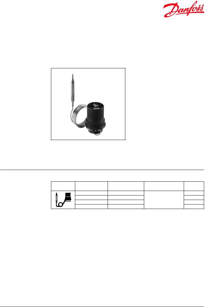
Thermostatic actuator RAVV
- for 2-way valves RAV-/8 (PN 10), VMT-/8 (PN 10), VMA (PN 16)
Description
RAVV is self-acting thermostatic actuator primarily for use for temperature control in small hot water cylinders and to control flow temperatures in central heating systems.
RAVV can be combined with 2-way valves RAV-/8, VMT-/8 or VMA 15. Controller closes on rising temperature.
There is a special version with a section of the capillary tube coiled up to function as minimum temperature sensor. This version can be used to control air heating coils.
Main data:
•DN 10-25
•kv 0,4-1,6 m3/h
•PN 10 with RAV-/8 and VMT-/8 valves PN 16 with VMA valves
•Setting ranges:
10 … 38 °C / 27 … 57 °C / 40 … 70 °C
•Temperature:
- Circ. water / glycolic water up to 30 %:
2 … 120 °C with RAV-/8 and VMT-/8 valves 2 … 130 °C with VMA valves
•Connections:
- Internal and external thread
•Flow mounting
Ordering
Example:
Temperature controller, DN 15,
kv 1,6; PN 16; setting range 27 … 57 °C;
Tmax 130 °C; 2-way valve with ext. thread;
-1× RAVV thermostatic actuator, 27-57 °C
Code No: 013U1252
-1× VMA DN 15 valve
Code No: 065F2034
Option:
-1× Imm. pocket, brass Code No: 017-4370
-1× Weld-on tailpieces Code No: 003H6908
RAVV thermostatic actuator
Picture |
Setting range |
Capillary tube lenght |
Max. sensor temperature |
Code No.1) |
|
(°C) |
(m) |
(°C) |
|||
|
|
||||
|
10 … 38 |
1,5 |
|
013U1255 |
|
|
10 … 38 |
5,02) |
120 |
013U1253 |
|
|
27 … 57 |
1,5 |
013U1252 |
||
|
|
||||
|
40 … 70 |
1,5 |
|
013U1251 |
1)Incl. Rp ½ sensor stuffing box
2)Effective lenght including minimum temperature sensor
Valves
Picture |
Type |
DN |
kv1) |
PN |
Connection |
Code No. |
||
(mm) |
(m3/h) |
inlet |
outlet |
|||||
|
|
|
|
|||||
|
RAV 10/8 |
10 |
1,1 |
|
Rp 3/83) |
R 3/83) |
013U0012 |
|
|
RAV 15/8 |
15 |
1,2 |
|
Rp 1/23) |
R 1/23) |
013U0017 |
|
|
RAV 20/8 |
20 |
1,5 |
|
Rp 3/43) |
R 3/43) |
013U0022 |
|
|
RAV 25/8 |
25 |
1,6 |
10 |
Rp 13) |
R 13) |
013U0027 |
|
|
VMT 15/82) |
15 |
1,2 |
|
G 3/4 A4) |
G 3/4 A4) |
065F0115 |
|
|
VMT 20/82) |
20 |
1,5 |
|
G 1 A4) |
G 1 A4) |
065F0120 |
|
|
VMT 25/82) |
25 |
1,6 |
|
G 1 1/4 A4) |
G 1 1/4 A4) |
065F0125 |
|
|
|
|
0,4 |
|
|
|
065F2031 |
|
|
|
|
0,6 |
|
|
|
065F2032 |
|
|
VMA 155) |
15 |
0,8 |
16 |
G 3/4 A4) |
G 3/4 A4) |
065F2033 |
|
|
|
|
1,1 |
|
|
|
065F2034 |
|
|
|
|
1,7 |
|
|
|
065F2035 |
|
1)The capacity (kv ) applies to a P-band of 6 °C. Other P-band, see “Technical data”.
2)For ordering of Cu fittings, see Accessories.
3)According to ISO 7/1
4)According to ISO 228/1
5)For ordering ext. thread tailpieces, see Accessories.
DEN-SMT/SI |
VD.52.O7.02 © Danfoss 03/2014 |
1 |

Data sheet |
Thermostatic actuator RAVV |
|
|
|
|
|
|
|
|
|
|
|
|
|
|
|
|
Ordering (continuous) |
Accessories for thermostat |
|
|
|
|
|
|
|
|
|
|
|
|
|
|
|
|
|
Picture |
Type designations |
|
|
Connection |
|
Code No. |
|
|
|
Immersion pocket |
Rp ½ × M14 × 1mm, brass, Ø 11 × 112 mm |
|
017-4370 |
|||
|
|
Rp ½ × M18 × 1,5mm; stainlees steel Ø 11 × 112 mm |
|
017-4369 |
||||
|
|
|
|
|||||
|
|
Sensor stuffing box |
R ½ × M14 × 1 mm; rubber EPDM Ø 12,6 × 2,5 × 6 mm |
|
013U02921) |
|||
|
1) Code includes housing, gasket, 4 washers and sealing bolt |
|
|
|
|
|||
|
Accessories for valves |
|
|
|
|
|
|
|
|
|
|
|
|
|
|
|
|
|
Picture |
Type designations |
|
For valve |
Dimensions |
|
Code No. |
|
|
|
|
|
|
Ø 15 × 1 |
|
|
013G4125 |
|
|
|
|
VMT 15 |
Ø 16 × 1 |
|
|
013G4126 |
|
|
Compression fittings1),2),3) |
|
|
Ø 18 × 1 |
|
|
013G4128 |
|
|
|
VMT 20 |
Ø 18 × 1 |
|
|
013U0134 |
|
|
|
|
|
|
|
|||
|
|
|
|
Ø 22 × 1 |
|
|
013U0135 |
|
|
|
|
|
|
|
|
||
|
|
|
|
VMT 25 |
Ø 28 × 1 |
|
|
013U0140 |
|
|
Weld-on tailpieces |
|
|
- |
|
|
003H6908 |
|
|
External thread tailpieces |
|
VMA 15 |
Con. ext. thread acc. to EN |
|
R ½ “ |
003H6902 |
|
|
|
|
10226-1 |
|
|||
|
|
|
|
|
|
|
|
|
|
|
Valve stuffing box3) |
|
RAV/VMT/VMA |
|
|
|
065F0006 |
1)Compression fitting consist of compression ring and union
2)For copper pipe
3)The products can only be ordered in multiple packing containing 10 pieces each
Technical data |
|
|
|
|
|
|
|
|
|
|
|
|
|
|
|
|
|
|
|
|
|
|
Max. |
|
Max. |
|
Max. |
Max. |
|
|
Type RAVV- |
kV (m3/h) for a P-band in °C of |
working |
|
diff. |
|
test |
flow |
||||||
|
|
|
|
|
|
|
|
pressure |
|
pressure |
|
pressure |
temp. |
|
|
|
|
|
|
|
|
|
|
|
|
||||
|
|
2 |
4 |
6 |
|
8 |
10 |
12 |
(bar) |
|
(bar) |
|
(bar) |
(°C) |
|
RAV 10/8 |
0,6 |
0,8 |
1,1 |
|
1,2 |
1,3 |
1,4 |
|
|
|
|
|
|
|
RAV or VMT 15/8 |
0,6 |
0,9 |
1,2 |
|
1,3 |
1,5 |
1,6 |
10 |
|
0,8 |
|
16 |
120 |
|
RAV or VMT 20/8 |
0,7 |
1,2 |
1,5 |
|
1,8 |
2,1 |
2,3 |
|
|
||||
|
|
|
|
|
|
|
|
|||||||
|
RAV or VMT 25/8 |
0,7 |
1,2 |
1,6 |
|
2,0 |
2,3 |
2,6 |
|
|
|
|
|
|
|
VMA 15 (kVS = 0,4) |
0,2 |
0,3 |
0,4 |
|
|
|
|
|
|
51) |
|
|
|
|
VMA 15 (kVS = 0,63) |
0,3 |
0,5 |
0,6 |
|
|
|
|
|
|
|
|
|
|
|
VMA 15 (kVS = 1,0) |
0,4 |
0,7 |
0,8 |
|
|
|
|
16 |
|
21) |
|
25 |
130 |
|
VMA 15 (kVS = 1,6) |
0,4 |
0,8 |
1,1 |
|
|
|
|
|
|
|
|
|
|
|
VMA 15 (kVS = 2,5) |
0,7 |
1,2 |
1,7 |
|
|
|
|
|
|
11) |
|
|
|
|
Materials |
|
|
RAV/VMT |
|
|
|
|
VMA |
|
|
|||
|
Valve body |
|
|
Brass |
|
|
|
|
DZR |
|
|
|||
|
Valve cone |
|
|
NBR rubber |
|
|
|
|
EPDM |
|
|
|||
|
Spindle |
|
|
|
- |
|
|
|
|
DZR |
|
|
||
|
Temperature sensor |
|
|
|
|
|
|
|
|
Cu |
|
|
||
|
Immersion pocket |
|
|
|
|
|
|
|
Brass or stainless steel |
|
|
|||
|
Capillary tube |
|
|
|
|
|
|
|
|
Cu |
|
|
||
1) In installations requiring a low-noise function the differential pressure is not to exceed 1 bar.
2 |
VD.52.O7.02 ©©Danfosss06/201503/2014 |
DEN-SMT/SI |

Data sheet |
Thermostatic actuator RAVV |
|
|
Application principles
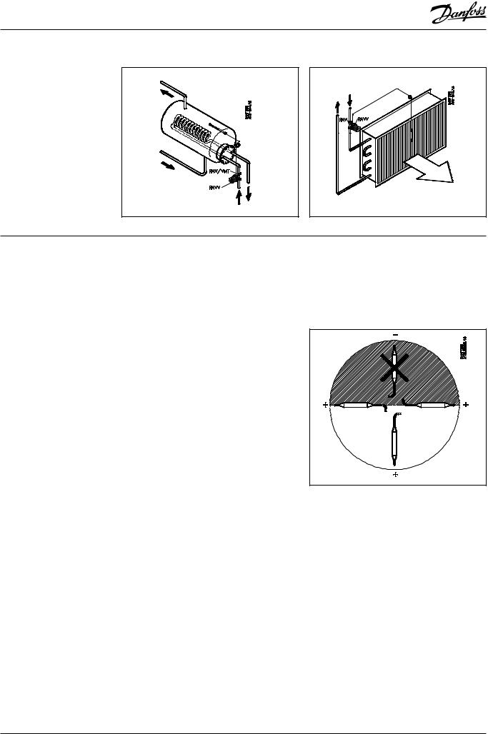
The actuator RAVV must be installed in the flow pipeline only.
Hot water cylinder |
Air heating coil |
Installation positions |
Temperature controller |
|
The valve body must be installed in the flow |
|
pipeline with the flow in the direction indicated |
|
by the cast-in arrow. |
|
The flow temperature must be min. 15 °C higher |
|
than the set closing temperature. |
Temperature sensor
The sensor must be installed in position from horizontal to vercally down.
The sensor must always be placed in a pocket when the temperature is to be measured directly in a medium.
DEN-SMT/SI |
VD.52.O7.02 © Danfoss 03/2014 |
3 |
 Loading...