


TABLE OF CONTENTS |
|
1. PRECAUTION ................................................................................................................................... |
2 |
2. GENERAL SPECIFICATIONS ......................................................................................................... |
3 |
3. NAMES OF MAJOR COMPONENTS............................................................................................. |
4 |
4. FUNCTION OF MAIN COMPONENTS ........................................................................................... |
5 |
5. GENERAL INFORMATIONS............................................................................................................ |
6 |
6. CARE AND MAINTENANCE........................................................................................................... |
7 |
7. TROUBLE SHOOTING GUIDE ................................................................................................... |
8~9 |
8. HOW TO DISASSEMBLE .............................................................................................................. |
10 |
9. WIRING DIAGRAM ......................................................................................................................... |
11 |
10. REFRIGERANT CYCLE............................................................................................................... |
12 |
11. EXPLODED DIAGRAM AND PARTS LIST................................................................................ |
13 |
1

1. PRECAUTION
Please observe the following instructions.
1. Turn off unit.
Make sure the unit is OFF and the AC cord is unplugged before repairing or servicing.
2. In case of checking the circuit unavoidably while the unit is connected with power source, be careful not to connect with the part of electric charge.
You may cause electric shock.
3. Use of proper part if you need to replace the part, be sure to use genuine part of servicing model.
Do not repair or replace the electric contact part. Consumer must not repair the unit, because it is dangerous.
4. Use of proper tool.
You must use the proper tool to repair the unit, and use the measuring appliance adjusted accurately.
5. Damage of electric wire and power cord when servicing.
Check electric wire and a surely replace a damage electric wire and a damage power cord.
6. Never use connecting the middle of wire, after cutting the middle of wire.
It may cause a fire and trouble.
7. Checking the insulation resistance.
After you complete the assembly of unit, surely check the insulation resistance.
Confirm that the insulation resistance of the power line and the ground terminal is over 30MΩ by measuring insulation resistance.
8. Checking the ground.
After checking the ground, servicing it completely.
9. Checking the installation.
After checking the installation, servicing it completely.
10. Care children.
When servicing, do not make the children approach the air-conditioner.
2
2. GENERAL SPECIFICATIONS
ITEM |
MODEL |
DWB-050C |
DWB-070C |
DWB-091C |
DWB-070C-D |
DWB-070C-M |
DWB-091C-D |
|
|
||||||||
|
|
|
|
|
|
|
||
|
|
|
|
|
|
|
|
|
Function |
|
|
|
Cooling Only |
|
|
|
|
|
|
|
|
|
|
|||
Power source |
|
|
AC 220 - 240V / 50Hz |
|
|
|||
|
|
|
|
|
|
|
|
|
Cooling |
Btu/h |
5,100 |
7,300 |
8,600 |
7,200 |
7,150 |
8,600 |
|
Capacity |
|
|
|
|
|
|
|
|
Kcal/h |
1,285 |
1,840 |
2,170 |
1,815 |
1,800 |
2,167 |
||
|
||||||||
|
|
|
|
|
|
|
|
|
Energy |
Btu/Wh |
8.60 |
9.67 |
9.30 |
9.86 |
9.7 |
9.94 |
|
Efficiency |
|
|
|
|
|
|
|
|
Kcal/Wh |
2.17 |
2.44 |
2.35 |
2.48 |
2.44 |
2.51 |
||
Ratio |
||||||||
|
|
|
|
|
|
|
||
|
|
|
|
|
|
|
|
|
|
Pts/h |
0.99 |
2.02 |
2.49 |
2.43 |
2.13 |
2.66 |
|
Dehumidification |
|
|
|
|
|
|
|
|
g/h |
450 |
910 |
1,130 |
1,105 |
970 |
1,210 |
||
|
||||||||
|
|
|
|
|
|
|
|
|
|
Power Input (W) |
595 |
755 |
925 |
730 |
735 |
865 |
|
Electrical Data |
|
|
|
|
|
|
|
|
Running Current (A) |
2.6 |
3.2 |
4.1 |
3.1 |
3.3 |
3.6 |
||
|
||||||||
|
|
|
|
|
|
|
|
|
|
Type |
|
|
ROTARY |
|
|
|
|
Compressor |
|
|
|
|
|
|
|
|
Model |
QA096PK11B |
QB134PL12A |
QK164PN12C |
RBB070A001 |
KH127VFHC |
RBB090A001 |
||
|
|
|
|
|||||
|
Capacitor |
25µF/400VAC |
25µF/400VAC 30µF/400VAC 25µF/400VAC 17µF/400VAC 30µF/400VAC |
|||||
|
|
|
|
|
|
|
||
|
Model |
A9525TS401 |
A9525TS401 |
A9525TS402 |
A9525TS401 |
A9525TS402 |
||
|
|
|
|
|
|
|
||
Fan Motor |
Capacitor |
2µF / 400VAC |
2µF/400VAC |
3µF/400VAC |
2µF/400VAC |
3µF/400VAC |
||
|
|
|
|
|
|
|
||
Indoor-Fan |
|
|
Blower-Fan |
|
|
|||
|
|
|
|
|
||||
|
|
|
|
|
|
|
||
|
Outdoor-Fan |
|
|
Propeller-Fan |
|
|
||
|
|
|
|
|
|
|
||
Refrigerant (R-22) |
Control |
|
|
Capillary |
|
|
||
|
|
|
|
|
|
|
||
Charge Amount (g) |
280g |
380g |
480g |
430g |
390g |
520g |
||
|
||||||||
|
|
|
|
|
|
|
||
Dimensions |
Unit(W x H x D) |
|
|
470(W )x 358(H) x 480(D) mm |
|
|
||
|
|
|
|
|
|
|
||
Packing(W x H x D) |
|
|
540(W )x 455(H) x 550(D) mm |
|
|
|||
|
|
|
|
|
||||
|
|
|
|
|
|
|
||
Weight |
Net Weight (Kg) |
23.7 |
28.5 |
29.5 |
28.5 |
29.5 |
||
|
|
|
|
|
|
|
||
Gross Weight (Kg) |
25 |
30 |
31 |
30 |
|
31 |
||
|
|
|||||||
3

3.NAMES OF MAJOR COMPONENTS
|
1 |
|
1 |
2 |
0 |
2 |
|
3 |
q 3 |
|
|
8 |
|
8 |
|
5 |
4 |
5 |
4 |
9 |
|
9 |
|
6 |
7 |
6 |
7 |
|
w |
|
|
NO |
PART NAME |
NO |
PART NAME |
1 |
CABINET |
7 |
AIR INTAKE |
|
|
|
|
2 |
BLADE VERTICAL |
8 |
AIR FILTER |
|
|
|
|
3 |
COOL AIR DISCHARGE |
9 |
CONTROL PANEL |
|
|
|
|
4 |
GRILL FRONT |
10 |
PLATE WINDOW TOP |
|
|
|
|
5 |
KNOB SELECTOR |
11 |
FRAME WINDOW KIT |
|
|
|
|
6 |
KNOB THERMOSTAT |
12 |
SHUTTER WINDOW |
|
|
|
|
Window kits are optional. (Item No. 10, 11, 12)
4
4. FUNCTION OF MAIN COMPONENTS
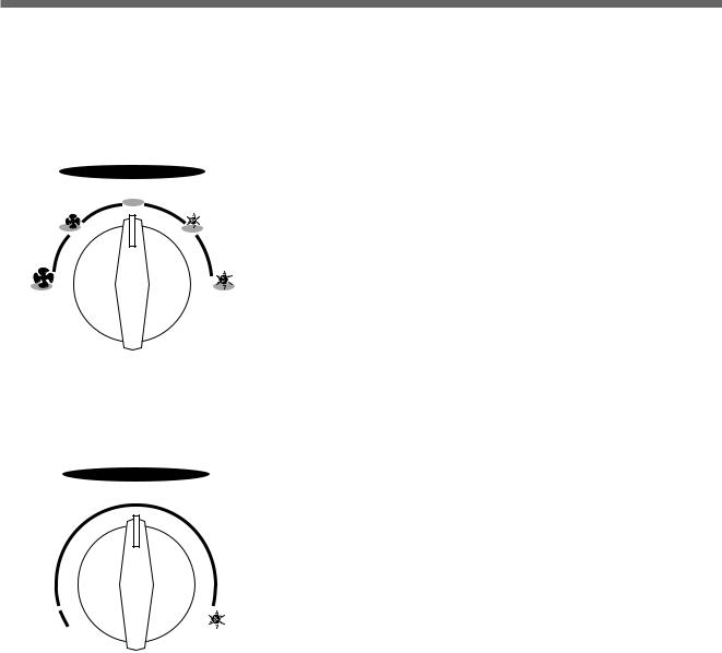
1. ROTARY SWITCH (SELECTOR)
Please refer to the part of selector in the chapter 9 (Wiring Diagram).
The rotary switch (selector) controls the fan motor’s rotation speed, and has five positions. The function of the five position is as follow.
|
SELECTOR |
|
OFF |
LOW |
LOW |
FAN |
COOL |
HIGH |
HIGH |
FAN |
COOL |
•OFF: This position stops all operations of the air conditioner.
•HIGH COOL: This position provides the maximum air flow for rapid
cooling, dehumidifying and dust removing operations. (Use this position on sultry summer days.)
• LOW COOL: This position provides the minimum air flow for quiet cooling, dehumidifying operations.
(Use this position on suitable for night-time.)
• HIGH FAN: This position provides the maximum air fiow alone fan operation without cooling operation.
• LOW FAN: This position provides the minimum air flow air flow alone fan operation without cooling operation.
2. THERMOSTAT (TEMPERATURE CONTROL)
• The Thermostat automatically starts and stops operation in order to keep THERMOSTAT the room temperature at a proper level, and this results in efficient use of
power and economical cooling.
• Turn clockwise for a cooler room temperature.
• Turn counter-clockwise for a warmer room temperature.
COOLER
3. MOTOR
The motor is used to rotate the indoor and outdoor fan so that the room air can be recirculated.
4.FAN
• BLOWER FAN: The Blower draws hot air from the room through the Evaporator and then discharges it back into the
cool air. It circulates the room air.
• PROPELLER FAN: The propeller draws outdoor air through louvering and cools Condenser, and then blows the hot air out.
5. CAPACITOR
The Capacitor enlarges the difference of phase between main coil and sub coil so that the Compressor and Fan Motor starts well.
6. ACCUMULATOR
The Accumulator blocks the unflow of liquid refrigerant and impurities into the Compressor.
5

5. GENERAL INFORMATIONS
1. CHANGING AIR FLOW DIRECTION
Air flow deflectors divert air from center flow to left or right. Adjust deflectors for desired air flow pattern.
2. AIR FLOW AROUND UNIT
Check in door grill and outdoor louvers for air flow obstructions. Do not block air flow to and from unit. The outdoor coil should be checked and periodically cleaned for debris that may collect and block unit air flow. If air flow is obstructed or deflected back into unit, the compressor may cycle on and off rapidly, causing early compressor failure.
3. Electrical Grounding Instructions.
This appliance is equipped with a three-prong(grounding) plug for protection against possible shock hazards. If a twoprong wall receptacle is encountered, the customer is required to contact a qualified electrician and have the twoprong wall receptacle replaced with a properly grounded three-prong wall receptacle in accordance with the National Electrical Code.
4. USE OF EXTENSION CORDS
Because of potential safety hazards under certain conditions we strongly recommend against the use of an extension cord. However, if you still elect to use an extension cord, it is absolutely necessary that it is earthed and the marked rating of the extension cord should be 250V 10A or more.
5. DRAIN HOLE AND WATER DRIPPING OUTSIDE
Locate drain hole at the rear of unit. Water in base pan is picked up by the fan blade and thrown onto the warm outdoor coil where it evaporates. The air conditioner must be installed level or tited or slightly to the outside for proper water disposal. On exceptionally hot and humid days the air conditioner may permit excess water to pass thru rear drain hole or overflow. This should be considered normal.
6

6. CARE AND MAINTENANCE
1. AIR FILTER
Clean the air filter, which removes dust inside the room.
It should be washed at least once every week during operation.
1.Remove the Air Filter from the front grill by pulling up.
2.Clean Air Filter with a vacuum cleaner or lukewarm, soapy water.
3.Shake it when clean to remove moisture completely. Replace it.
2.CLEANING THE AIR CONDITIONER
1.At least once a year, remove cabinet and thoroughly clean air conditioner. Have the unit inspected by an authorized servicer to ensure unit is functioning properly.
2.Wash air conditioner with lukewarm, soapy water as needed. Rinse and dry thoroughly.
3.If using concentrated liquid detergent, dilute in warm water first.
4.Front grill may be wiped off with a cloth dampened in a mild detergent solution.
5.Cabinet may be washed with mild soap or detergent and lukewarm water, then polished with liquid wax for appliances.
6.Condenser and Evaporator coils should be cleaned at the beginning of each cooling season. Use a soft brush or vacuum cleaner to clean them, making sure that the Condenser and Evaporator coils are not damaged.
7.Do not use abrasive cleaners. These items scratch, crack and discolor surfaces.
7

7. TROUBLE SHOOTING GUIDE
TROUBLE |
SITUATION |
|
ANALYSIS |
|
CAUSE |
REMEDY |
Fan motor and |
1. Power failure |
1) Power plug |
1) |
Power failure |
• Consult your electric company |
|
compressor do not |
|
|
|
|
|
|
run |
|
2) Circuit breaker |
2) |
Circuit breaker is tripped |
• In case of a breaker, turn it on |
|
|
|
|
|
|
|
and off a few times |
|
|
|
|
3) |
Power plug is not contacting |
|
|
|
|
|
|
|
• Replace the power plug |
|
|
|
|
|
||
|
2. Power is supplied, |
1) receptacle |
• Disconnection |
• Repair or replace the |
||
|
but the equipment |
|
|
|
|
receptacle |
|
does not run |
2) Operation switch |
• Mechanical failure of switch |
|
||
|
|
|
|
|
|
• Replace the cord or lead wire |
|
|
3) |
Cord or lead wire to |
1) |
Disconnection |
|
|
|
|
the switch |
|
|
|
|
|
|
|
2) |
Malfunction of contact |
|
|
|
|
|
|
||
Switch is in “cool” |
1. Not operating at all |
1) Compressor |
• Disconnection or burned-out |
• Replace the compressor or |
||
position but the |
|
|
|
|
|
connection wire |
compressor does not |
|
2) Thermostat |
1) |
Failure |
|
|
run |
|
|
|
|
|
• Replace |
|
|
|
|
2) |
Malfunction |
|
|
|
|
|
|
|
• Repair or replace |
|
|
|
|
3) |
Knob is not set to the proper |
|
|
|
|
|
|
setting |
• Turn knob for cooler setting |
|
|
3) |
Selector switch |
• Failure of malfunction of proper |
• Repair or replace the swtting |
|
|
|
|
|
setting |
|
|
|
|
|
|
|
|
• Repair |
|
|
4) |
O.L.P |
1) |
Disconnection |
|
|
|
|
|
|
|
• Repair or replace |
|
|
|
|
2) |
Malfunction of contact |
|
|
|
|
|
|
|
• Replace |
|
|
5) |
Capacitor |
• Lack of capacity |
|
|
|
|
|
|
• Disconnection |
• Repair |
|
|
|
|
|
|
|
|
|
2. Compressor |
1) Electricity |
1) |
The voltage exceeded allowed |
• Consult your electric company |
|
|
|
|
|
|
range |
|
|
|
|
|
|
|
• Check the capacity of wire |
|
|
|
|
2) |
Capacity of wire is not |
|
|
|
|
|
|
sufficient |
• Ventilate well and remove the |
|
|
|
|
|
|
heat source |
|
|
2) |
Room temperature |
• Extremely high |
|
|
|
|
|
and outside |
|
|
|
|
|
|
temperature |
• Burned-out |
• Replace |
|
|
|
3) |
Compressor |
• Malfunction |
• Replace |
|
|
|
4) |
O.L.P |
• Lack of capacity |
• Replace |
|
|
|
5) |
Capacitor |
|
|
|
|
|
|
|
|
||
|
3. Frequent start and |
1) Thermostat |
• Malfunction |
• Replace |
||
|
stop |
|
|
|
|
|
|
|
2) |
Capacitor |
• Lack of capacity |
• Replace |
|
|
|
3) |
O.L.P |
• Malfunction |
• Replace |
|
|
|
|
|
|
|
|
8
 Loading...