


S/M No:OSDV800001
Model : DV-800
Caution
:In this Manual, some parts can be changed for improving, their performance without notice in the parts list.
Dec . 2004

CONTENTS |
|
SPECIFICATIONS............................................................................................. |
2 |
ADVANTAGES OF THIS PRODUCT...................................................................... |
3 |
CIRCUIT OPERATIONAL DESCRIPTION................................................................ |
4 |
VOLTAGE CHARTS......................................................................................... |
16 |
CIRCUIT DIAGRAM........................................................................................ |
17 |
PCB CIRCUIT BOARD..................................................................................... |
27 |
INSTRUMENT DISASSEMBLY........................................................................... |
32 |
PARTSLIST.............................................................................................. |
36 |
! Caution :
In this Manual, some parts can be changed for improving.
1

SPECIFICATIONS |
 DVD Audio output standards
Output |
|
Disc type |
|
|
|
|
|
||
DVD |
VIDEO-CD |
CD |
||
|
||||
|
|
|
|
|
Analogue Audio output |
48/96KHz sampling |
44.1KHz sampling |
44.1KHz sampling |
|
|
|
|
|
|
Digital Audio output |
48KHz sampling |
44.1KHz sampling |
44.1KHz sampling |
|
|
|
|
|
2

ADVANTAGES OF THIS PRODUCT
·DVD,VCD,CD,CD-R,CD-RW,MP3,PIC-CD,CD+G playback function
·Integrated remote control
·Multiplex sound playback
·Progressive scan
·Mp3 file playback function
·GUI (Graphical User Interface) OSD (On Screen Display)
By using the [DISPLAY] button on the remote control, information on the DVD/VCD/CD player and disc, can be displayed on the TV screen.
·Screensaver function (DVD)
·3D sound (3D sound effect using 2 speakers)
·Coaxial digital output (PCM, Dolby Digital, DTS)
You can enjoy high-level digital audio by connecting with amp embedded with Dolby Digital / DTS decoder.
·Built-in Dolby Digital decoder
·Analog audio 2-channels output for DOWNMIX (x1)
·Composite video out (x1)
·Slow Forward / Reverse (DVD) playback
·Fast Forward / Reverse playback
·Search of title, chapter, and time in DVD disc, and search of track and time in VCD and CD
·Repeat playback (title and chapter for DVD, track and disc for VCD/CD)
·Repeat a defined period from A to B (DVD)
·Selective Play (DVD/VCD/CD)
You can select and play the desired title / chapter of DVD and track of Video CD
· Various languages OSD (On Screen Display) function (DVD)
You can select and display OSD among various languages. (English, French, Spanish)
· Parental Lock function (DVD)
This function can prevent playback of software that may be unsuitable for children.
· Multi Audio function (DVD)
The audio soundtrack can be heard in up to 8 languages. In the case of SVCD or VCD, it depends on the disc. (The number of audio languages depends on the software.)
· Multi Subtitle function (DVD)
The subtitle can be seen in up to 32 languages. In the case of SVCD or CVD, it depends on the disc. (The number of subtitle languages depends on the software.)
· Multi Angle function (DVD)
This function allows you to choose the viewing angle of scenes which were shot from a number of different angles. (The number of angles depends on the software.)
· Screen zoom function (DVD/VCD)
3

CIRCUIT OPERATIONAL DESCRIPTION
DVD Module
1.Summary
DVD One Board consists of: Loader part that reads and transmits audio and video data saved at Optic Discs (DVD, CD-DA, VCD, CD-R) to MPEG Decoder part; MPEG Decoder part, which, by decoding and encoding data received from the Loader, produces analog signals; and u-Com that controls the overall system including the loader and MPEG decoder.
2.How Does it Operate
Insert the power cord and then power transmitted to each IC, and the SET will be the STANDBY status which requires the least power for input the front panel key, input the STAND BY/ON key, extinguished the LED. Once the Power On key is entered, u- Com recognizes it and initiates each chipset, performs sequential algorithms such as determining whether the disc is in or not, and if in, what type of disc is loaded. Through this process, it can read disc data before transmitting it to the MPEG Decoder. The MPEG Decoder will then decode and encode such data before generating the final analog audio and video signal outputs.
4

CIRCUIT OPERATIONAL DESCRIPTION
3.Loader Part
The loader which read the data of audio/video from optic disc and transfer them to MPEG decoder can be divided into Deck total DVD assay(in a short term, Mecha) and Servo. Mecha mounts with the optical pick-up which allows reading the signal of a disc using laser beam and makes it operates and consists of the deck mechanism which allows loading a disc and reading the data. Servo is a sort of circuit which allows operating the loader and recovering the data and consists of Motor Drive IC operating the spindle, the sled, the loading motor.
5
CIRCUIT OPERATIONAL DESCRIPTION
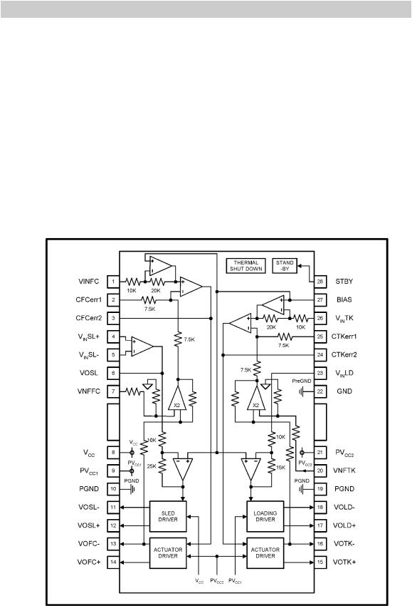
1) Motor Drive IC: AT5654
The AT5654 is a 4-channel BTL driver IC for driving the motors and actuators in products such as CD-ROM/DVD-ROM/DVD-Player drives. Two of the channels use current feedback to minimize the current phase shift caused by the influence of load inductance.
Driver IC generates the focus signal and the tracking signal for pick-up actuator, the sled signal for feed, spindle signal and the load signal for opening and closing of the tray. The focus signal, the tracking signal, the sled signal and the spindle signal are input into each relaxant port of the drive IC(in the order of No. 26 pin, 23, 4, and 1) and set the gain amplification and the center voltage through the internal OP-AMP and drive on both sides and then the focus signal and the tracking signal will be output as VOFC+, VOFCand VOTK+, VOTKon actuator, the sled signal and the spindle signal will be output as VOSL+, VOSLand VOLD+, VOLDon each motor. For the load signal the input opening/closing signal is output as VOTR+, VOTRthrough the loading PRE FWD REV circuit.
Motor Drive IC (AT5654) Block Diagram
6

CIRCUIT OPERATIONAL DESCRIPTION
MPEG Decoder
The signal read from DVD disc is output into the RF signal and Servo related signal through the RF IC and they are input into the MPEG decoder and processed the MPEG decoding and divided into video/audio signal. The video signal is output into the analog audio signal through the built-in encoder block and also the audio signal into the audio DAC through the audio decoder block.
MPEG decoder consists of existing MPEG-2 decoder and single chip combined the digital signal processing part which is the core technology of DVD player with the Servo controller.
1)DVD Servo And MPEG-2 Decoder : MT1379
Servo Controller
The servo control is accomplished through the servo DSP (Servo Digital Signal Processor) and its accessory I/O circuits. This servo DSP is capable of performing complex operations and also provides a friendly interface for the system controller. By issuing type 1 and type 2 commands from the system controller, the servo DSP can accomplish various complicated servo control functions, such as tracking, seeking and MT1336/MT1376 chip register programming. As for the servo I/O circuits, it provides interface between the input servo signals and the Servo DSP. It has built-in ADCs to digitize the servo control signal and DACs to provide signals for the actuator and sledge motor. It also has a serial interface to communicate with the MT1336/MT1376 chip.
Analog Front End
The analog front end contains a data slicer circuit and a data PLL circuit. The RF analog signal from MT1336/MT1376 is quantized by the data slicer to form the EFM/EFM+ bit stream, from which the channel bit clock is extracted by the data PLL. The EFM/EFM+bit stream and bit clock are then output to DPU for channel bit processing.
DPU
Data path unit (DPU) provides protection on data with lost synchronization patterns and demodulates EFM/EFM+ bit stream into the channel raw data that will be corrected by the decoder. The synchronization protection makes data after the synchronization pattern to be extracted even if the synchronization pattern is not found.
Spindle Controller
The spindle controller is used to control disc spindle motor. It includes a varipitch CLV clock generator, a CLV/CAV controller, and a PWM generator. The varipitch CLV clock enerator generates a reference clock for the speed of operation. The CLV/CAV controller changes the mode and speed of operation according to servo register setting. The PWM generator generates pulse-width-modulated signal to drive disc spindle motor driver.
CSS/CPPM
The CSS/CPPM module provides functions necessary for decoding discs conforming to CSS/CPPM specification.
7

CIRCUIT OPERATIONAL DESCRIPTION
System Parser
The system parser is used to help the system controller to decode DVD/SVCD/VCD bit stream just after the channel decoder performing error correction. Acting as a DMA master, it moves bit stream data from RSPC buffer to video, audio, or sub-picture buffer according to system controller request. It also decrypts the scramble data of the CSS/CPPM sectors. Another function of system parser is providing system controller/DSP a DRAM memory copy controller to enhance system controller/DSP performance.
Video Decoder
The primary function of MT1379 is to support MPEG1 and MPEG2 video decoding. The video decode engine comprises of variable length decoder (VLD), inverse transformer (IT), motion compensator (MC), and block reconstructor (BR). The video decode engine decodes the variable length encoded symbols in MPEG bit stream and performs inverse scan, inverse quantization, mismatch control and inverse discrete cosine transform onto the variable length decoded data. The motion compensator fetches prediction data from reference picture buffer according to motion vectors and motion prediction mode for P and B pictures. Finally, the block reconstructor combines both the results of inverse transformer and motion compensator to derive the reconstructed image macroblock and write back to picture buffer. The video decode engine can also support JPEG and BMP file decoding by common image compression hardware kernels.
Video Output
The Video Output unit contains Video Processor, SPU, OSD, Cursor, TV encoder units, it performs
·Reading decoded video from DRAM buffer
·Scaling the image
·Gamma/Brightness/Hue/Saturation adjustment and edge enhancement
·Reading and decoding SPU and OSD data from DRAM buffer
·Generating hardware cursor image
·Merging the video data, SPU, OSD and cursor
Video Processor
The Video Processor unit controls the transfer of video data stored in the DRAM to an internal or external TV encoder. It uses FIFOs to buffer outgoing luminance and chrominance data, and performs YUV420 to Y U V 4 2 2 c o n v e r s i o n a n d a r b i t r a r y v e r t i c a l / h o r i z o n t a l decimation/interpolation, from 1/4x to 256x. With this arbitrary ratio scaling capability, the Video Processor can perform arbitrary image conversion, such as PAL to NTSC, NTSC to PAL, MPEG1 to MPEG2, Letterbox, Pan-Scan conversion or zoom in, zoom out. It is also capable of interlace to progressive conversion.
The Video Processor unit performs the following functions:
· Requests and receives the decoded picture data from the picture buffer in
external DRAM for display
8

CIRCUIT OPERATIONAL DESCRIPTION
·Resample vertical data to create 4:2:2 sample format
·Optionally performs vertical/horizontal resampling of both luminance and chrominance data
·Performs optional Gamma correction, luminance/chrominance adjustment, and edge enhancement
The Video Processor unit contains two 2-tap vertical filters for luminance and chrominance. These filters are used to interpolate and reposition luminance and chrominance line to improve picture quality. These filters are capable of generating up to eight, unique subline value between two consecutive scan lines. The generation of lines depends on the ratio between the height of the source image and the target image. In applications where DRAM bandwidth are critical the filters can be configured as simple line-repeating to reduce the DRAM bandwidth required.
The Video Processor unit integrates two separate horizontal postprocessing filter, a simple 2-tap linear horizontal filter and an 8-tap programmable filter. These filters are provided for scaling images horizontally along the scan line. These two filters is capable of generating up to eight, unique subpixel values between two consecutive pixels on a scan line. The generation of pixels depends on the ratio between the width of the source image and the target image.
SPU
This is a hardware sub-picture decoder. It decodes the compressed SPU image bitstream and CHG_COLCON commands according to SPU header information previously decoded by system controller. The SPU module also allows two SPU objects to be displayed at the same time. SPU image is blended with main video stream.
OSD
The OSD module can operate with 2/4/16/256-color bitmap format (1/2/4/8 bits), and 16/256 color RLC format, all have 16 levels of transparency. In addition, it accepts an special WARP mode, which inserts one programmable RLC code in the bitmap to reduce the image size stored in DRAM. It also features automatic shadow/outline generation in 2-color mode, 2 Hilight areas, 1 Change Color area and 1 OSD Void area. One OSD area can occupy the full or a partial screen, or multiple OSDs can occur in a screen at the same time, only if they don't occupy the same horizontal line. The output image is blended with the video-SPU mixed stream.
Cursor
A hardware cursor generator is integrated in Video Output Unit. The cursor image is a 32x32 4-color bitmap image, each colors are programmable. Cursor can be enlarged by 2 in both vertical and horizontal directions. Cursor image is multiplexed with video-SPU-OSD mixed stream.
9
CIRCUIT OPERATIONAL DESCRIPTION
Audio Interface
Audio interface consists of Audio Output Interface and Microphone Input Interface.
Audio Output Interface
The MT1379 can support up to 8 channel audio outputs. The output formats can be 16, 24, or 32-bit frames. Left alignment, right alignment, or I2S formats are all supported.
With built-in PLL, MT1379 can provide the audio clock (ACLK) for external audio DAC at 384Fs, where Fs is usually 32KHz, 44.1KHz, 48KHz, 96KHz, or 192KHz. ACLK can also be programmed to be from outside MT1379. When ACLK is input to MT1379, the frequency could be 128*n Fs, where n is from 1 to 7.
Audio raw (encoded) data or cooked (decoded) data can be output on a single line using S/PDIF interface. The output slew rate and driving force of this pad are programmable.
Microphone Input Interface
The MT1379 provides a microphone input interface. Two independent microphones' data could be input to the MT1379. There are two independent digital volume control for these two input channels. The input data formats can also be left alignment, right alignment, or I2S formats.
System Controller
MT1379 uses an embedded Turbo-8032 as System Controller and provide ICE interface to increase the feasibility of F/W development. Also, MT1379 includes an build-in internal 373 to latch lower byte address from 8032 Port 0 and provide a glue-logic free solution. MT1379 supports up to 1M X 16 bits Flash ROM to store 8032 code, H/W related data, User data, etc. F/W upgrade can be achieved either by debug interface or by disk.
10 |

CIRCUIT OPERATIONAL DESCRIPTION
2) DVD Servo RF IC : MT1336
MT1336 is a high performance CMOS analog front-end IC for both CD_ROM driver up to 48XS and DVD-ROM driver up to 16XS. It also supports DVD-RAM read up to 4XS Version 2. It contains servo amplifiers to generate focusing error, 3-beam tracking error, 1 beam radial push-pull signal, RF level and SBAD for servo functions. It also includes DPD tracking error signal for DVD_ROM application. For DVD-RAM disks, there are also Differential Push-Pull (DPP) method for generating tracking signal and Differential Astigmatic Detection (DAD) for processing focusing signal. Programmable equalizer and AGC circuits are also incorporated in this chip to optimize read channel performance. In addition, this chip has dual automatic laser power control circuits for DVD-ROM (DVD-RAM) and CD-ROM seperately and reference voltage generators to reduce external components. Programmable functions are implemented by the access of internal register through bi-directional serial port to configure modes selection.
11 |

CIRCUIT OPERATIONAL DESCRIPTION
3) Flash Memory : AT49F8192AT(HY29F800ABT-70,A29800UV-70,A2980TV-70)
This stores every program required for the operation of DVD player and holds the data of OSD languages and LOGO and send them upon request from u-COM. This allows the update of firmware by CD-R/RW. For DVD module, 8MBit Flash Memory on 512K x 16bit basis is used.
Description
The AT49F8192A(T) are 5-volt, 8-megabit Flash memories organized as 1,048,576 words of 8 bits each or 512K words of 16 bits each. Manufactured with Atmel's advanced nonvolatile CMOS technology, the devices offer access times to 90 ns with power dissipation of just 275 mW. When deselected, the CMOS standby current is less than 100 µA.
The device contains a user-enabled “boot block” protection feature. Two versions of the feature are available: the AT49F8192A(T) locates the boot block at lowest order addresses (“bottom boot”); the AT49F8192A(T) locates it at highest order addresses (“top boot”).
To allow for simple in-system reprogrammability, the AT49F8192A(T) does not require high-input voltages for programming. Reading data out of the device is similar to reading from an EPROM; it has standard CE, OE and WE inputs to avoid bus contention. Reprogramming the AT49F8192A(T) is performed by first erasing a block of data and then programming on a byte-by-byte or word-by-word basis.
12
CIRCUIT OPERATIONAL DESCRIPTION
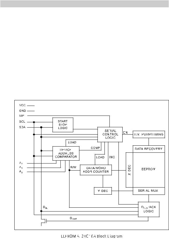
4) EEPROM : AT24C16A
This stores the information related to setup of DVD menus. This can read and write the optional information such as OSD, voice, language option after function for subtitle etc, the aspect or method of TV display, video option like display function and audio, screen saver, parental function through the I2C transmission method.
Description
The AT24C16A provides 16384 bits of serial electrically erasable and programmable read only memory (EEPROM) organized as 2048 words of 8 bits each. The device is optimized for use in many industrial and commercial applications where low power and low voltage operation are essential. The AT24C16A is available in space saving 8-lead PDIP, 8-lead JEDEC SOIC, 8-lead MAP and 8-lead TSSOP packages and is accessed via a 2-wire serial interface. In addition, the entire family is available in 2.7V (2.7V to 5.5V) and 1.8V (1.8V to 5.5V) versions.
13

CIRCUIT OPERATIONAL DESCRIPTION
5) SDROM : AE39S2016-7(AW39S2016-7,L43L16032ATF-7O,PT480416TG-7O)
This sends and receives data with MPEG decoder and performs the video signal processing. Every video signal output from DVD player is once stored in SDRAM and then encoded in MPEG decoder and finally output into the analog signal.
SDRAM applied to DVD module has the capacity of 32MBit(1048576 x 16bit x 2Bank), sends and receives data with MPEG decoder by 16 bit.
Description
The AE39S2016-7 organized as 2-bank x 1048576-word x 16-bit (2M X 16), fabricated with high performance CMOS technology. Synchronous design allows precise cycle. Range of operating frequencies, programmable burst length and programmable latencies allow the same device to be useful for a variety of high bandwidth, high performance memory system applications.
14
 Loading...