


DV6T811N-LT

S/M No. : VTB811NET0
Service Manual
T
DAEWOO ELECTRONICS CO., LTD.
Jun. 2002
http : //svc.dwe.co.kr
VC
R
DV
D
RE
PE
A
T
OP
EN
/
CL
OS
E
DI
SP
L
A
Y
TI
TL
E
/P
BC
ME
NU
PR
P
R
OU
TP
U
T
PR
EV
RE
C
PR
OG
R
AM
CL
K/
C
NT
SP
E
E
D/
A
N
GL
E
TR
AC
K
IN
G
TV
/V
C
R
MA
RK
SE
AR
C
H
S
YS
TE
M
PL
A
Y/
P
AU
SE
NE
XT
Z
OO
M
AU
DI
O
SU
BT
I
TL
E
R
E
T
U
R
N
/
O
K
CLEAR/3D
S
E
T
U
P
E
N
T
E
R
MODEL : DV6T811N-LT
DV6T813N-QJ
DV6T821N-QJ/X
DV6T813N-QJ/X
DV6T823N-QJ/M

1
SPECIFICATIONS..................................................................................................................2
ADVANTAGES OF THIS PRODUCT ......................................................................................3
TROUBLE SHOOTING .......................................................................................................................5
WAVEFORMS ...................................................................................................................................25
CIRCUIT DIAGRAM .........................................................................................................................28
PCB CIRCUIT BOARD.....................................................................................................................39
INSTRUMENT DISASSEMBLY......................................................................................................44
ELECTRICAL PARTSLIST................................................................................................................49
CONTENTS
1.
2.
3.
4.
5.
6.
7.
8.
2
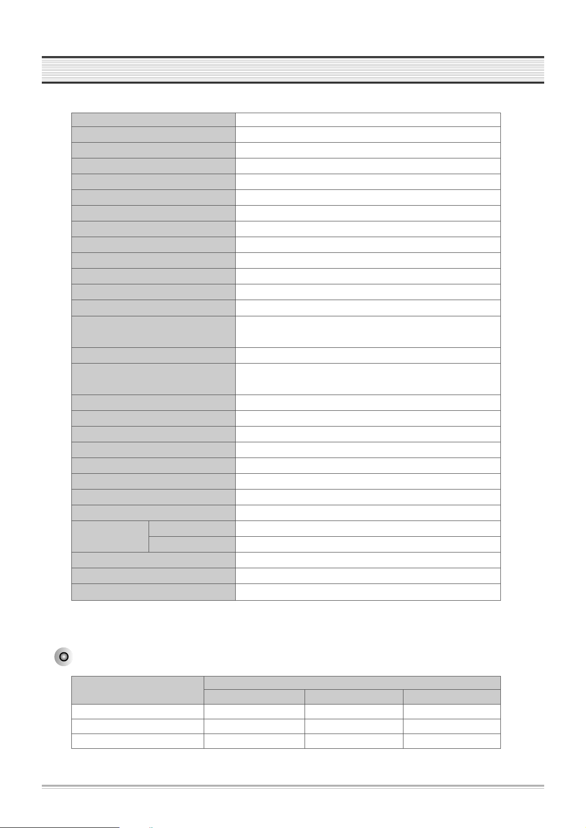
SPECIFICATIONS
DVD Audio output standards
Power AC 120V, 60Hz
Consumed electricity 24W (supplementary 2.5W)
W eight 5.7kg
Dimension (WxHxD) 430mmx91mmx355.5mm
Operative temperature +5°C~35°C
Installation condition Horizontal / Relative humidity under 80%
Received channels VHF: 2-13 CH / UHF: 14-69 CH / Cable: 1-125
Signal type NTSC COLOR
Antenna Input/output U/V-mixed: 75Ωunbalanced
VIDEO input 1.0 Vp-p unbalanced, RCA JACK
AUDIO input -8.8dBm, RCA JACK
VHF output 3 or 4 CH
VIDEO output (
common use of DVD and VCR
) VIDEO output terminal, 1.0 Vp-p unbalanced, RCA JACK
VIDEO output (DVD only) S-VIDEO output (75Ω In load Y : 1.0Vp-p, C:0.286Vp-p)
COMPONENT output (75ΩIn load Y: 1.0Vp-p, Pb:0.7Vp-p, Pr:0.7Vp-p)
AUDIO output (
common use of DVD and VCR)Audio output terminal (2 kinds): -8.8dBm(VCR), 2.0Vrms(DVD), RCA JACK
AUDIO output (DVD only) Analogue AUDIO output (2 CH): 2.0V rms
Digital audio output (OPTICAL, COAXIAL)
Playable tape Very high dense tapes with VHS marks
Playable disc DVD, VIDEO-CD, CD (12mm), CD (8mm), MP3, CD-R, CD-RW
T ape speed Standard: 33.35mm/s, 3 times: 11.12mm/s
Playtime Standard: 2hrs, 3 times: 6hrs (use of T120tape)
Clock display 12 hrs AM/PM
Time Recording 8 programs a year
Persistence in power failure 1min
VIDEO S/N (VCR) Over 45dB(Standard recording)
Resolution VCR Over 220 lines (Standard recording)
DVD Over 500 lines (DVD Disc PLAY)
AUDIO (VCR) Over 69dB(Hi-Fi), over 40dB(Mono)
AUDIO (DVD) 90dB
AUDIO dynamic range 90dB
Disc type
DVD VIDEO-CD CD
Analogue Audio output 48/96KHz sampling 44.1KHz sampling 44.1KHz sampling
Digital Audio output 48KHz sampling 44.1KHz sampling 44.1KHz sampling
Optical digital audio output 48KHz sampling 44.1KHz sampling 44.1KHz sampling
Output
1.

ADVANTAGES OF THIS PRODUCT
3
* DVD, VCD, CD, CD-R(MP3), CD-RW, VHS, S-VHS playback function
* DVD one-touch record function
* Watching DVD for recording broadcast
* Integrated REMOTE (VCR, DVD)
* Ultra power savings : less than 3W for stand-by mode
* VISS function
* Multiplex sound playback/record
* High Sound Quality of 6 head Hi-Fi
* One Touch timer Recording (OTR
)
* MP3 file playback function (CD-R disc having records of MP3 files
)
* Various video type-supported (AUTO, NTSC and PAL)
* GUI (Graphical User Interface) OSD (On Screen Display)
By using the [DISPLAY] button on the remote control, information on the DVD/VCD/CD player and disc, can be displayed on the TV
screen.
* Screensaver function (DVD)
* 3D sound (3D sound effect using 2 speakers)
* High bit / high sampling with 27MHz / 10bit video encoder
This unit has 27MHz / 10bit capability, that enables the faithful reproduction of fine images.
* High bit / high sampling with 96KHz / 24bit audio D/A converter
With this 96KHz / 24bit linear Pulse Code Modulated signals, which constitute the highest specifications in the DVD standards, you
can enjoy faithfully reproduced sound in all of its various modes. To support 96KHz sampling / 24bit sound, the shaping noise of this
multi-level digital sigma type of D/A converter is kept flat up to 44KHz, thus preventing the important audio signals from being
affected.
* Coaxial, Optical digital output (PCM, Dolby Digital, dts
)
You can enjoy high-level digital audio by connecting with amp embedded with Dolby Digital / dts decoder.
* Built-in Dolby Digital decoder (DVD)
* Analog audio 2-channels output for DOWNMIX (x1
)
* Composite video out (x1)
* S-Video out (x1)
2.

4
ADVANTAGES OF THIS PRODUCT
* Slow Forward / reverse (DVD) playback
* Fast Forward / reverse playback
* Search of title, chapter, and time in DVD disc, and search of track and time in VCD and CD
* Various TV aspect (DVD)
4:3 for Pan and Scan, 4:3 for Letter Box, and 16:9 for Wide
* Repeat playback (title and chapter for DVD, track and disc for VCD/CD)
* Bookmark function (DVD)
Playback position can be made to remember up to 3 positions for speedy search.
* Selective Play (DVD/VCD/CD)
You can select and play the desired title / chapter of DVD and track of Video CD/CD in STOP mode.
* 3 languages OSD (On Screen Display) function (DVD)
You can select and display OSD in 3 languages. (English, French, Spanish)
* Parental Lock function (DVD)
This function can prevent playback of software that may be unsuitable for children.
* Multi Audio function (DVD)
The audio soundtrack can be heard in up to 8 languages. In the case of SVCD or CVD, it depends on the disc. (The number of audio
languages depends on the software.)
* Multi Subtitle function (DVD)
The subtitle can be seen in up to 32 languages. In the case of SVCD or CVD, it depends on the disc. (The number of subtitle languages
depends on the software.)
* Multi Angle function (DVD)
This function allows you to choose the viewing angle of scenes which were shot from a number of different angles. (The number of
angles depends on the software.)
* Screen zoom function (DVD/VCD)
* Thumbnail view function (in VCD with inactivated PBC)
5
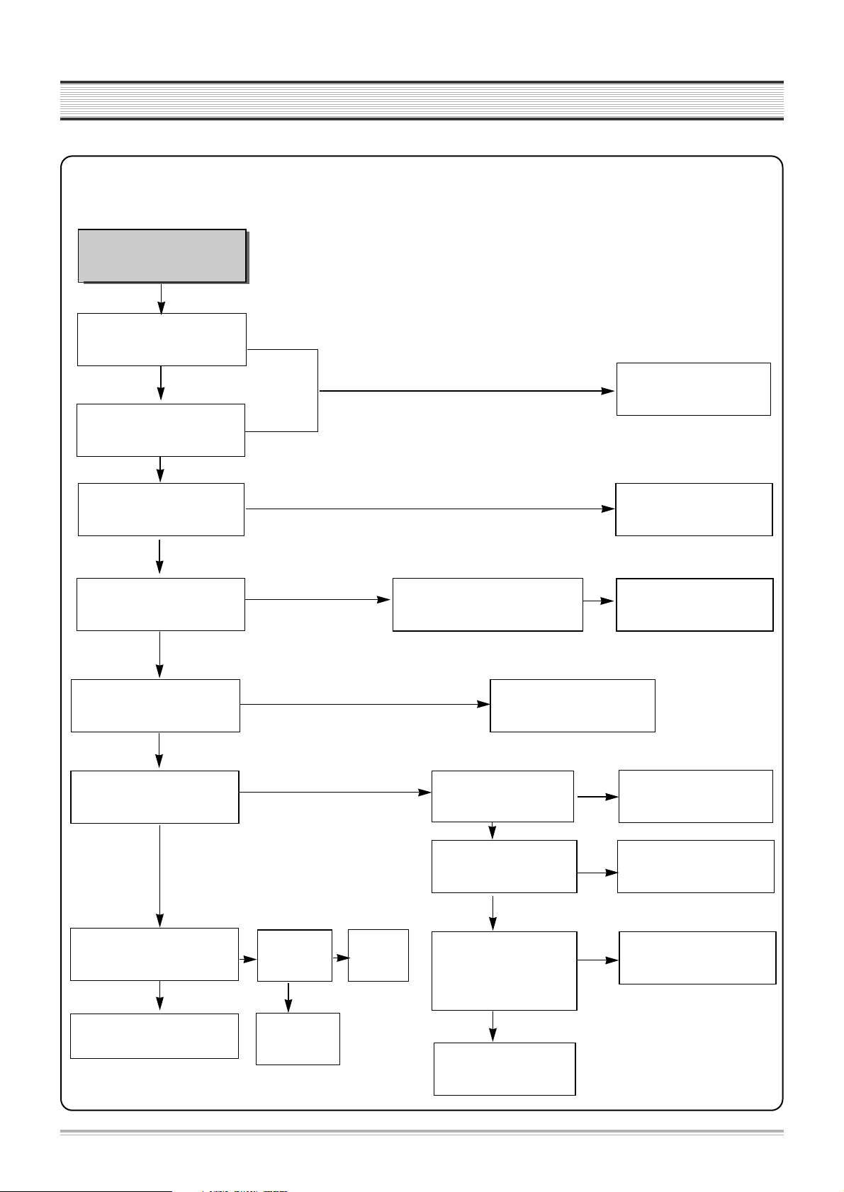
TROUBLESHOOTING
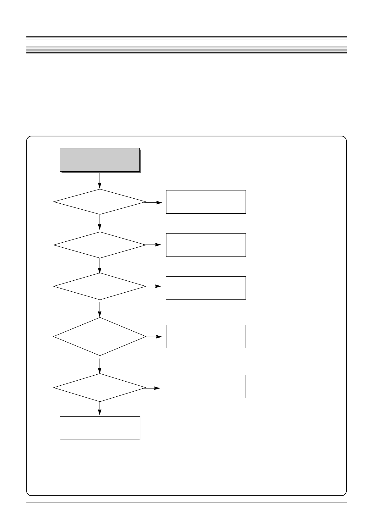
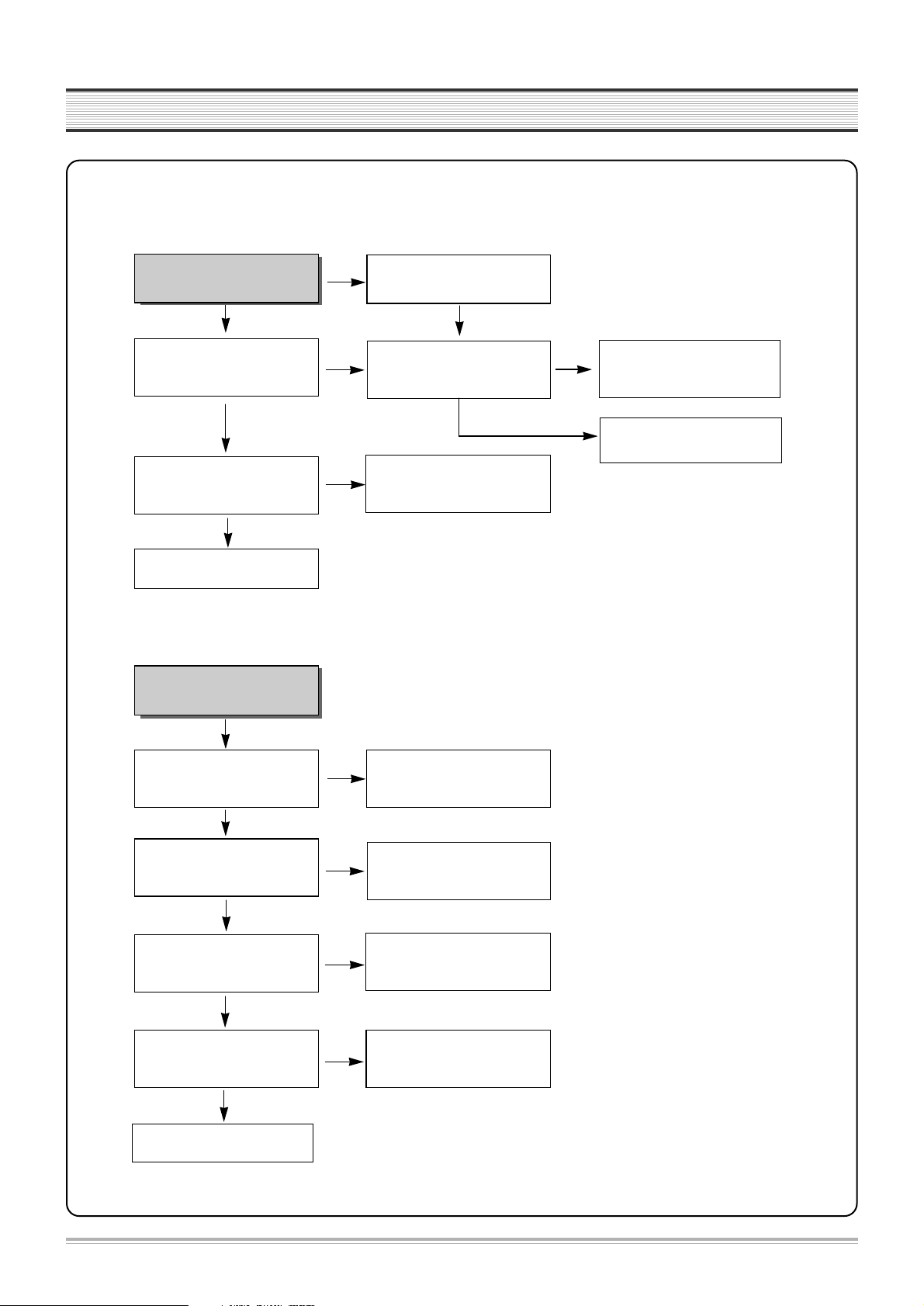
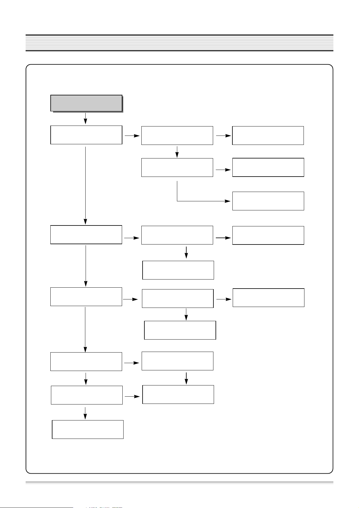
1. POWER CIRCUIT
✓ CAUTION
You must use insulated trance during the first part test of POWER circuit.
Check IC601,IC701.
No power
POWER cord is ok?
Is 400~140V voltage
obtained at C805 +?
Output voltage of 2
nd
parts is normal?
Check
rectifier diode of 2
nd
parts ;
D821, D822, D823, D825,
D826, D827, D828.
Switching
pulse of IC801 pin#4 or
pin#5 is normal?
OK
Exchange POWER CORD
Check
G801,L801,L802,D801.
Exchange rectifier diode of
2ndparts ; D821, D822, D823,
D825, D826, D827, D828.
Check IC801.
NO
YES
YES
YES
YES
YES
NO
NO
NO
NO
3.
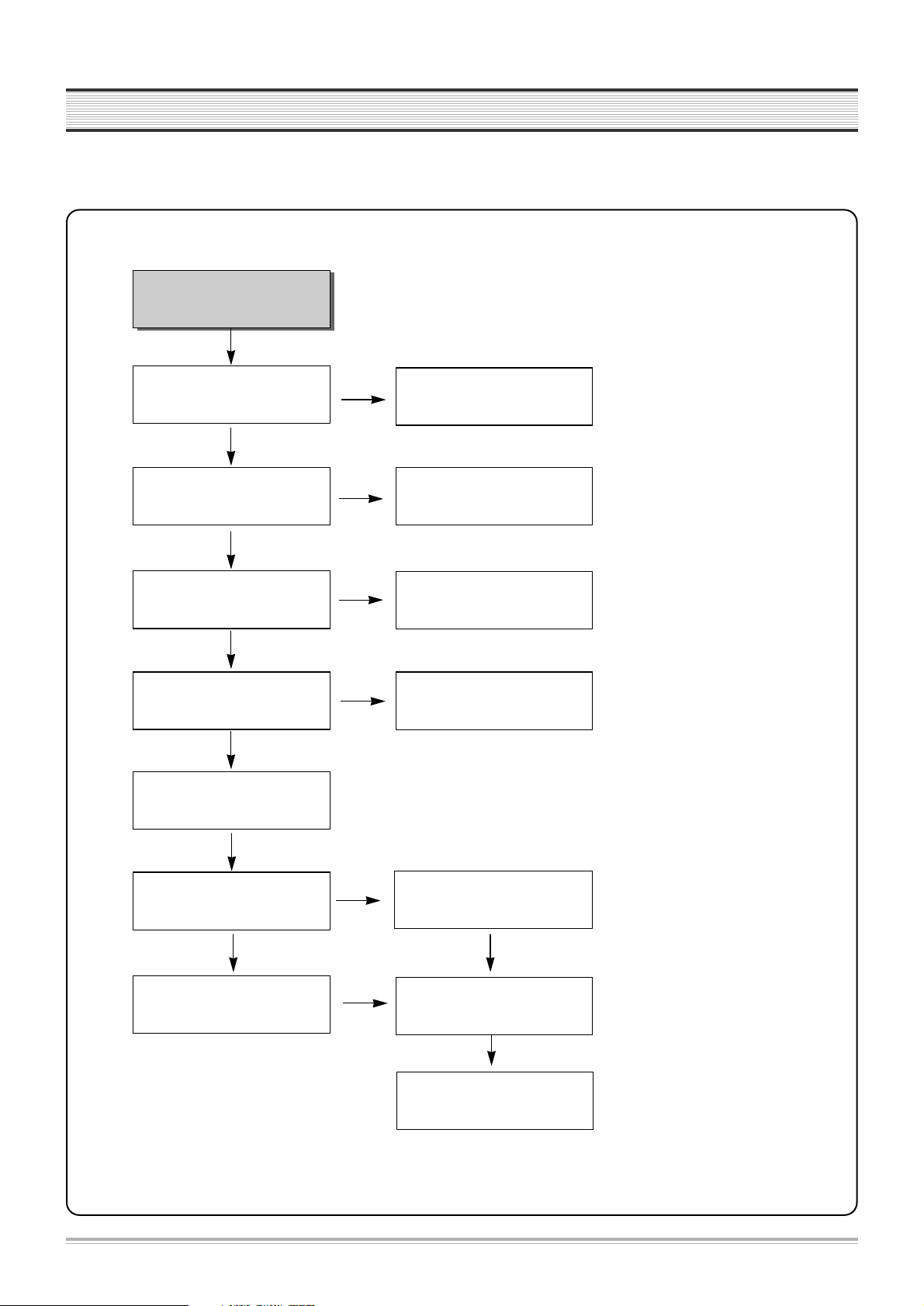
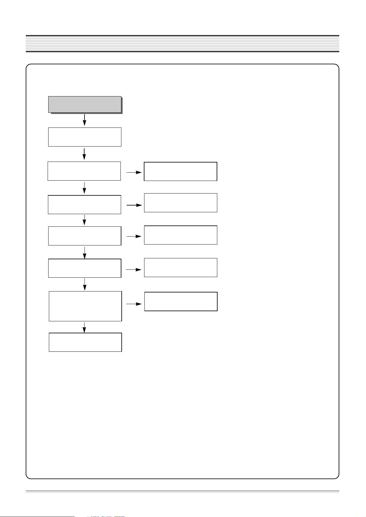
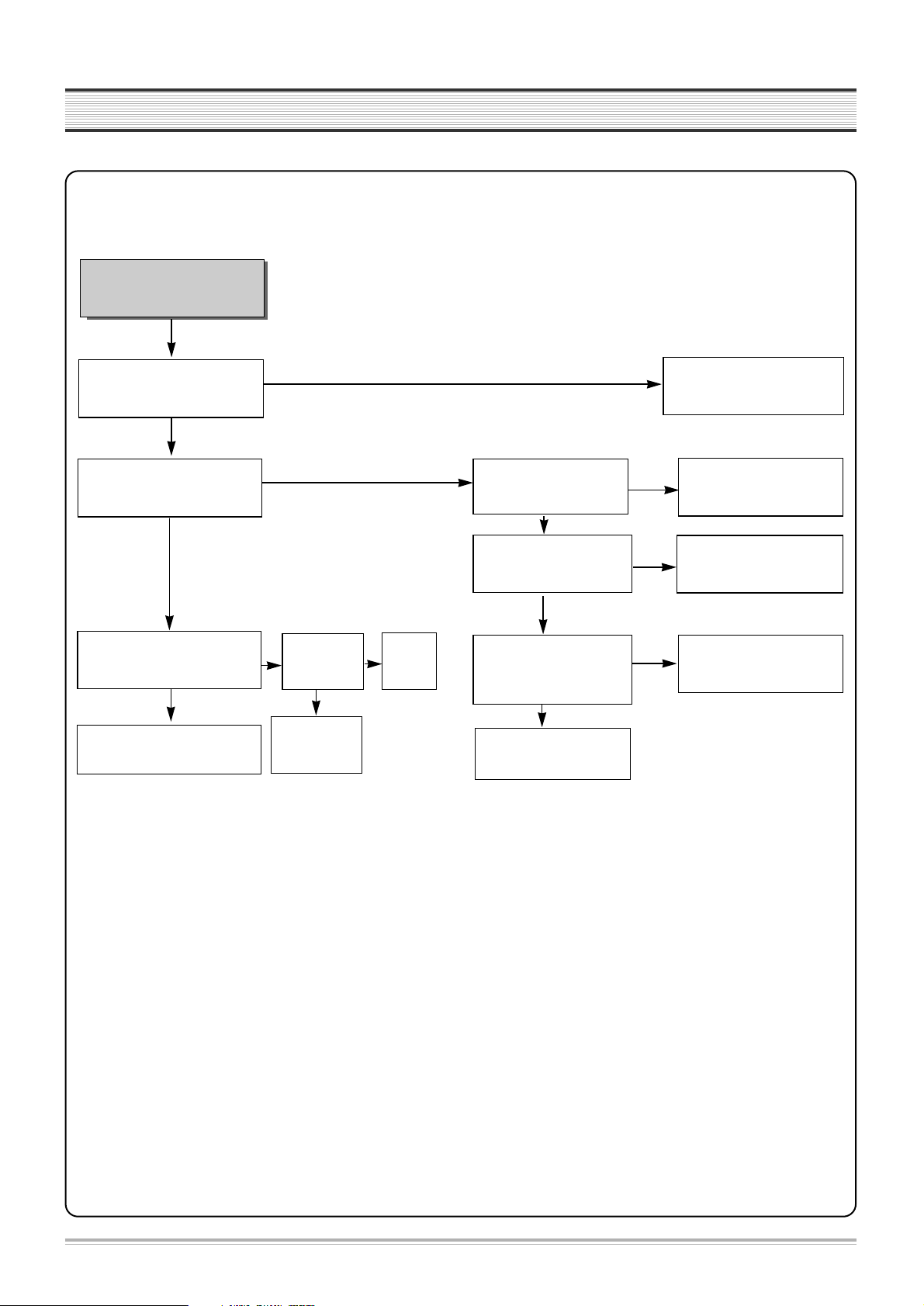
2. SYSTEM CIRCUIT
6
TROUBLESHOOTING
No VFD display.
Is 5V obtained at IC701 pin#1?
Is -26V obtained at IC701
pin#16~17?
Oscillation at IC701 pin #2?
Is -22V, -18V obtained at F
F+?
Specific GRID/SEG doesn’t
function.
Check D701.
Check POWER circuit at -26V.
Check C704, IC701.
Check IC 701 pin #18~27.
Check IC 701 pin #28~43.
NO
YES
YES
YES
YES
NO
NO
NO
NO
GRID output at PORT of
IC701?
YES
SEG output at PORT of IC701?
Check POWER circuit at F-, F+.
Exchange IC601.
YES
A. VFD DISPLAY
NO
7
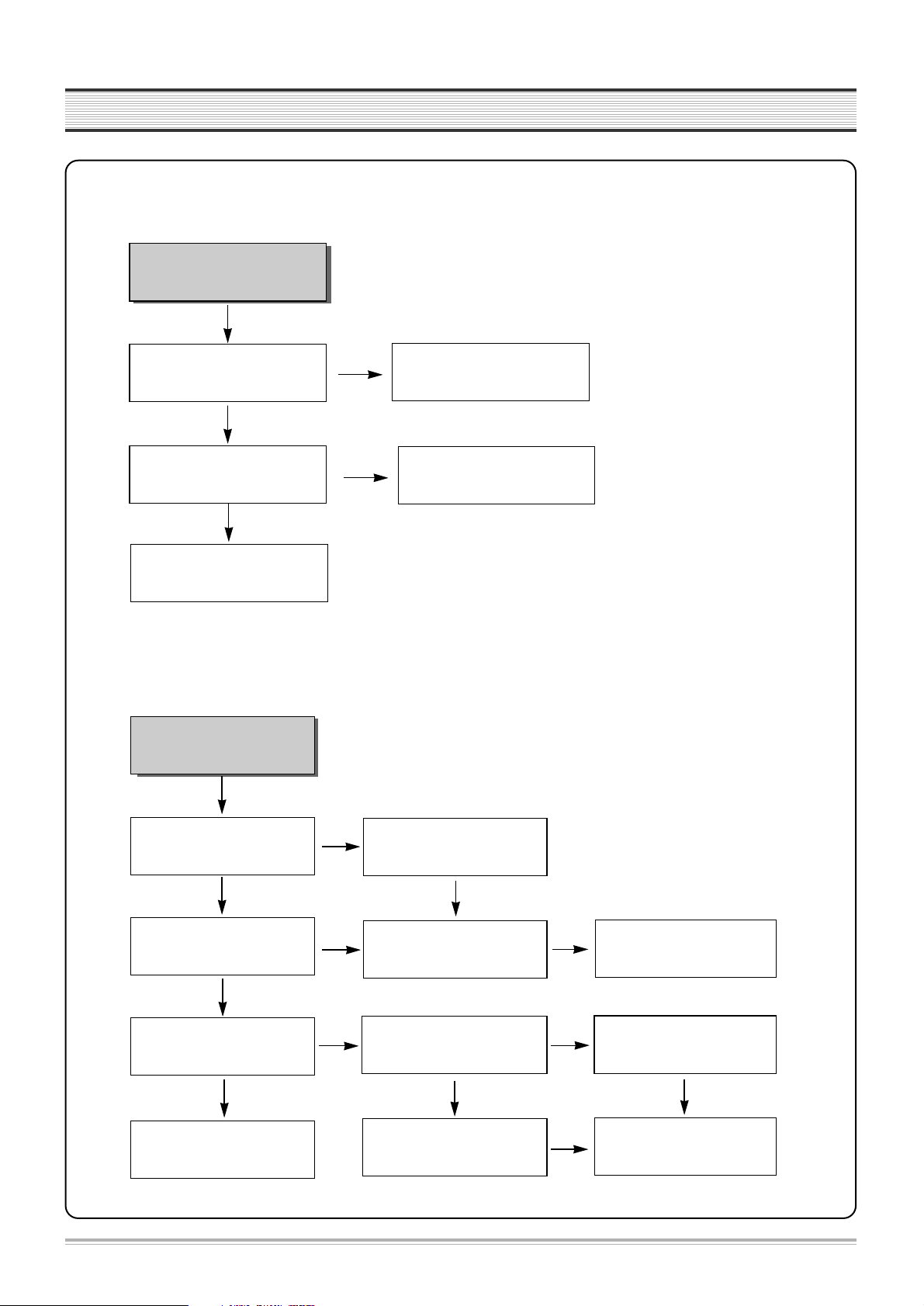
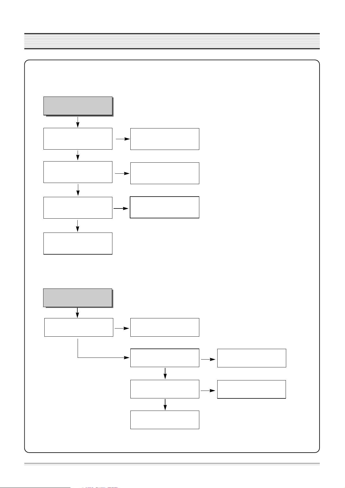
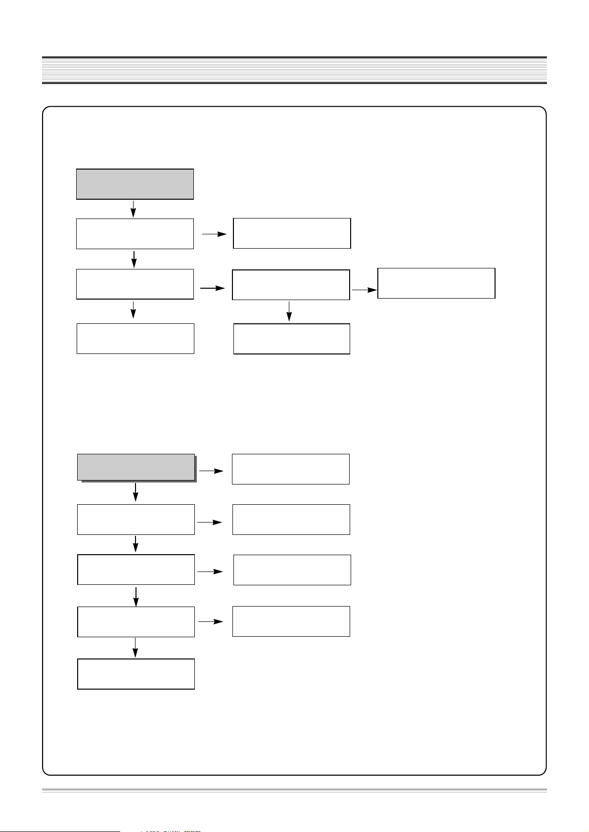
TROUBLESHOOTING
No power compensation.
Voltage of power fail (IC601
pin#100) at micom is 0.7V over?
More than 3.2V is maintained
for 1 minutes at IC601 pin#37
during Power Cord Open.
Check R625.
NO
YES
B. No power compensation.
YES
Check RESET circuit.
NO
Exchange IC601.
Noise appears on the
playback screen.
Is noise diminished by tracking
adjustment.
Noise band is trembled up and
down?
Re-adjust PATH.
Is the height of CTL HEAD normal?
No dust?
Is there problem in CTL Input
circuit and amplifier.
YES
NO
NO
NO
Is there CTL pulse at IC601
pin#97?
Check IC601.
Noise appears on the screen
even though changing tape.
Re-adjust the height of AC
HEAD. Remove the dust.
Check C651, C652, R651~R653
IC601 pin #91, 92, 98.
NO
Re-adjust PATH.
C-1. Bad playback quality (1)
YES
YES
YES
YES
8
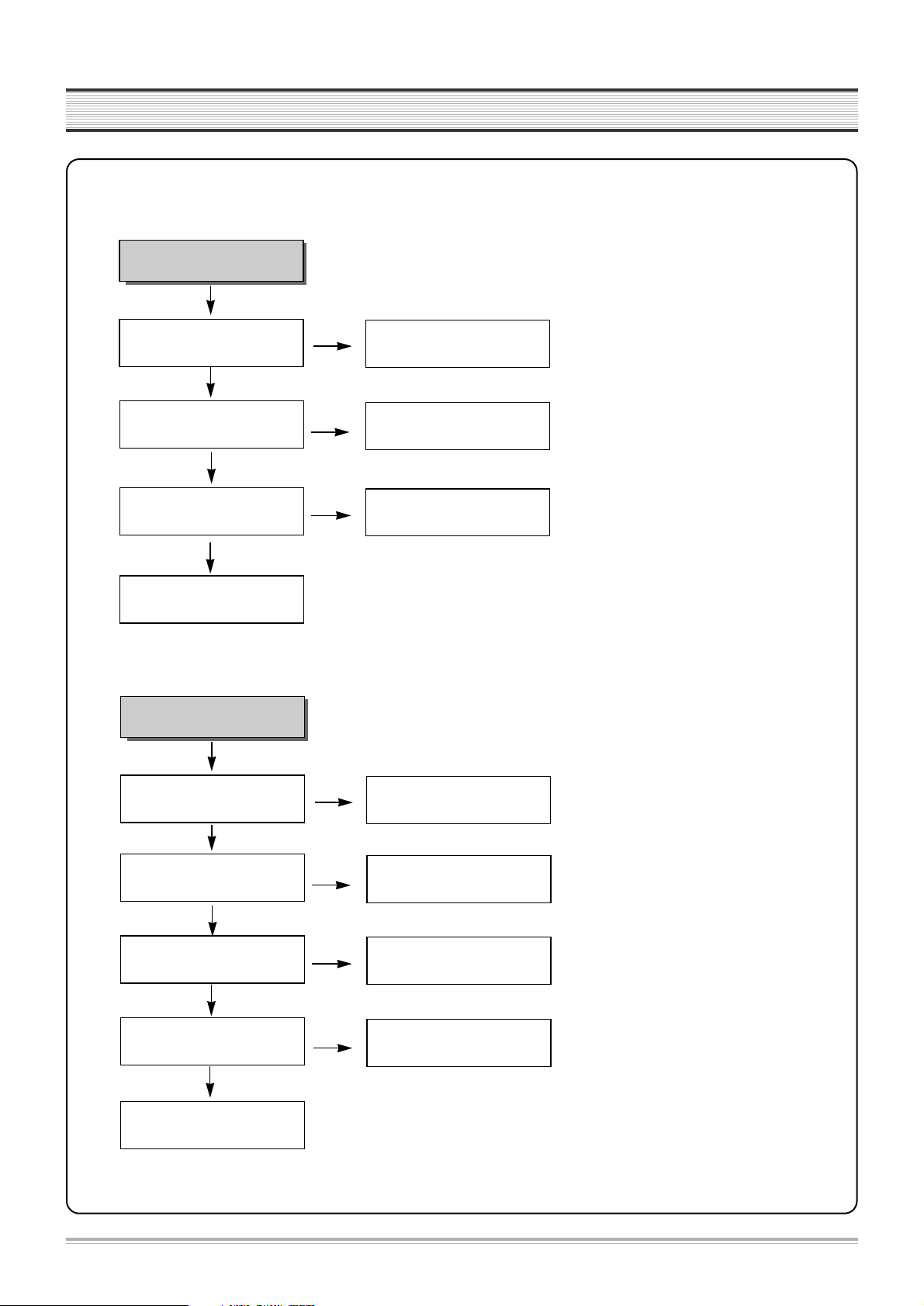
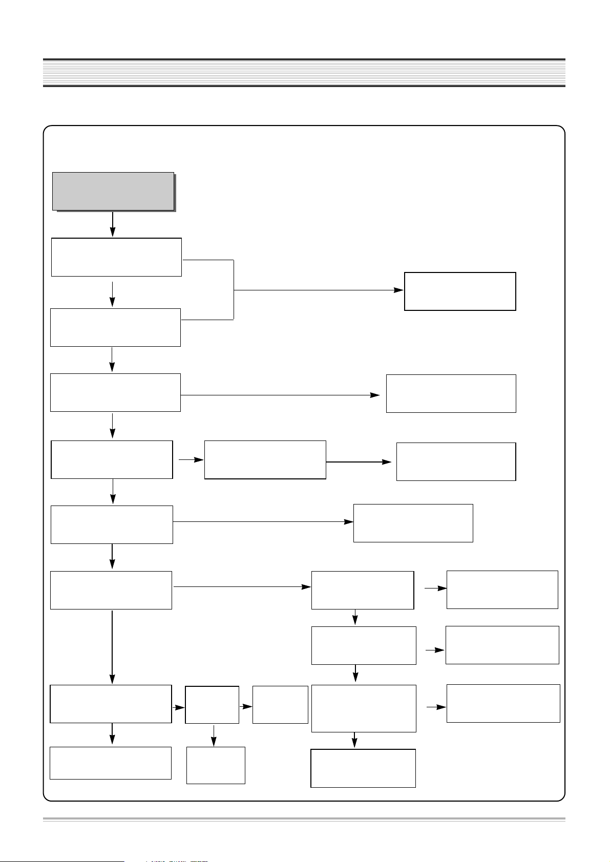
TROUBLESHOOTING
Noise appears on the Full
playback screen.
Are SW pulse and HA SW
normal?
Recheck step C-1 (Bad
playback quallty (1)).
Check HEAD AMP connector
and HEAD.
YES
YES
NO
NO
ENVE Wave at PT01 pin #4?
Check VIDEO circuit.
Are there SW, HA SW pulse at
IC601 pin #16, 18?
Check PCB Pattern.
Check IC601.
C-2. Bad playback quality (2)
No broadcasting signal
received
Is the output at IC601 pin#
71(CLK), 72 (DATA) normal?
Is SIF,Video output at
TMI(RF101) pin#18,20 normal?
Check IC 601.
Check IC301.
Check IC601.
YES
YES
NO
NO
NO
Is Video Signal input at IC601
pin#50?
Is there Video output at IC601
pin#52?
Check TMI (RF101) Block.
NO
Check Video Buffer Q101
D. No broadcasting signal received
YES
YES
NO
YES
YES
YES
9
TROUBLESHOOTING
Cassette tape isn’t
inserted.
Is 5V voltage obtained at
Loading parts IC604 pin#82?
Is 13V voltage obtained at
Capstan Motor pin#8?
Check at ON/OFF 12.
Check (D822, Q821).
Connect Capstan and Loading Motor.
Check connector and Capstan Motor.
YES
NO
NO
NO
Is 12V voltage obtained at Each
parts of Loading Motor?
Replace Loading Motor.
Check D851 and POWER circuit.
E. No CASSETTE Loading
YES
YES
F. AUTO STOP in Playback mode
VCR stops automatically
in playback mode.
Check R656,C659 and P603 pin#11
Check P502 connector.
Check S603, S604 REEL Sensor.
Is D.PG/FG pulse at IC601
pin#90 normal ?
Is C. FG pulse at IC601
pin#87 normal ?
Is there REEL Pulse at IC601
pin#79, 80?
Check and replace IC601.
NO
YES
YES
YES
NO
Check C.FG(R665, C660)
and P603 pin#1.
NO
10
TROUBLESHOOTING
G. DRUM Motor stops
H. CAPSTAN doesn’t rotate
CAPSTAN doesn’t rotate.
Is 14V voltage obtained
at P603 pin#2?
YES
NO
NO
NO
YES
YES
Is Capstan PWM fit to
IC 601 pin#77?
Is 3.2V voltage obtained
at P603 pin#5?
Is 2~3V voltage obtained
at P603 pin#9?
Check P603 Connector and
Capstan Motor.
Check 14V.
(Q856,Q857,Q852)
Check Capstan FG
(IC 601 87).
Check R665, R664, R663,
R666, C665.
Check R661, R667, C664.
DRUM Motor stops.
Is 13V voltage obtained at
P603 pin#8?
YES
NO
NO
NO
YES
YES
Is DRUM PWM fit to IC 601
pin#76?
Is 1.2V voltage obtained at
P603 pin#12?
Check Capstan Motor and
DRUM Motor.
Check ON/OFF 13V
(D851, Q856).
Check DRUM PG/FG(IC 601 90).
Check R657, R658,C661,C668.
NO
11
TROUBLESHOOTING
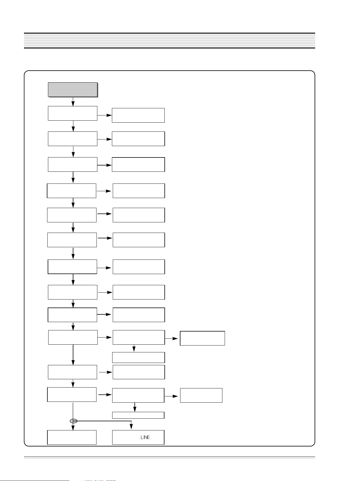
3. VIDEO circuit
A. EE screen doesn’t appear
EE screen doesn’t appear.
Is Video signal input at IC301
pin#48,50,52,54?
Is 5V obtained at IC301
pin#54, 42, 55, 72?
Is signal output at IC301
pin#65?
Is signal input at IC601
pin#50?
Check LINE JACK and IF circuit.
Check DVD circuit.
Check POWER 5V.
Check IC301
pin #70,62,68,69.
NO
YES
YES
YES
NO
NO
NO
Check PCB Pattern.
YES
Is signal output at IC301
pin#61 or #63?
YES
NO
Check IC301
pin #68,69,70,62
Signal output at IC301 pin#65 is
transferred to IC301 pin#56?
YES
NO
Check PCB Pattern.
Is signal input at IC302
pin#12 or #13?
YES
NO
Check PCB Pattern.
Is signal input at IC302
pin#14?
YES
NO
Check IC302 pin #11
Is Y signal input at IC604
pin#6?
YES
NO
Check PCB Pattern.
Is C-Sync signal output at
IC604 pin#3?
YES
NO
Is 5V obtained at IC604
pin#7?
Is C-Sync signal input at
IC601 pin#58?
YES
NO
Check PCB Pattern.
Is C-Sync signal input at IC601
pin#58?
YES
Check PCB Pattern.
NO
Is signal output at IC601
pin# 52?
Is 5V obtained at IC601
pin#53,98,99?
YES
NO
Check POWER circuit.
Check RF Output.
Check
NO
Check IC 601
YES
YES
12
TROUBLESHOOTING
B. Playback picture doesn’t appear
YES
YES
Is Y signal output at IC301
pin#46?
Is Y signal input at IC301
pin#43?
Is Video signal output at IC301
pin#61?
Check and Replace IC301.
Check PCB Pattern.
Playback picture doesn’t
appear.
Is Envelope output at IC301
pin#79?
NO
NO
YES
Check Sync separate circuit
and OSD circuit
Is 5V obtained at IC301
pin#91?
Is SW Pulse input at IC301
pin#70?
Is 5V obtained at IC301
pin#21, 57?
Check POWER 5V.
Check IC601 pin#18.
Check and Replace HEAD.
Check POWER 5V.
YES
NO
NO
Does X301(3.58MHz) oscillate?
Check Pattern.
NO
NO
NO
YES
NO
NO
YES
YES
YES
YES
Replace X301.
Is Video signal output at IC301
pin#65?
Check IC301 pin# 62.68,69,70.
NO
YES
13
TROUBLESHOOTING
Is 5V obtained at IC301
pin#91?
YES
NO
NO
NO
YES
YES
Is IC301 pin#80 PB(H) LOW?
Is VIDEO SW Pulse input at
IC301 pin#70?
Is REC signal input at IC301
pin#94, 95, 89, 90?
EP MODE: 89, 90 Pin
SP MODE: 94,95Pin
Check HEAD and Connector.
Is signal input at IC301 pin#
48, 50, 52, 54?
Check POWER circuit.
Check PB(H) circuit
Check IC601 pin#18.
No recording.
Check EE MODE.
YES
Is FM signal output at IC301
pin#78?
Replace IC301.
NO
NO
YES
C. No recording
14
TROUBLESHOOTING
E. No sound in broadcasting (Stereo)
Is 5V obtained at IC101
pin#1, 11, 33?
Oscillation of IC101 pin#5,6?
YES
NO
NO
NO
YES
YES
Is SIF output from RF101
pin#18 to IC101 pin#2?
Is AUDIO output at IC101
pin#26, 27?
Check IC251 pin#2,3.
Check POWER circuit.
Exchange X101.
Check RF101.
Exchange IC101.
NO
NO
Is Video signal input at IC601
pin#50?
Check POWER circuit.
No OSD appears.
Is 5V obtained at IC601 pin#
53, 98, 99?
Is Video signal output at IC601
pin#52?
NO
Replace IC601.
D. No OSD(On Screen Display) appears
YES
YES
NO
Check IC 601.
Check IC 601.
15
TROUBLESHOOTING
4. AUDIO
No sound in RF E-E
mode
Is there Audio at IC252
pin#5,14?
IC601 pin#27
A.Mute is L or
H?
A. No sound in E-E mode
A. a.1 RF E-E
NO
Check signal flow circuit
from IC251 to IC252.
Is 12V obtained at IC252
pin#16?
Is RF Audio signal output at
IC252 pin#3,13?
Check POWER circuit.
NO
YES
NO
IC601 pin#20 is H,
pin#21is L?
Is about 3.5V obtained at
IC252 pin#9?
Is about 8V obtained at
pin #10?
YES
Check IC601.
Check
R298,R299,R646,R647.
NO
NO
C at Q258 is L or H?
YES
Check IC601.
Check Output JACK.
H
H
L
YES
Is Audio signal output at IC251
pin#19, 20?
Are CLK and DATA obtained
at IC251 pin#42,43?
NO
Is 5V obtained at IC251
pin#40?
Is there Audio at IC251 pin#2,
3 in RF mode?
Check IC101 and RF101
Block(Ad2).
NO
Replace IC251.
NO
YES
YES
Is 12V obtained at IC251
pin#34?
NO
YES
Check POWER circuit.
YES
Check
Q257,Q258,R24
0, R241, R242
L
Replace IC252
YES
16
TROUBLESHOOTING
Is there Audio IC252 pin#5, 14?
IC601 pin#27
A.Mute is L or
H?
A. b. LINE1 E-E
YES
NO
Check signal flow circuit from
IC251 to IC252.
Is 12V obtained at IC252
pin 16?
Is RF Audio signal output at
IC252 pin#3,13?
Check POWER circuit.
YES
NO
IC601 pin#20 is H,
pin#21is L?
Is about 3.5V obtained
at IC252 pin#9?
Is about 8V obtained at
pin #10?
YES
Replace IC252.
Check IC601.
Check R298, R299, R646,
R647.
NO
NO
NO
C at Q258 is L or H?
YES
Check
IC601.
Check Output JACK.
Check
Q257,Q258,R2
40,R241,R242.
H
H
L
L
YES
YES
No sound in LINE1 E-E
mode.
Is 12V obtained at IC251
pin#34?
NO
Is 5V obtained at IC251
pin#40?
Check POWER circuit.
YES
NO
Are CLK and DATA obtained at
IC251 pin#42,43?
Check Input LINE1
JACK
Replace IC251
NO
Is Audio signal output at IC251
pin#19, 20?
Is Audio signal at IC251
pin#6, 7 in LINE1 mode?
17
TROUBLESHOOTING
Is there Audio at IC252
pin#4,11 in LINE2 mode?
IC601 pin#27
A.Mute is L or
H?
NO
Check Input LINE2 JACK.
Is 12V obtained at IC252
pin#16?
Is LINE2 Audio signal output
at IC252 pin#3,13?
Check POWER circuit.
NO
YES
NO
IC601 pin#20 is H?
pin21 is H?
Is about 8V obtained at
IC252 pin#9? Is about 8V
obtained at pin#10 ?
Replace IC252.
Check IC601.
Check
R298,R299,R646,R647.
NO
NO
C at Q258 is L or H?
YES
Check
IC601.
Check Output JACK.
Check
Q257,Q258,R2
40,R241,R242.
H
H
L
L
YES
YES
YES
A. c. LINE2 E-E
No sound in LINE2 E-E
mode.
 Loading...