


SF302-08
Quick Start Guide
Cisco Small Business
300 Series Managed Switches

2 300 Series Managed Switches
Welcome
Thank you for choosing the Cisco 300 Series Managed Switch, a Cisco
Small Business network communications device. This device is designed
to be operational right out of the box as a standard bridge. In the default
configuration, it will forward packets between connecting devices after
power up.
Package Contents
• Cisco SF 300-08, SF 302-08, SF 302-08MP, SF 302-08P, SG 300-10,
SG 300-10MP, SG 300-10P, SG 300-20, SF 300-24, SF 300-24P, SG
300-28, SG 300-28P, SF 300-48, SF 300-48P, or SG 300-52 Managed
Switch
• Rackmount Kit
• Wall Mount Kit
• Power Cord (power adapter included with 8-port devices)
• This Quick Start Guide
• Product CD
• Serial Cable
• Rubber Feet
This guide will familiarize you with the layout of the managed switch and
describe how to deploy the device in your network. For additional
information, see www.cisco.com/smb.
Mounting the Cisco Switch
There are three ways to physically install the switch:
• Set the switch on a flat surface.
• Mount the switch on a wall (8-port devices only).
• Mount the switch in a standard rack (1 rack unit high).
Do not deploy the device in a location where any of the following
conditions exist:
High Ambient Temperature—The ambient temperature must not
exceed 104 degrees Fahrenheit (40 degrees Centigrade).
Reduced Air Flow—Both side panels must be unobstructed to prevent
overheating.
1
300 Series Managed Switches 3
Mechanical Overloading—The device should be level, stable, and
secure to prevent it from sliding or shifting out of position.
Circuit Overloading—Adding the device to the power outlet must not
overload that circuit.
Rack-Mount Placement
To rack-mount the switch in any standard rack, attach the rack–mount
brackets to the sides of the switch with the supplied hardware and secure
the brackets tightly.
CAUTION For stability, load the rack from the bottom to the top, with the
heaviest devices on the bottom. A top-heavy rack is likely to
be unstable and may tip over.
Wall Mounting
Only the 8-port models of the switch can be wall-mounted.
NOTE The switch should be mounted so that the ports face up or down.
Do not mount the switch with the ports to the side.
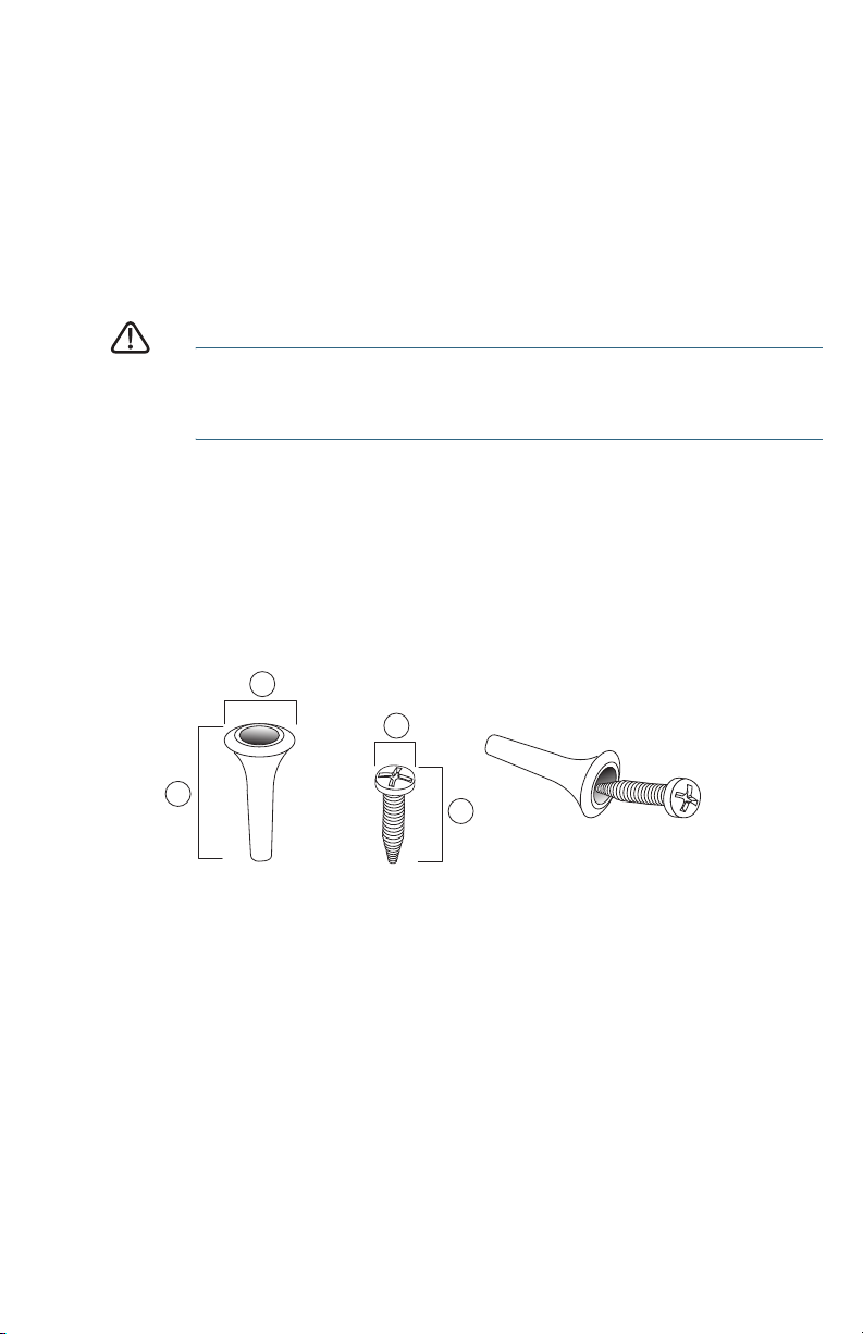
There is a wall-mount kit packed with your switch. The dimensions for the
mount kit are as follows:
Mount the managed switch to the wall by drilling two pilot holes
3.7 inches (95 mm) apart, attaching the provided anchors and screws to
the wall, then sliding the switch into position on the screws.
The switch should have a minimum of 5 inches (130 mm) of clearance on all
sides.
1 8 mm/0.4 in 2 22.2 mm/0.9 in 3 6.8 mm/0.3 in 4 17.6 mm/0.7 in
1
2
4
3
4 300 Series Managed Switches
WARNING Insecure mounting may damage the device or cause injury.
Cisco is not responsible for damages incurred by insecure wall-
mounting.
Connecting Network Devices
To connect the managed switch to the network:
STEP 1 Connect the Ethernet cable to the Ethernet port of a computer,
printer, network storage, or other network device.
STEP 2 Connect the other end of the network Ethernet cable to one of the
numbered managed switch Ethernet ports.
The LED of the port lights if the device connected is active. Refer to
Features of the Cisco Small Business Managed Switch, page 9
for details about the different ports and LEDs on each switch.
STEP 3 Repeat Step 1 and Step 2 for each device you want to connect to
the managed switch.
NOTE Cisco strongly recommends using Cat5 or better cable for Gigabit
connectivity. When you connect your network devices, do not exceed
the maximum cabling distance of 100 meters (328 feet). It can take up to
one minute for attached devices or the LAN to be operational after it is
connected. This is normal behavior.
Power over Ethernet (PoE) Considerations
If your switch is one of the PoE models, consider the following:
As a PSE (Power Sourcing Equipment) device, the switch can deliver a
maximum of 15.4 Watts per PoE port to a PD (Powered Device).
2

300 Series Managed Switches 5
Configuring the Cisco Small Business
Managed Switch
Before You Begin
Verify that a computer with Microsoft Internet Explorer (version 6 and
higher) or Firefox (version 2.0 or higher) is available.
The switch can be accessed and managed by two different methods; over
your IP network using the web-based interface, or by the menu CLI
through the console port. Using the console port requires advanced user
skills.
The switch works with Cisco Small Business network tools and services
including the Cisco FindIT Network Discovery Utility that enables you to
automatically discovers all supported Cisco Small Business devices in the
same local network segment as your PC. You can get a snapshot view of
each device or launch the product configuration utility to view and
configure the settings. For more information, see www.cisco.com/go/findit.
Accessing and Managing Your Switch Using the Web-
Based Interface
In order to access the switch with a web-based interface, you will need to
know the IP address the switch is using. The default configuration of the
switch is to use its factory default IP address of 192.168.1.254 until it has
obtained an IP address from a DHCP server.
When the switch is using the factory default IP address, its power LED
flashes continuously. When the switch is using a DHCP assigned IP
address or an administrator configured static IP address, the power LED is
on solid.
NOTE If the managed switch IP address is changed, either by a DHCP
server or manually, your access to the managed switch will be lost and
you must enter the new IP address to use the web-based interface.
Use the Web-Based Interface
To configure the managed switch:
STEP 1 Power on the computer and the switch.
STEP 2 Connect the computer to the switch. You can connect to the same
IP subnet as the switch by connecting them directly with an
Ethernet cable, or by connecting to the same LAN where the
switch is located through other switches. You can also connect
your computer to the switch from another IP subnet through one or
more IP routers.
3
 Loading...