


SF250
Table of contents
 Loading...
ADMINISTRATION
GUIDE
Cisco Sx250 Series Managed Switches, Firmware Release
2.2.5.x

Contents
Chapter 1: Getting Started 8
Starting the Web-based Configuration Utility 8
USB Port 12
Basic or Advanced Display Mode 12
Quick Start Device Configuration 14
Interface Naming Conventions 14
Window Navigation 16
Search Facility 19
Chapter 2: Dashboard 20
Grid Management 20
System Health 22
Resource Utilization 23
Identification 24
Port Utilization 25
PoE Utilization 26
Latest Logs 27
Suspended Interfaces 27
Traffic Errors 28
Chapter 3: Configuration Wizards 30
Getting Started Wizard 30
VLAN Configuration Wizard 32
Chapter 4: Status and Statistics 34
System Summary 34
CPU Utilization 36
Interface 37
Etherlike 38
Port Utilization 39
Cisco Sx250 Series Managed Switches, Firmware Release 2.2.5.x 1

Contents
802.1X EAP 40
Health and Power 41
Switched Port Analyzer (SPAN) 45
Diagnostics 47
RMON 51
View Logs 59
Chapter 5: Administration 61
Device Models 61
System Settings 62
User Accounts 63
Idle Session Timeout 64
Time Settings 64
System Log 65
File Management 68
Reboot 68
Discovery - Bonjour 70
Discovery - LLDP 70
Discovery - CDP 70
Ping 70
Chapter 6: Administration: File Management 73
System Files 73
Firmware Operations 75
File Operations 78
File Directory 86
DHCP Auto Configuration/Image Update 86
Chapter 7: Administration: Time Settings 96
System Time Configuration 97
Cisco Sx250 Series Managed Switches, Firmware Release 2.2.5.x 2

Contents
SNTP Modes 98
System Time 99
SNTP Unicast 101
SNTP Multicast/Anycast 103
SNTP Authentication 104
Chapter 8: Administration: Discovery 106
Bonjour 106
LLDP and CDP 107
Discover - LLDP 109
Discovery - CDP 129
Chapter 9: Port Management 140
Workflow 140
Port Settings 141
Error Recovery Settings 144
Loopback Detection Settings 145
Link Aggregation 147
PoE 155
Green Ethernet 164
Chapter 10: Smartport 172
Overview 172
How the Smartport Feature Works 177
Auto Smartport 177
Error Handling 181
Default Configuration 181
Relationships with Other Features 182
Common Smartport Tasks 182
Configuring Smartport Using The Web-based Interface 184
Cisco Sx250 Series Managed Switches, Firmware Release 2.2.5.x 3

Contents
Built-in Smartport Macros 189
Chapter 11: VLAN Management 200
Overview 200
Regular VLANs 202
Voice VLAN 209
Chapter 12: Spanning Tree 222
STP Flavors 222
STP Status and Global Settings 223
STP Interface Settings 225
RSTP Interface Settings 227
Multiple Spanning Tree Overview 229
MSTP Properties 229
VLANs to a MSTP Instance 230
MSTP Instance Settings 231
MSTP Interface Settings 232
Chapter 13: Managing MAC Address Tables 235
Static Addresses 236
Dynamic Addresses 237
Chapter 14: Multicast 238
Multicast Forwarding Overview 238
Properties 243
MAC Group Address 244
IP Multicast Group Address 245
IPv4 Multicast Configuration 247
IPv6 Multicast Configuration 250
IGMP/MLD Snooping IP Multicast Group 253
Cisco Sx250 Series Managed Switches, Firmware Release 2.2.5.x 4

Contents
Multicast Router Port 254
Forward All 254
Unregistered Multicast 255
Chapter 15: IP Configuration 258
Overview 258
IPv4 Management and Interfaces 260
IPv6 Management and Interfaces 264
Domain Name System 275
Chapter 16: Security 281
RADIUS 282
Password Strength 285
Management Access Method 287
Management Access Authentication 291
SSL Server 293
SSH Client 295
TCP/UDP Services 295
Storm Control 296
Port Security 300
802.1X Authentication 302
Denial of Service Prevention 302
Chapter 17: Security: 802.1X Authentication 306
Overview 306
Properties 313
Port Authentication 314
Host and Session Authentication 316
Authenticated Hosts 317
Cisco Sx250 Series Managed Switches, Firmware Release 2.2.5.x 5

Contents
Chapter 18: Security: Secure Sensitive Data Management 318
Introduction 318
SSD Management 319
SSD Rules 319
SSD Properties 324
Configuration Files 327
SSD Management Channels 331
Menu CLI and Password Recovery 332
Configuring SSD 332
Chapter 19: Security: SSH Client 336
Overview 336
SSH User Authentication 342
SSH Server Authentication 343
Change User Password on the SSH Server 345
Chapter 20: Quality of Service 346
QoS Features and Components 347
General 348
QoS Statistics 356
Chapter 21: SNMP 358
Overview 358
Engine ID 361
Views 363
Groups 364
Users 365
Communities 367
Trap Settings 369
Notification Recipients 370
Cisco Sx250 Series Managed Switches, Firmware Release 2.2.5.x 6

Contents
Notification Filter 374
Cisco Sx250 Series Managed Switches, Firmware Release 2.2.5.x 7

Getting Started
This section provides an introduction to the web-based configuration utility, and covers the
following topics:
1
• Starting the Web-based Configuration Utility
• USB Port
• Basic or Advanced Display Mode
• Quick Start Device Configuration
• Interface Naming Conventions
• Window Navigation
• Search Facility
Starting the Web-based Configuration Utility
This section describes how to navigate the web-based switch configuration utility.
If you are using a pop-up blocker, make sure it is disabled.
Browser Restrictions
If you are using IPv6 interfaces on your management station, use the IPv6 global address and
not the IPv6 link local address to access the device from your browser.
Cisco Sx250 Series Managed Switches, Firmware Release 2.2.5.x 8

1
Getting Started
Starting the Web-based Configuration Utility
Launching the Configuration Utility
To open the web-based configuration utility:
STEP 1 Open a Web browser.
STEP 2 Enter the IP address of the device you are configuring in the address bar on the browser, and
then press Enter.
NOTE When the device is using the factory default IP address of 192.168.1.254, its system LED
flashes continuously. When the device is using a DHCP-assigned IP address or an
administrator-configured static IP address, the system LED is on solid.
The default IP address 192.168.1.254 is configured on the default VLAN (VLAN 1).
Logging In
The default username/password is cisco/cisco. The first time that you log in with the default
username and password, you are required to enter a new password.
NOTE If you have not previously selected a language for the GUI, the language of the Login page is
determined by the language(s) requested by your browser and the lang uages configured on your
device. If your browser requests Chinese, for example, and Chinese has been loaded into your
device, the Login page is automatically displayed in Chinese. If Chinese has not been loaded
into your device, the Login page appears in English.
The languages loaded into the device have a language and country code (en-US, en-GB and so
on). For the Login page to be automatically displayed in a particular language, based on the
browser request, both the language and country code of the browser request must match those
of the language loaded on the device. If the browser request contains only the language code
without a country code (for example: fr). The first embedded language with a matching
language code is taken (without matching the country code, for example: fr_CA).
To log in to the device configuration utility:
STEP 1 Enter the username/password. The password can contain up to 64 ASCII characters.
Password-complexity rules are described in Password Strength.
STEP 2 If you are not using English, select the desired langu age from the Lang uage drop -down menu.
To add a new language to the device or update a current one, see the description of the
Language Menu described in Application Header.
Cisco Sx250 Series Managed Switches, Firmware Release 2.2.5.x 9

Getting Started
Starting the Web-based Configuration Utility
STEP 3 If this is the first time that you logged on with the default user ID (cisco) and the default
password (cisco) or your password has expired, the Change Password Page appears. See
Password Expiration for additional information.
STEP 4 Choose whether to select Password Complexity Settings in the Password Strength page.
STEP 5 Enter the new password and click Apply.
When the login attempt is successful, the Getting Started page appears.
If you entered an incorrect username or password, an error message appears and the Login
page remains displayed on the window.
Select Don't show this page on startup to prevent the Getting Started page from being
displayed each time that you log on to the system. If you select this option, the System
Summary page is opened instead of the Getting Started page.
1
HTTP/HTTPS
You can either open an HTTP session (not secured) by clicking Log In, or you can open an
HTTPS (secured) session, by clicking Secure Browsing (HTTPS). You are asked to approve
the logon with a default RSA key, and an HTTPS session is opened.
NOTE There is no need to input the username/password prior to clicking the Secure Browsing
(HTTPS) button.
For information on how to configure HTTPS, see SSL Server.
Password Expiration
The New Password page is displayed in the following cases:
• The first time that you access the device with the default username cisco and password
cisco. This page forces you to replace the factory default password.
• When the password expires, this page forces you to select a new password.
Logging Out
By default, the application logs out after ten minutes of inactivity. You can change this default
value as described in the Defining Idle Session Timeout section.
Cisco Sx250 Series Managed Switches, Firmware Release 2.2.5.x 10

1
Getting Started
Starting the Web-based Configuration Utility
!
CAUTION Unless the Running Configuration is copied to the Startup Configuration, rebooting the device
removes all changes made since the last time the file was saved. Save the Running
Configuration to the Startup Configuration before log ging off to preserve any changes you
made during this session.
A flashing red X icon to the left of the Save application link indicates that Running
Configuration changes have not yet been saved to the Startup Configuration file. The flashing
can be disabled by clicking on the Disable Save Icon Blinking button on the Copy/Save
Configuration page
When the device auto-discovers a connected device, such as an IP phone (see What is a
Smartport), and it configures the port appropriately for the device. These configuration
commands are written to the Running Configuration file. This causes the Save icon to begin
blinking when the you log on, even though you did not make any configuration changes.
When you click Save, the Copy/Save Configuration page appears. Save the Running
Configuration file by copying it to the Startup Configuration file. After this save, the red X icon
and the Save application link are no longer displayed.
To logout, click Logout in the top right corner of any page. The system logs out of the device.
When a timeout occurs or you intentionally log out of the system, a message is displayed and
the Login page appears, with a message indicating the logged-out state. After you log in, the
application returns to the initial page.
The initial page displayed depends on the “Do not show this page on startup” option in the
Getting Started page. If you did not select this option, the initial page is the Getting Started
page. If you did select this option, the initial page is the System Summary page.
Layer 2 Applications
The following Layer 2 applications are supported on the OOB port, however functionality may
differ from functionality on inband ports:
• 802.1x
• LLDP
• CDP
Cisco Sx250 Series Managed Switches, Firmware Release 2.2.5.x 11
Getting Started
USB Port
USB Port
1
The USB port can be used for connecting external storage (disk-on-key) devices. It can hold
configuration, SYSLOG and image files. The USB port fully supports the FAT32 file system,
and provides partial support (read only) for the NTFS file system.
Both relative path or fully qualified paths can be used.
The system supports the following user actions on the USB port through the GUI:
• Display the USB contents
• Copy files to/from USB (the same as with TFTP)
• Delete, rename and display the contents of USB files
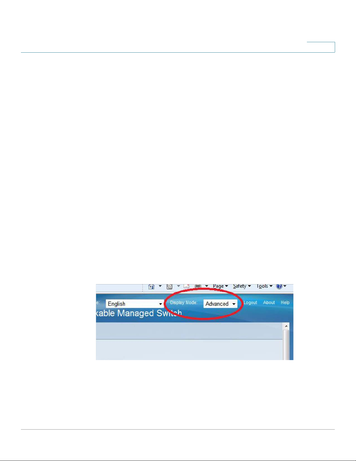
Basic or Advanced Display Mode
The product supports many features, and therefore the WEB GUI includes hundreds of
configuration and display pages. These pages are divided into the following display modes:
• Basic—Basic subset of configuration options are available. If you are missing some
configuration option, select the Advanced mode in the device header.
• Advanced—Full set of configuration options are available.
Navigate from one mode to another, as shown below:
When the user switches from basic to advanced, the browser reloads the page. However, after
reload, the user stays on the same page.
Cisco Sx250 Series Managed Switches, Firmware Release 2.2.5.x 12

1
Getting Started
Basic or Advanced Display Mode
When the user switches from advanced to basic, the browser reloads the page. If the page
exists also on the basic mode, the user stays on the same page. If the page does not exist in the
basic mode, the browser will load the first page of the folder which was used by the user . If the
folder does not exist, the Getting Started page will be displayed.
If there is advanced configuration, and the page is loaded in basic mode, a page-level message
will be displayed to the user (e.g. there are 2 radius server configured but in basic mode only a
single server can be displayed, or there is 802.1X port authentication with time range
configured but time range is not visible in basic mode).
When switching from one mode to another, any configuration which was made on the page
(without Apply) is deleted.
Cisco Sx250 Series Managed Switches, Firmware Release 2.2.5.x 13

Getting Started
Quick Start Device Configuration
Quick Start Device Configuration
For quick initial setup, you can use the configuration wizards described in VLAN
Configuration Wizard or use the links on the Getting Started page, as described below:
Category Link Name (on the Page) Linked Page
1
Initial Setup
Device Status System Summary System Summary
Quick Access Change Device Password User Accounts
Change Management Applicatio ns
and Services
Change Device IP Address IPv4 Interface
Create VLAN VLAN Settings
Configure Port Settings Port Settings
Port Statistics Interface
RMON Statistics Statistics
Vi ew Log RAM Memory
Upgrade Device Software Firmware Operations
Backup Device Configuration File Operations
Configure QoS QoS Properties
Configure SPAN Switched Port Analyzer (SPAN)
TCP/UDP Services
There are two hot links on the Getting Started page that take you to Cisco web pages for more
information. Clicking on the Support link takes you to the device product support page, and
clicking on the Forums link takes you to the Support Community page.
Interface Naming Conventions
Within the GUI, interfaces are denoted by concatenating the following elements:
• Type of interface: The following types of interfaces are found on the various types of
devices:
- Fast Ethernet (10/100 bits)—These are displayed as FE.
Cisco Sx250 Series Managed Switches, Firmware Release 2.2.5.x 14

1
Getting Started
Interface Naming Conventions
- Gigabit Ethernet ports (10/100/1000 bits)—These are displayed as GE.
- Out-of-Band Port—This is displayed as OOB.
- LAG (Port Channel)—These are displayed as LAG.
- VLAN—These are displayed as VLAN.
- Tunnel —These are displayed as Tunnel.
• Interface Number: Port, LAG, Tunnel, or VLAN ID.
Cisco Sx250 Series Managed Switches, Firmware Release 2.2.5.x 15

Getting Started
Window Navigation
Window Navigation
This section describes the features of the web-based switch configuration utility.
Application Header
The Application Header appears on every page. It provides the following application links:
1
Application Link
Name
Username Displays the name of the user logged on to the device. The default
Description
A flashing red X icon displayed to the left of the Save application
link indicates that Running Configuration changes have been made
that have not yet been saved to the Startup Configuration file. The
flashing of the red X can be disabled on the Copy/Save
Configuration page.
Click Save to display the Copy/Save Configuration page. Save the
Running Configuration file by copying it to the Startup
Configuration file type on the device. After this save, the red X
icon and the Save application link are no longer displayed. When
the device is rebooted, it copies the Startup Configuration file type
to the Running Configuration and sets the device parameters
according to the data in the Running Configuration.
username is cisco. (The default password is cisco).
Cisco Sx250 Series Managed Switches, Firmware Release 2.2.5.x 16

1
Getting Started
Window Navigation
Application Link
Name
Language Menu This menu provides the following options:
Logout Click to log out of the web-based switch configuration utility.
Description
• Select a language: Select one of the languages that appear
in the menu. This language will be the web-based
configuration utility language.
• Download Language: Add a new language to the device.
• Delete Language: Deletes the second language on the
device. The first language (English) cannot be deleted.
• Debug: Used for translation purposes. If you select this
option, all web-based configuration utility labels disappear
and in their place are the IDs of the strings that correspond
to the IDs in the language file.
NOTE T o upgrad e a language file, use the Upgrade/Backup
Firmware/Language page.
About Click to display the device name and device version number.
Help Click to display the online help.
The SYSLOG Alert Status icon appears when a SYSLOG message,
above the critical severity level, is logged. Click the icon to open
the RAM Memory page. After you access this page, the SYSLOG
Alert Status icon is no longer displayed. To display the page when
there is not an active SYSLOG message, Click Status and
Statistics > View Log > RAM Memory.
Cisco Sx250 Series Managed Switches, Firmware Release 2.2.5.x 17

Getting Started
Window Navigation
1
Management Buttons
The following table describes the commonly-used buttons that appear on various pages in the
system.
Button Name Description
Use the pull-down menu to configure the number of entries per
page.
Indicates a mandatory field.
Add Click to display the related Add page and add an entry to a table.
Enter the information and click Apply to save it to the Running
Configuration. Click Close to return to the main page. Click Save
to display the Copy/Save Configuration page and save the Running
Configuration to the Startup Configuration file type on the device.
Apply Click to apply changes to the Running Configuration on the device.
If the device is rebooted, the Running Configuration is lost, unless
it is saved to the Startup Configuration file type or another file
type. Click Save to display the Copy/Save Configuration page and
save the Running Configuration to the Startup Configuration file
type on the device.
Cancel Click to reset changes made on the page.
Clear Filter Click to clear filter to select information displayed.
Clear All Interfaces
Counters
Clear Interface
Counters
Clear Logs Clears log files.
Clear Table Clears table entries.
Close Returns to main page. If any changes were not applied to the
Click to clear the statistic counters for all interfaces.
Click to clear the statistic counters for the selected interface.
Running Configuration, a message appears.
Cisco Sx250 Series Managed Switches, Firmware Release 2.2.5.x 18

1
Getting Started
Search Facility
Button Name Description
Copy Settings A table typically contains one or more entries containing
configuration settings. Instead of modifying each entry
individually, it is possible to modify one entry and then copy the
selected entry to multiple entries, as described below:
1. Select the entry to be copied. Click Copy Settings to display the
popup.
2. Enter the destination entry numbers in the to field.
3. Click Apply to save the changes and click Close to return to the
main page.
Delete After selecting an entry in the table, click Delete to remove.
Details Click to display the details associated with the entry selected.
Search Facility
Edit Select the entry and click Edit. The Edit page appears, and the
entry can be modified.
1. Click Apply to save the changes to the Running Configuration.
2. Click Close to return to the main page.
Go Enter the query filtering criteria and click Go. The results are
displayed on the page.
Refresh Click Refresh to refresh the counter values.
Test Click Test to perform the related tests.
Restore Defaults Click Restore Defaults to restore factory defaults.
The search function helps the user to locate relevant GUI pages.
The search result for a keyword includes links to the relevant pages, and also links to the
relevant help pages.
To access the search function, enter a key word and click on the magnifyi ng glass icon.
Cisco Sx250 Series Managed Switches, Firmware Release 2.2.5.x 19

Dashboard
2
The dashboard is a collection of 8 squares, initially empty, that can be populated by various
types of information
You can select a number of modules from the available modules and place them in this grid.
You can also customize settings of the currently-displayed modules.
When the dashboard loads, the modules you selected for the dashboard are loaded in their
locations in the grid. The data in the modules is updated periodically , in intervals depending on
the module type. These intervals are configurable for some modules.
This following topics are covered in this chapter:
• Grid Management
Grid Management
• System Health
• Resource Utilization
• Identification
• Port Utilization
• PoE Utilization
• Latest Logs
• Suspended Interfaces
• Traffic Errors
The dashboard consists of multiple modules, but only a subset of the modules can be viewed at
the same time.
Cisco Sx250 Series Managed Switches, Firmware Release 2.2.5.x 20
2
Dashboard
Grid Management
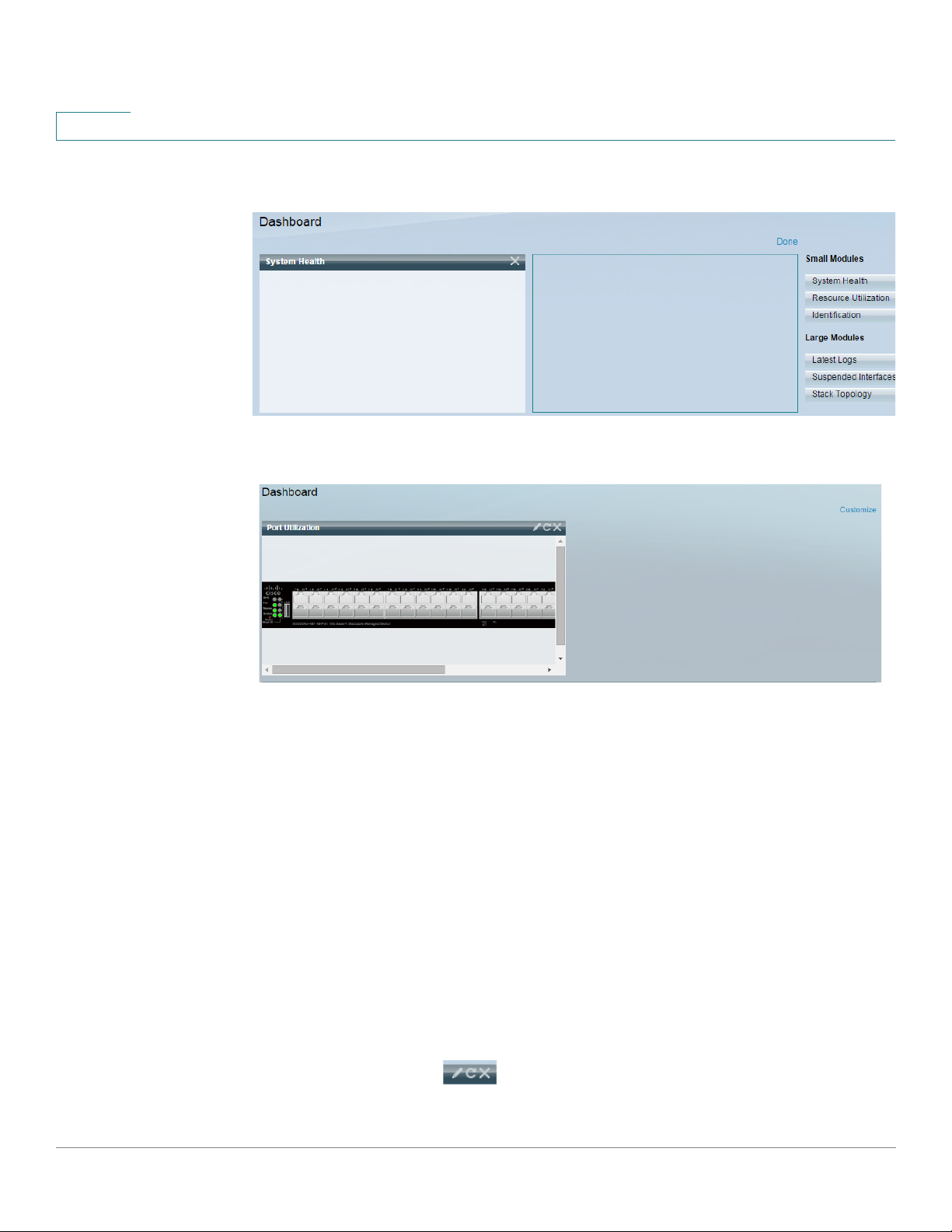
When you open the dashboard, a wire frame view of the grid is displayed, as shown below
(only 2 squares are shown in the following screen capture):
To display modules that are not currently being displayed, click on Customize on the upper-
right of the dashboard, as shown below:
Add modules to the grid by selecting a module from the list of modules on the right and
dragging and dropping it to any space in the grid.
The modules are divided into the following groups:
• Small Modules are modules that take up a single square
• Large Modules take up two squares.
If you drag a module into a space currently occupied, the new module replaces the previous
one.
You can re-arrange the placement of the modules in the grid by dragging a module from one
occupied grid position to another position. The module can be dropped in an unoccupied spot,
or in a spot occupied by a module of the same size. If the selected spot is occupied, the
modules switch places.
Only when you click Done (in the right-hand corner), are the modules populated by the
relevant informationThe title bar of each module in the dashboard displays the title of the
module and three buttons:
21 Cisco Sx250 Series Managed Switches, Firmware Release 2.2.5.x
Dashboard
System Health
System Health
2
These button perform the following:
• Pencil — Opens configuration options (depending on the module).
• Refresh — Refreshes the information.
• X — Removes the module from the dashboard.
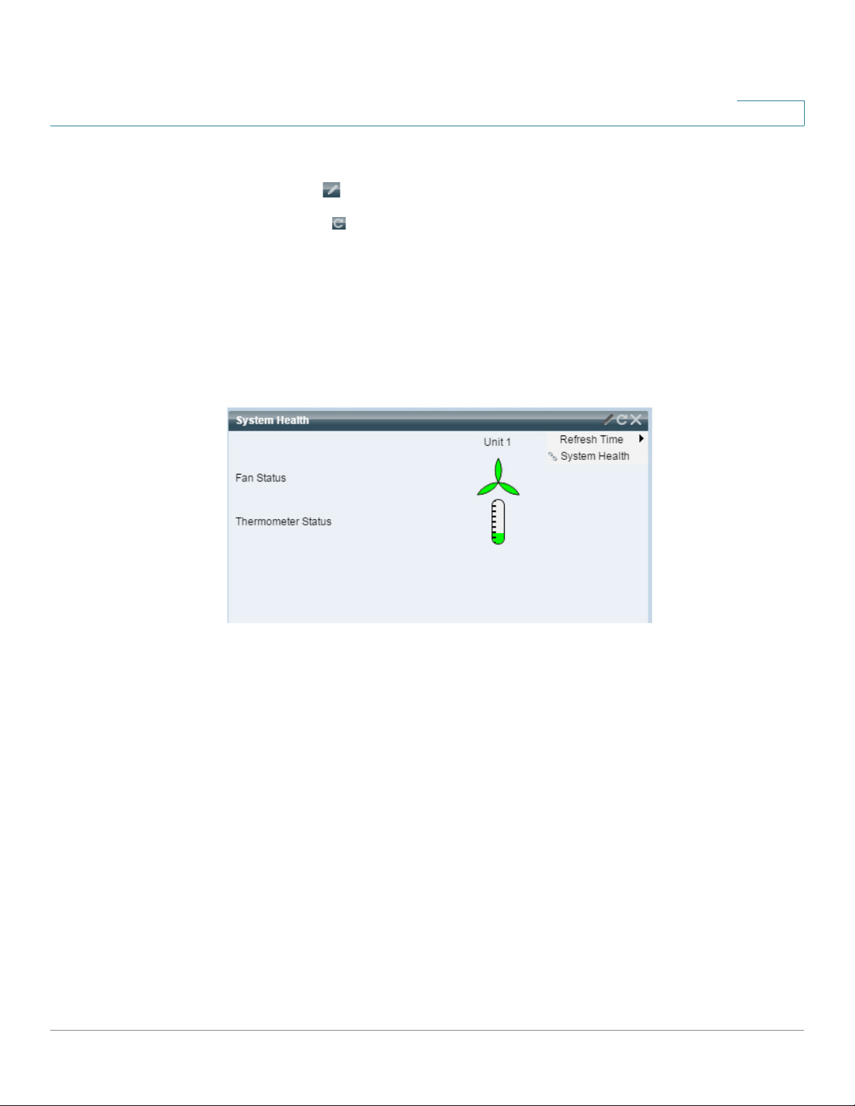
This module displays information about device temperature (when such information is
available) for a device, as shown below:
The following icons are shown:
• Fan Status—Yellow if one fan failed and is backed up by the redundant fan; Green if
the fan is operational; Red if the fan is faulty.
• Thermometer Status
- Temperature is OK—Green with a nearly empty thermometer.
- Temperature generates a warning—Yellow with a half full thermometer.
- Temperature is critical—Red with a full thermometer.
The following configuration options (pencil icon in upper right-hand corner) are available:
• Refresh Time—Select one of the options displayed.
Cisco Sx250 Series Managed Switches, Firmware Release 2.2.5.x 22

2
Resource Utilization
This module displays the utilization status in terms of a percentage of the various system
resources as a bar chart, The resources monitored are:
Each bar becomes red if the resource utilization is higher than 80 percent.
Dashboard
Resource Utilization
• Multicast Groups—Percentage of Multicast groups that exist out of the maximum
possible number that are permitted to be defined.
• MAC Address T able—Percentage of MAC Address table in use.
• Router TCAM—Usage in percentage of router TCAM.
• TCAM—Usage in percentage of all non-IP TCAM entries.
• CPU—Percentage of CPU being used.
Hovering over a bar displays a tooltip displaying the numeric utilization information (used
resources/max available).
The following configuration options (right-hand corner) are available:
• Refresh Time—Select one of the options displayed.
• Multicast Groups—Click to open MAC Group Address
• MAC Address T able—Click to open Dynamic Addresses.
23 Cisco Sx250 Series Managed Switches, Firmware Release 2.2.5.x
Dashboard
Identification
Identification
2
• CPU Utilization Information—Click to open CPU Utilization.
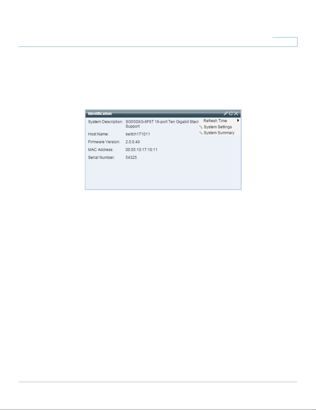
This module displays basic information regarding the device, as shown below:
It displays the following fields:
• System Description—Displays description of the device.
• Host Name—Entered in the System Settings page or default is used. Also can be
added in the Getting Started Wizard.
• Firmware Version—Current firmware version running on device.
• MAC Address—MAC address of the device.
• Serial Number—Serial number of the device.
• System Location—Enter the physical location of the device.
• System Contact—Enter the name of a contact person.
• T otal Available Power—Amount of power available to the device.
• Current Power Consumption—Amount of power consumed by the device.
The following configuration options (right-hand corner) are available:
• Refresh Time—Select one of the options displayed.
Cisco Sx250 Series Managed Switches, Firmware Release 2.2.5.x 24
2
Port Utilization
Dashboard
Port Utilization
• System Settings—Click to open System Settings.
• System Summary—Click to open System Summary.
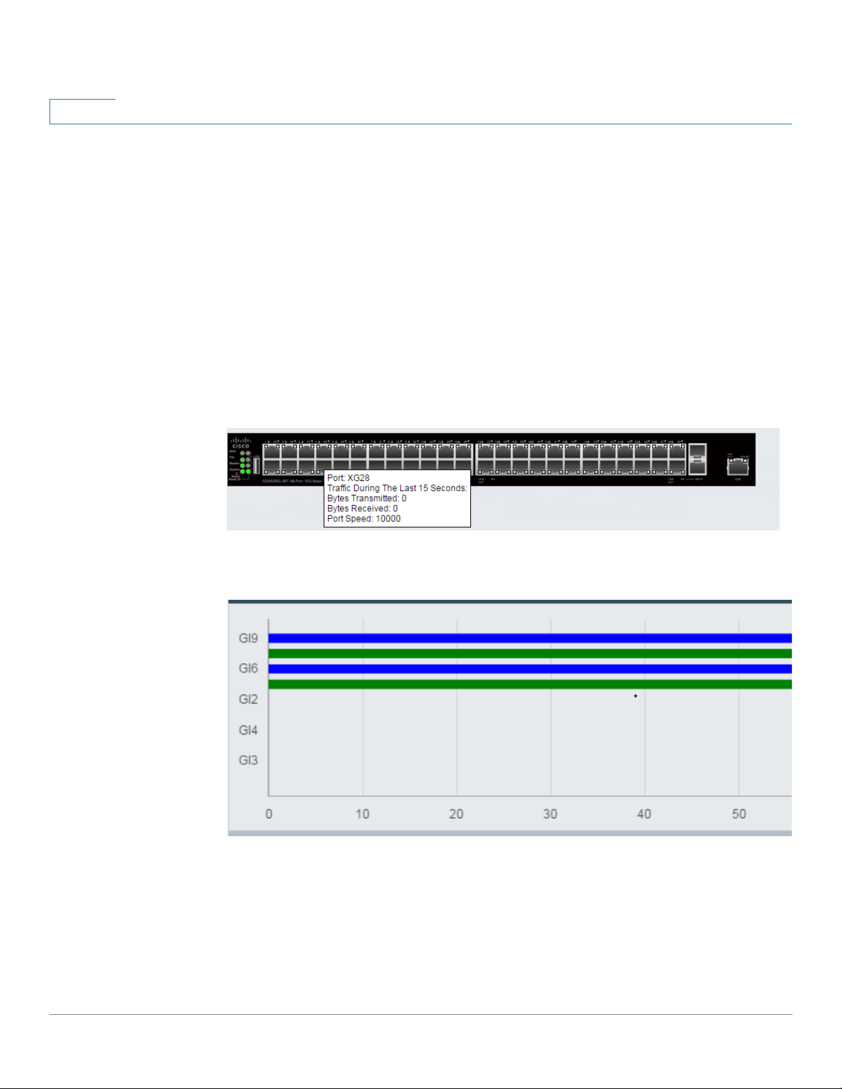
This modules displays the ports on the device in either device or chart view. The view is
selected in the configuration options (pencil icon in upper-right corner).
• Display Mode—Device View
Displays the device. Hovering over a port displays information about it.
• Display Mode—Chart View
A list of ports is displayed. The port utilization is displayed in bar format:
For each port, the following port utilization information is displayed:
Tx—% (green)
Rx—% (blue)
25 Cisco Sx250 Series Managed Switches, Firmware Release 2.2.5.x
Dashboard
PoE Utilization
PoE Utilization
2
• Refresh Time—Select one of the displayed options.
• Interface Statistics—Lick to link to the Status and Statistics -> Interface page.
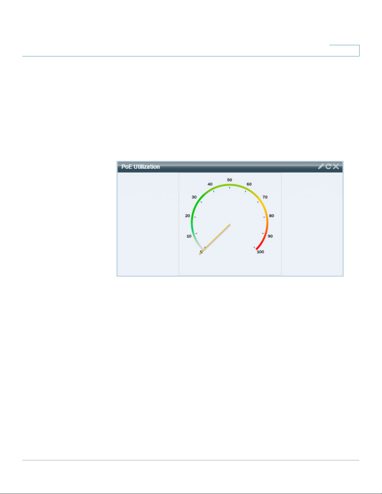
This module displays a graphic representation of the PoE utilization status., as shown below:
For a standalone unit, this module displays a gauge with a dial of values from 0-100. The
section of the dial from the traps threshold to 100 is red. In the middle of the gauge, the actual
PoE utilization value is shown in watts.
Each bar represents the PoE utilization percentage value of the device on a scale of 0 to 100. If
the PoE utilization is higher than the traps threshold, the bar is red. Otherwise the bar is green.
When hovering on a bar, a tooltip appears showing the actual PoE utilization of the unit in
watts.
Cisco Sx250 Series Managed Switches, Firmware Release 2.2.5.x 26
2
Latest Logs
Dashboard
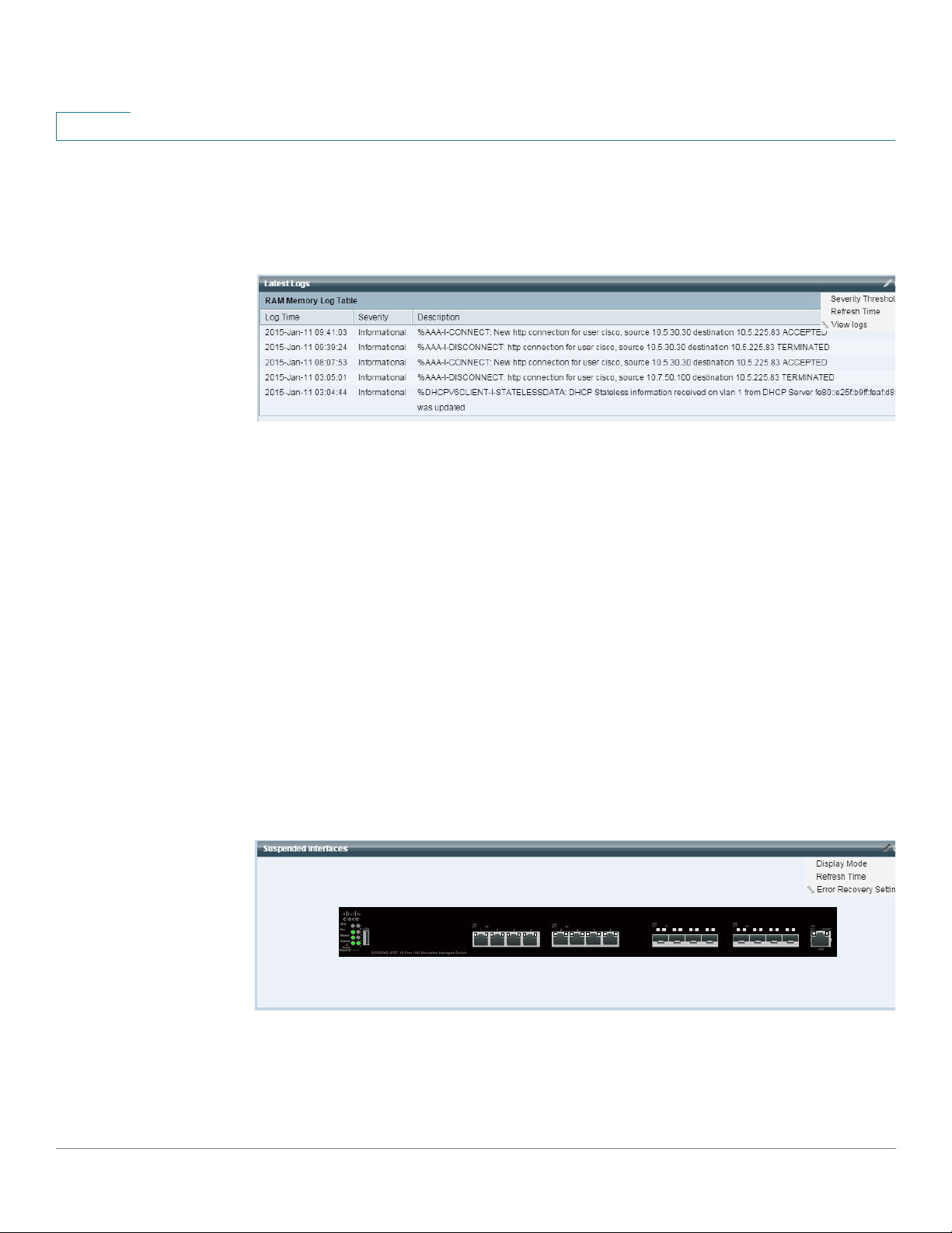
Latest Logs
This module contains information about the five latest events logged by the system as
SYSLOGs, as shown below:
The following configuration options (right-hand corner) are available:
• Severity Threshold—Described in Log Settings.
• Refresh Time—Select one of the options displayed.
• View Logs—Click to open RAM Memory.
NOTE See View Logs for more information.
Suspended Interfaces
This module displays interfaces that have been suspended in either device or table view. The
view is selected in the configuration options (pencil icon in upper-right corner).
• Device View
In this view, the device is displayed This is shown below:
All suspended ports in the device are shown as red.
Hovering over a suspended port displays a tooltip with the following information:
- Port name.
27 Cisco Sx250 Series Managed Switches, Firmware Release 2.2.5.x
Dashboard
Traffic Errors
2
- If the port is a member of a LAG, the LAG identity of the port.
- The suspension reason if it is suspended.
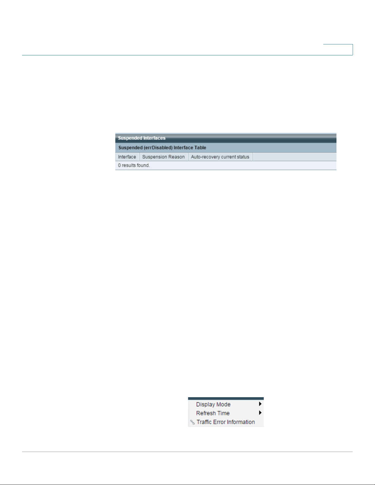
• Table V iew
Information is displayed in table form, as shown below:
The following fields are displayed:
- Interface—Port or LAG that was suspended
Traffic Errors
- Suspension Reason—Reason interface was suspended
- Auto-recovery current status—Has auto recovery been enable for the feature that
caused the suspension.
The following configuration options (right-hand corner) are available:
• Display Mode—Select either Device View or Table View.
• Refresh Time—Select one of the options displayed.
• Error Recovery Settings—Click to open Error Recovery Settings.
• Refresh Time—Select one of the options displayed.
This modules displays the number of error packets of various types that are counted on the
RMON statistics. The view is selected in the configuration options (pencil icon in upper-right
corner).
The following can be selected in from the pencil icon:
Cisco Sx250 Series Managed Switches, Firmware Release 2.2.5.x 28
2
Dashboard
Traffic Errors
• Display Mode - Device View
The device module mode displays a diagram of the device, as shown below:
All suspended ports in the device are shown as red.
Hovering over a suspended port displays a tooltip with the following information:
- Port name.
- If the port is a member of a LAG, the LAG identity of the port.
- Details of the last error logged on the port.
• Display Mode - Table View
- Interface—Name of port
- Last traffic error—Traffic error that occurred on a port and the last time the error
occurred.
• Refresh Time—Select one of the refresh rates.
• Traffic Error Information—Click to link to the Statistics page.
29 Cisco Sx250 Series Managed Switches, Firmware Release 2.2.5.x
Loading...