


 Loading...
390487
ADMINISTRATION
GUIDE
Cisco SPA232D Mobility Enhanced Phone Adapter
|
Contents |
|
|
|
|
Chapter 1: Getting Started |
5 |
Feature Overview |
5 |
Understanding Voice Service Operations |
6 |
ATA Voice Features |
6 |
Before You Begin |
12 |
Product Features |
12 |
Connecting the Equipment |
15 |
Configuration and Management of the ATA |
16 |
Registering a Cisco SPA302D Handset |
17 |
Additional Information |
18 |
Using the IVR for Administration |
18 |
Mounting the ATA |
22 |
Elements of the User Interface |
24 |
Chapter 2: Quick Setup for Voice over IP Service |
26 |
Chapter 3: Configuring the Network |
29 |
Basic Setup |
29 |
Network Service |
29 |
Internet Settings |
31 |
Network Settings for the LAN and DHCP Server |
34 |
Time Settings |
37 |
Advanced Settings |
39 |
Port Setting |
39 |
MAC Address Clone |
40 |
VPN Passthrough |
41 |
VLAN |
42 |
CDP & LLDP |
43 |
Application |
44 |
Quality of Service (QoS) |
44 |
Port Forwarding |
45 |
|
|
Cisco SPA232D Administrator Guide |
1 |
|
Contents |
|
|
|
|
Manually Adding Port Forwarding |
46 |
DMZ |
48 |
Chapter 4: Configuring the Voice Settings |
49 |
Information |
50 |
System |
60 |
SIP |
64 |
Provisioning |
74 |
Regional |
80 |
Line 1 Settings (PHONE Port) |
100 |
Configuration Tables |
117 |
PSTN (LINE Port) |
125 |
User 1 |
147 |
PSTN User |
152 |
DECT Line 1 - DECT Line 10 |
154 |
DECT User |
174 |
SSL/TLS Certificate |
177 |
Server Certification |
177 |
Client Certification |
178 |
Chapter 5: Administration Settings |
179 |
Management |
179 |
Web Access Management |
180 |
TR-069 |
182 |
SNMP |
184 |
User List (Password Management) |
186 |
Bonjour |
187 |
Reset Button |
187 |
Logging |
187 |
Log Module |
188 |
Log Setting |
190 |
|
|
Cisco SPA232D Administrator Guide |
2 |
|
Contents |
|
|
|
|
Log Viewer |
192 |
Diagnostics |
193 |
Ping Test |
193 |
Traceroute Test |
193 |
Factory Defaults |
194 |
Firmware Upgrade |
194 |
Configuration Management |
195 |
Backup Configuration |
195 |
Restore Configuration |
195 |
Reboot |
196 |
Chapter 6: Viewing the Status and Statistics |
197 |
System Information |
197 |
Interface Information |
198 |
Internet Status |
199 |
Port Statistics |
200 |
Memory Information |
201 |
DHCP Server Information |
202 |
Optimizing Fax Completion Rates |
212 |
VoIP-to-PSTN and PSTN-to-VoIP Calling |
215 |
How VoIP-To-PSTN Calls Work |
215 |
How PSTN-To-VoIP Calls Work |
217 |
Terminating Gateway Calls |
218 |
VoIP Outbound Call Routing |
218 |
Configuring VoIP Failover to PSTN |
220 |
Sharing One VoIP Account Between the PHONE and LINE Ports |
220 |
PSTN Call to Ring Line 1 |
221 |
Symmetric RTP |
221 |
Call Progress Tones |
221 |
Call Scenarios |
222 |
PSTN to VoIP Call with and Without Ring-Thru |
222 |
|
|
Cisco SPA232D Administrator Guide |
3 |

|
Contents |
|
|
|
|
VoIP to PSTN Call With and Without Authentication |
223 |
Call Forwarding to PSTN Gateway |
224 |
Configuring Dial Plans |
225 |
Digit Sequences |
226 |
Acceptance and Transmission of the Dialed Digits |
230 |
Dial Plan Timer (Off-Hook Timer) |
231 |
Interdigit Long Timer (Incomplete Entry Timer) |
232 |
Interdigit Short Timer (Complete Entry Timer) |
233 |
Resetting the Control Timers |
234 |
Cisco SPA232D Administrator Guide |
4 |

1
Getting Started
Thank you for choosing the Cisco SPA232D Mobility Enhanced Analog Telephone Adapter (ATA). This chapter provides more information about the features of the product and provides instructions about connecting the equipment and getting started in the web-based configuration utility.
Feature Overview
With the Cisco SPA232D Mobility Enhanced ATA, you can provide your analog phone and Cisco SPA302D cordless handsets with access to analog and Internet phone services through a standard RJ-11 phone port and a built-in DECT base station. The ATA supports up to five Cisco SPA302D handsets. The ATA connects to the Internet through a broadband (DSL or cable) modem or router. The ATA can be used with an on-site call-control system or an Internet-based call-control system.
The ATA is an intelligent low-density Voice over IP (VoIP) gateway that enables carrier-class residential and business IP Telephony services delivered over broadband or high-speed Internet connections. An ATA maintains the state of each call it terminates and reacts appropriately to user input events (such as on/off hook or hook flash). The ATAs use the Session Initiation Protocol (SIP) open standard so there is little or no involvement by a “middle-man” server or media gateway controller. SIP allows inter-operation with all ITSPs that support SIP.
The system supports four simultaneous calls, including “active” calls and “on-hold” calls. A phone or DECT handset can handle one on-hold call and one active call simultaneously.
Cisco SPA232D Administration Guide |
5 |
Getting Started |
1 |
|
|
Feature Overview |
|
|
|
|
|
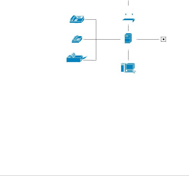
Understanding Voice Service Operations
The ATA allows calls to be made by using SIP-based Voice-over-IP (VoIP) services and traditional telephone Public Switched Telephone Network (PSTN) services. Calls can be placed and received by using an analog phone or fax machine and Cisco SPA302D handsets.
SPA232D typical topology
|
Internet Service Provider |
||||||
|
Internet (ADSL/Cable |
|
|||||
Analogue |
|
Modem) |
|
||||
|
|
|
|
|
|
|
|
|
|
|
|
|
|
|
|
|
|
|
|
|
|
|
|
Phone |
IP |
|
|
|
|
|
|
(FXS port) |
|
|
|
|
|||
|
|
|
|
|
WAN |
|
|
or |
|
|
|
|
|
|
|
|
|
|
|
|
|
|
|
Cordless |
FXS/DECT |
FXO |
|||||
Phone |
|
|
|
|
|
|
Active PSTN L |
(DECT) |
|
|
|
|
|
|
|
or |
Cisco SPA232D |
|
|||||
|
|
|
|
|
|
|
|
Fax Machine |
|
|
|
|
|
LAN |
|
(FXS port) |
|
|
|
|
|
|
|
|
|
|
|
|
|
|
|
|
|
|
|
|
|
|
|
|
|
|
|
|
|
|
|
|
|
|
|
PC |
|
||
The ATA maintains the state of each call and makes the proper reaction to user input events (such as on/off hook or hook flash). Because the ATA uses the Session Initiation Protocol (SIP), it is compatible with most Internet Telephony Service Provider (ITSP) offerings.
ATA Voice Features
The ATA can be custom provisioned within a wide range of configuration parameters. The following sections describe the factors that contribute to voice quality:
•Supported Codecs
•SIP Proxy Redundancy
•Other ATA Voice Features
Cisco SPA232D Administration Guide |
6 |

Getting Started |
1 |
|
|
Feature Overview |
|
|
|
|
|
Supported Codecs
The ATA supports the codecs listed below. You can use the default settings or configure the codec settings in the Audio Configuration section of these pages:
Line 1 Settings (PHONE Port), PSTN (LINE Port), and DECT Line 1 - DECT Line 10.
Codec |
Description |
|
|
G.711 (A-law and mu-law) |
Very low complexity codecs that support |
|
uncompressed 64 kbps digitized voice |
|
transmissions at one through ten 5 ms voice frames |
|
per packet. These codecs provide the highest |
|
narrow-band voice quality and uses the most |
|
bandwidth of any of the available codecs. |
|
|
G.726-32 |
Low complexity codec that supports compressed |
|
32 kbps digitized voice transmission at one through |
|
ten 10 ms voice frames per packet. This codec |
|
provides high voice quality. |
|
|
G.729a |
ITU G.729 voice coding algorithm used to |
|
compress digitized speech. G.729a is a reduced |
|
complexity version of G.729 requiring about half |
|
the processing power of G.729. The G.729 and |
|
G.729a bit streams are compatible and |
|
interoperable, but not identical. |
|
|
Cisco SPA232D Administration Guide |
7 |

Getting Started |
1 |
|
|
Feature Overview |
|
|
|
|
|
SIP Proxy Redundancy
In typical commercial IP Telephony deployments, all calls are established through a SIP proxy server. A typical SIP proxy server can handle thousands of subscribers. It is important that a backup server be available so that an active server can be temporarily switched out for maintenance. The ATA supports the use of backup SIP proxy servers (through DNS SRV) so that service disruption is minimized.
An easy way to support proxy redundancy is to configure your DNS server with a list of SIP proxy addresses. The ATA can be instructed to contact a SIP proxy server in a domain named in the SIP message. The ATA consults the DNS server to get a list of hosts in the given domain that provide SIP services. If an entry exists, the DNS server returns an SRV record that contains a list of SIP proxy servers for the domain, with their host names, priority, listening ports, and so on. The ATA tries to contact the list of hosts in the order of their stated priority.
If the ATA is currently using a lower priority proxy server, it periodically probes the higher priority proxy to see whether it is online, and switches back to the higher priority proxy when possible. You can use the default settings or configure the Proxy Redundancy Method in the Proxy and Registration section of the Line 1 Settings (PHONE Port) page and the DECT Line 1 - DECT Line 10 pages.
Other ATA Voice Features
•Silence Suppression and Comfort Noise Generation
Voice Activity Detection (VAD) with Silence Suppression is a means of increasing the number of calls supported by the network by reducing the average bandwidth required for a single call. VAD distinguishes between speech and non-speech signals, and Silence Suppression removes the natural silences that occur in a conversation. Therefore the IP bandwidth is used only to transmit speech. Comfort Noise Generation provides artificially-generated background white noise (sounds) to reassure callers that their calls are still connected during the silent periods. You can enable this feature in the Audio Configuration section of these pages: Line 1 Settings (PHONE Port), PSTN (LINE Port), and DECT Line 1 - DECT Line 10.
•Modem and Fax Pass-Through
-Modem pass-through mode can be triggered by predialing the Vertical Service Activation Code for the Modem Line Toggle Code. You can configure this setting in the Vertical Service Activation Codes section of the Regional page.
Cisco SPA232D Administration Guide |
8 |

Getting Started |
1 |
|
|
Feature Overview |
|
|
|
|
|
-FAX pass-through mode is triggered by the detection of a CED/CNG tone or an NSE event.
-Echo canceller is automatically disabled for Modem passthrough mode.
-Echo canceller is disabled for FAX pass-through if the parameter FAX Disable ECAN (Line 1 or 2 tab) is set to “yes” for that line (in that case FAX pass-through is the same as Modem pass-through)
-Call waiting and silence suppression are automatically disabled for both FAX and Modem pass-through. In addition, out-of-band DTMF transmission is disabled during modem or fax passthrough.
NOTE For more information, please refer to Audio Configuration, page 113 and
Configuration Tables, page 117.
•Adaptive Jitter Buffer
The ATA can buffer incoming voice packets to minimize the impact of variable network delays. This process is known as jitter buffering. The size of the jitter buffer adjusts to changing network conditions. The ATA has a Network Jitter Level control setting for each line of service. The jitter level determines how aggressively the ATA tries to shrink the jitter buffer over time to achieve a lower overall delay. If the jitter level is higher, it shrinks more gradually. If jitter level is lower, it shrinks more quickly. You can use the default settings or configure this feature in the Network Settings section of these pages: Line 1 Settings (PHONE Port), PSTN (LINE Port), and DECT Line 1 - DECT Line 10.
•Adjustable Audio Frames Per Packet
This feature allows the user to set the number of audio frames contained in one RTP packet. Packets can be adjusted to contain from 1–10 audio frames. Increasing the number of packets decreases the bandwidth utilized, but it also increases delay and may affect voice quality. You can configure this setting in the RTP Parameters section of the SIP page.
•DTMF Relay
The ATA may relay DTMF digits as out-of-band events to preserve the fidelity of the digits. This can enhance the reliability of DTMF transmission required by many IVR applications such as dial-up banking and airline information. You can configure this setting in the RTP Parameters section of the SIP page.
•Call Progress Tones
The ATA has configurable call progress tones. Call progress tones are generated locally on the ATA so that an end user is advised of status (such as ringback) Parameters for each type of tone (for instance a dial tone
Cisco SPA232D Administration Guide |
9 |
Getting Started |
1 |
|
|
Feature Overview |
|
|
|
|
|
played back to an end user) may include frequency and amplitude of each component, and cadence information. You can keep the default settings or configure these tones in the Call Progress Tones section of the Regional page.
•Call Progress Tone Pass Through
This feature allows the user to hear the call progress tones (such as ringing) that are generated from the far-end network.
•Echo Cancellation
Impedance mismatch between the telephone and the IP Telephony gateway phone port can lead to near-end echo. The ATA has a near-end echo canceller that compensates for impedance mismatch. The ATA also implements an echo suppressor with Comfort Noise Generator (CNG) so that any residual echo is not noticeable. This feature is enabled by default. You can configure this setting in the Audio Configuration of these pages:
Line 1 Settings (PHONE Port), PSTN (LINE Port), and DECT Line 1 - DECT Line 10.
•Hook Flash Events
The ATA can signal hook flash events to the proxy during a connected call. This feature can be used to provide advanced mid-call services with third- party-call control.
-Depending on the features that the service provider offers using third- party-call-control, you may need to disable Call Waiting Service, Three Way Conference Service, or Three Way Call Service to correctly signal a hook flash event to the softswitch. You can configure these settings in the Supplementary Service Subscription section of the Line 1 Settings (PHONE Port) page and the DECT Line 1 - DECT Line 10 pages.
-You can configure the length of time allowed for detection of a hook flash by adjusting the Hook Flash Timer parameter in the Control Timer Values section of the SIP page.
•Configurable Dial Plan with Interdigit Timers
The ATA has three configurable interdigit timers: an initial timeout signaling that a phone is taken off hook, a long timeout signaling the end of a dialed string, and a short timeout, signaling that more digits are expected. For more information, see Configuring Dial Plans, page 225.
•Polarity Control
The ATA allows the polarity to be set when a call is connected and when a call is disconnected. This feature is required to support some pay phone system and answering machines. You can configure these settings in the
Cisco SPA232D Administration Guide |
10 |

Getting Started |
1 |
|
|
Feature Overview |
|
|
|
|
|
FXS Port Polarity Configuration section of the Line 1 Settings (PHONE
Port) page.
•Calling Party Control
Calling Party Control (CPC) signals to the called party equipment that the calling party has hung up during a connected call by momentarily removing the voltage between the tip and the ring. This feature is useful for auto-answer equipment. You can configure these settings in the Control Timer Values section of the Regional page.
•Event Logging
You can enable logging and select the relative priority of events to be logged. The information can be sent to a Syslog Server. You can configure the syslog and debug settings in the Miscellaneous Settings section of the
System page.
•Encryption of SIP messages using SIP over TLS
You can enable SIP over Transport Layer Security (TLS) to encrypt the SIP messages between the service provider and the your business. SIP over TLS relies on the widely-deployed and standardized TLS protocol to encrypt the signaling messages. You can configure the SIP Transport parameter in the SIP Settings section of these pages: Line 1 Settings (PHONE Port), PSTN (LINE Port), and DECT Line 1 - DECT Line 10.
•Secure Calling using SRTP
Voice packets are encrypted by using Secure Real-Time Transport Protocol (SRTP). This function is implemented on a standards basis (RFC4568). Secure call service (Secure Call Serv) is enabled by default in the
Supplementary Service Subscription section of these pages: Line 1 Settings (PHONE Port) and DECT Line 1 - DECT Line 10. When this service is enabled, users can activate secure calling by pressing the star (*) key before dialing a phone number. Alternatively, you can enable the Secure Call Setting to encrypt all calls from a user’s phone or a DECT line. See the
Supplementary Service Settings section of the User 1 page and the DECT Line 1 - DECT Line 10 page.
Cisco SPA232D Administration Guide |
11 |

Getting Started |
1 |
|
|
Before You Begin |
|
|
|
|
|
Before You Begin
Before you begin the installation, make sure that you have the following equipment and services:
•An active Internet account and Voice over IP account
•Ethernet cable to connect to your broadband network device
•Phone to connect to your ATA
•Phone cable to connect your phone
•Optional: Uninterruptible Power Supply (UPS) to provide backup power
•Optional: Cisco SPA302D Mobility Enhanced Cordless Handsets
Product Features
Top Panel |
|
|
|
Feature |
Description |
|
Steady green—One or more handsets is |
|
registered. |
|
Fast flashing green—The base is in registration |
Page/ |
mode. To activate registration mode, press the |
Registration |
button for at least 7 seconds. |
|
Slow flashing green—The base is in paging mode |
|
or a handset is off hook. To activate paging mode to |
|
locate a handset, press the button for a few |
|
seconds; handsets ring. |
|
Off—No handset is registered to the base. |
|
|
|
Steady green—The line is off hook and connected |
|
to the local telephone system. |
|
Slow flashing green—The line is off hook. |
LINE |
Off—The port is not ready. |
|
|
|
|
|
Steady green—The device is on hook and |
|
registered to a SIP proxy. |
PHONE |
Slow flashing green—The device is off hook. |
Off—The port is not ready. |
|
|
|
|
Flashing green—Transmitting or receiving data |
|
through the WAN port. |
INTERNET |
Off—No link. |
|
|
|
|
Cisco SPA232D Administration Guide |
12 |
Getting Started |
1 |
|
|
Product Features |
|
|
|
|
|
Feature Description
Steady green—The system is ready.
Slow flashing green—Acquiring an IP address, if applicable. (DHCP is used by default.)
SYSTEM Fast flashing green—Upgrading the firmware.
Off—There is no power or the system cannot boot up.
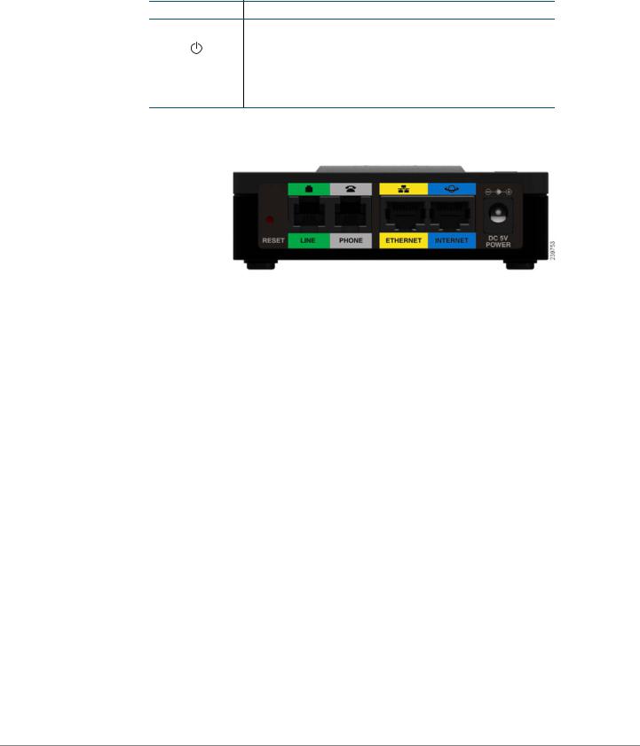
Back Panel
Feature |
Description |
|
|
RESET |
Performs two functions: |
|
Restart the ATA: Press quickly (less than a second) |
|
with a paperclip or similar object. |
|
Restore the factory default settings: Press and |
|
hold for 5 to 6 seconds. |
|
|
LINE (Green) |
Connects to an analog phone line, using an RJ- |
|
11 phone cable. |
|
|
PHONE (Gray) |
Connects to an analog phone, using an RJ-11 phone |
|
cable. |
|
|
ETHERNET |
Connects to a device on your local area network |
(Yellow) |
(LAN), such as a computer by using an Ethernet |
|
cable. |
|
|
INTERNET |
Connects to a broadband network device (DSL or |
(Blue) |
cable modem) or a network router by using an |
|
Ethernet cable. |
|
|
POWER |
Connects to a power by using the provided adapter. |
|
|
Cisco SPA232D Administration Guide |
13 |

Getting Started |
1 |
|
|
Product Features |
|
|
|
|
|
Default Settings |
|
|
|
Parameter |
Default Value |
|
|
Administrator Username |
admin |
|
|
Administrator Password |
admin |
|
|
User Username |
cisco |
|
|
User Password |
cisco |
|
|
Internet Connection Type |
Automatic Configuration - DHCP |
|
|
LAN IP Address |
192.168.15.1 |
(Also the address for the web- |
|
based configuration utility.) |
|
|
|
DHCP Range |
192.168.15.100-149 |
(DHCP server enabled by |
|
default.) |
|
|
|
Netmask |
255.255.255.0 |
|
|
PIN for handset registration, IP |
Blank |
settings, and SIP settings |
|
|
|
Cisco SPA232D Administration Guide |
14 |

Getting Started |
1 |
|
|
Connecting the Equipment |
|
|
|
|
|
Connecting the Equipment
NOTE For wall-mounting instructions, see Additional Information, page 18.
STEP 1 Connect the provided Ethernet cable to the INTERNET (Blue) port. Connect the other end of the cable directly to your broadband network device.
STEP 2 Connect the provided phone cable to the PHONE 1 (Gray) port. Connect the other end of the cable to your analog phone or fax machine.
STEP 3 Optionally, connect an Ethernet network cable to the ETHERNET (Yellow) port of the ATA. Connect the other end of the cable to a device on your network, such as a computer.
STEP 4 Connect an analog phone line to the LINE (Green) port to connect the ATA to your local telephone system.
STEP 5 Connect the provided power adapter to the POWER port. The unit powers on.
239756
WAN |
Cisco SPA232D Administration Guide |
15 |

Getting Started |
1 |
|
|
Configuration and Management of the ATA |
|
|
|
|
|
Configuration and Management of the ATA
You can use the web-based configuration utility to set up your ATA. You also can use the built-in Interactive Voice Response (IVR) system. (See Using the IVR for Administration, page 18.)
STEP 1 Connect the provided Ethernet network cable to the ETHERNET (Yellow) port of the ATA. Connect the other end of the cable to the Ethernet port of your PC.
STEP 2 Power on your computer.
NOTE: Make sure your computer’s Ethernet adapter is set to obtain an IP address automatically (DHCP). For more information, refer to the Help for your operating system.
STEP 3 Start a web browser on your computer.
STEP 4 In the Address bar, enter: 192.168.15.1
Note: 192.168.15.1 is the default local IP address of the ATA.
STEP 5 To log in for the first time, enter the default username, admin, and the default password, admin. The password is case sensitive.
NOTE: A user account allows access to limited settings and status pages. To log in as a user, enter cisco as the username and the password.
STEP 6 Use the Quick Setup page as needed to register your VoIP accounts in the fields for Line 1 and DECT Line1.
Your VoIP service may require only a few basic parameters to successfully register the Cisco SPA232D. The Quick Setup page offers a shortcut to enter the basic parameters. For a more comprehensive listing of parameters, choose the Voice menu, and then use the links in the navigation tree.
•Enter Proxy: Enter the domain name or URL of the service provider’s proxy server.
•Display Name: Enter the name of the business. This name typically is used for the Caller ID.
•User ID: Enter the user ID for your Internet account with this service provider.
•Password: Enter the password for your Internet account.
•Dial Plan (Line 1 only): Keep the default settings (recommended). Detailed information about the dial plan settings is available in the online Help and the administration guide.
Cisco SPA232D Administration Guide |
16 |
Getting Started |
1 |
|
|
Registering a Cisco SPA302D Handset |
|
|
|
|
|
Note: The Cisco SPA232D assigns DECT Line1 as the default line for outgoing calls from Cisco SPA302D handsets. If needed, you can configure additional VoIP accounts as separate “DECT Lines.” To do so, choose the Voice menu, and then use the DECT Line 1~10 links in the navigation tree. Use the check boxes on the Quick Setup page to associate the DECT Line(s) to each handset.
STEP 7 Click Submit to save your settings.
STEP 8 If you wish to change the PIN for handset registration, open the Voice > System page, and then enter up to four digits in the Handset (HS) Pairing Password field. Click Submit to save your settings.
Registering a Cisco SPA302D Handset
You can register Cisco SPA302D handsets to the integrated DECT base station.
These handsets can be purchased separately.
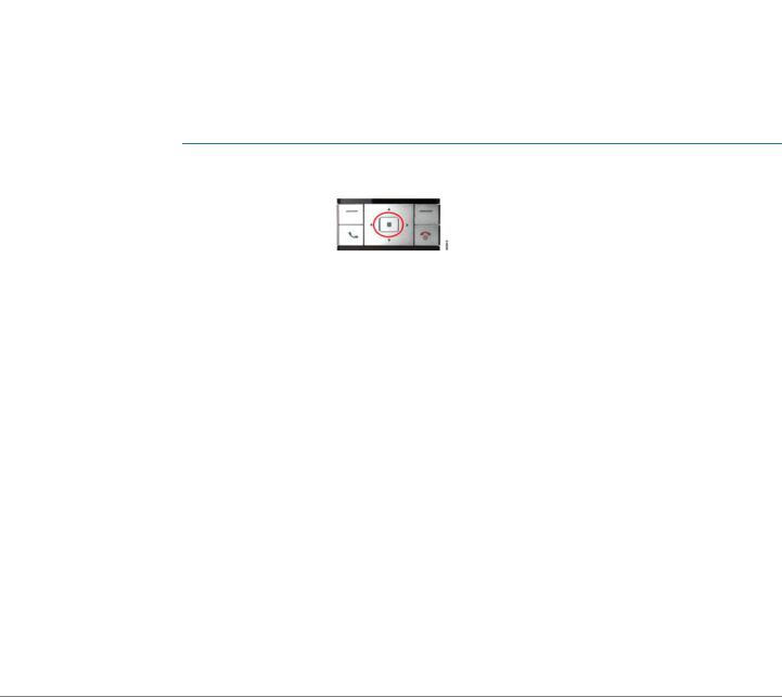
STEP 1 On the Cisco SPA302D handset, press the center Select button on the 4-way navigation keypad.
STEP 2 Select Register.
STEP 3 Using the navigation arrows, scroll to the Settings icon and press the center navigation button to select it.
STEP 4 Select Handset Registration.
STEP 5 On the Cisco SPA232D, press the Page/Registration button and hold it down for at least seven seconds until the green status light flashes quickly.
TIP: If you press the button for fewer than seven seconds, the green status light flashes slowly, indicating the unit is in “paging” mode and is not in registration mode. Registration will not work if the unit is in paging mode.
STEP 6 The default PIN is blank, so do not enter a PIN. Press the left softkey to confirm that you want to register the handset. The “registering” message appears.
STEP 7 To verify that the handset registered to the base station, confirm that the wireless status icon is solid and that the handset ID, such as DECT1 or DECT 2, appears near the top right corner of the display screen.
Cisco SPA232D Administration Guide |
17 |

Getting Started |
1 |
|
|
Additional Information |
|
|
|
|
|
Additional Information
Using the IVR for Administration
An IVR system is available to help you to configure and manage your ATA. You can use the telephone keypad to select options and to make your entries.
To access the IVR menu:
STEP 1 Connect an analog phone to the PHONE port of the ATA.
STEP 2 Press the star key four times: ****
STEP 3 After the greeting plays, press the keys on the phone keypad to select your options.
STEP 4 Enter the code for the desired action. See the IVR Actions table for details.
TIPS:
•Enter the numbers slowly, listening for the audio confirmation before entering the next number.
•After you select an option, press the # (pound) key.
•To exit the menu, hang up the telephone or enter 3948# to exit.
•After entering a value, such as an IP address, press the # (pound) key to indicate that you have finished your selection. To save the new setting, press 1. To review the new setting, press 2. To re-enter the new setting, press 3. To cancel your entry and return to the main menu, press * (star).
•While entering a value, you can cancel the changes by pressing the * (star) key twice within half a second. Be sure to press the key quickly, or the * will be treated as a decimal point entry.
•If the menu is inactive for more than one minute, the ATA times out. You will need to re-enter the menu by pressing the star key four times: ****. Your settings take effect after you hang up the telephone or exit the IVR. The ATA may reboot at this time.
Cisco SPA232D Administration Guide |
18 |

Getting Started |
1 |
|
|
Additional Information |
|
|
|
|
|
•To enter the decimal points in an IP address, press the * (star) key. For example, to enter the IP address 191.168.1.105, perform the following tasks:
–Press these keys: 191*168*1*105.
–Press the # (pound) key to indicate that you have finished entering the IP address.
–Press 1 to save the IP address or press the * (star) key to cancel your entry and return to the main menu.
IVR Actions |
|
|
|
|
|
IVR Action |
Menu |
Choices and Instructions |
|
Option |
|
|
|
|
Enter IVR Menu |
**** |
|
|
|
|
Check Internet |
100 |
|
Connection Type |
|
|
|
|
|
Set Internet Connection |
101 |
DHCP: 0 |
Type |
|
Static IP: 1 |
|
|
|
|
|
PPPoE: Press 2 |
|
|
|
Check Internet IP |
110 |
|
Address (WAN port) |
|
|
|
|
|
Set Static IP Address |
111 |
Enter the IP address by |
(WAN) |
|
using numbers on the |
|
|
telephone key pad. Use the |
|
|
* (star) key when entering a |
|
|
decimal point. |
Note: This option is available only after you choose Static IP as the Internet Connection Type, through option 101.
Check Network Mask |
120 |
Cisco SPA232D Administration Guide |
19 |
Getting Started |
1 |
|
|
Additional Information |
|
|
|
|
|
|
|
|
IVR Action |
Menu |
Choices and Instructions |
|
Option |
|
|
|
|
Set Network Mask |
121 |
To enter the value, press |
|
|
numbers on the telephone |
|
|
key pad. Press the * (star) |
|
|
key to enter a decimal |
|
|
point. |
|
|
Note: This option is |
|
|
available only after you |
|
|
choose Static IP as the |
|
|
Internet Connection Type, |
|
|
through option 101. |
|
|
|
Check Gateway IP |
130 |
|
Address |
|
|
|
|
|
Set Gateway IP Address |
131 |
To enter the value, press |
|
|
numbers on the telephone |
|
|
key pad. Press the * (star) |
|
|
key to enter a decimal |
|
|
point. |
|
|
Note: This option is |
|
|
available only after you |
|
|
choose Static IP as the |
|
|
Internet Connection Type, |
|
|
through option 101. |
|
|
|
Check MAC Address |
140 |
|
|
|
|
Check Firmware Version |
150 |
|
|
|
|
Check Primary DNS |
160 |
|
Server Setting |
|
|
|
|
|
Set Primary DNS Server |
161 |
To enter the value, press |
|
|
numbers on the telephone |
|
|
key pad. Press the * (star) |
|
|
key to enter a decimal |
|
|
point. |
Note: This option is available only after you choose Static IP as the Internet Connection Type, through option 101.
|
|
Check Internet web |
170 |
server port |
|
Cisco SPA232D Administration Guide |
20 |

Getting Started |
1 |
|
|
Additional Information |
|
|
|
|
|
|
|
|
|
IVR Action |
Menu |
Choices and Instructions |
|
|
Option |
|
|
|
|
|
|
SPA122 only: Check LAN |
210 |
|
|
IP address (Ethernet port) |
|
|
|
|
|
|
|
Announce Line 1 SIP |
1910 |
|
|
Transport |
|
|
|
|
|
|
|
Set Line 1 SIP Transport |
1911 |
0: UDP |
|
|
|
1: TCP |
|
|
|
2: TLS |
|
|
|
|
|
Check Line 2 SIP |
1920 |
|
|
Transport |
|
|
|
|
|
|
|
Set Line 2 SIP Transport |
1921 |
0: UDP |
|
|
|
1: TCP |
|
|
|
2: TLS |
|
|
|
|
|
Exit IVR |
3948 |
|
|
|
|
|
|
Allow or prevent WAN |
7932 |
1: Enable |
|
access to the |
|
0: Disable |
|
administration web |
|
|
|
server |
|
|
|
The system will allow |
|
|
|
WAN access only if the |
|
|
|
default admin username |
|
|
|
and password have been |
|
|
|
changed in the |
|
|
|
Configuration Utility. |
|
|
|
|
|
|
|
Factory Reset of Unit |
73738 |
When prompted, press 1 to |
|
WARNING: All non- |
“RESET” |
confirm, or press * (star) to |
|
cancel. After you hear |
|||
default settings will be |
|
||
|
“Option successful,” hang |
||
lost. This includes |
|
||
|
up the phone. The ATA |
||
network and service |
|
||
|
reboots. |
||
provider data. |
|
||
|
|
||
|
|
|
|
Reboot of Voice System |
732668 |
After you hear “Option |
|
|
“REBOOT |
successful,” hang up the |
|
|
phone. The ATA reboots. |
||
|
” |
|
|
|
|
|
Cisco SPA232D Administration Guide |
21 |
Getting Started |
1 |
|
|
Additional Information |
|
|
|
|
|
Mounting the ATA
You can place the ATA on a desktop or mount it on a wall.
!
CAUTION To prevent the ATA from overheating, do not operate it in an area that exceeds an ambient temperature of 104°F (40°C).
Desktop Placement
Place the ATA on a flat surface near an electrical outlet.
WARNING Do not place anything on top of the ATA; excessive weight could damage it.
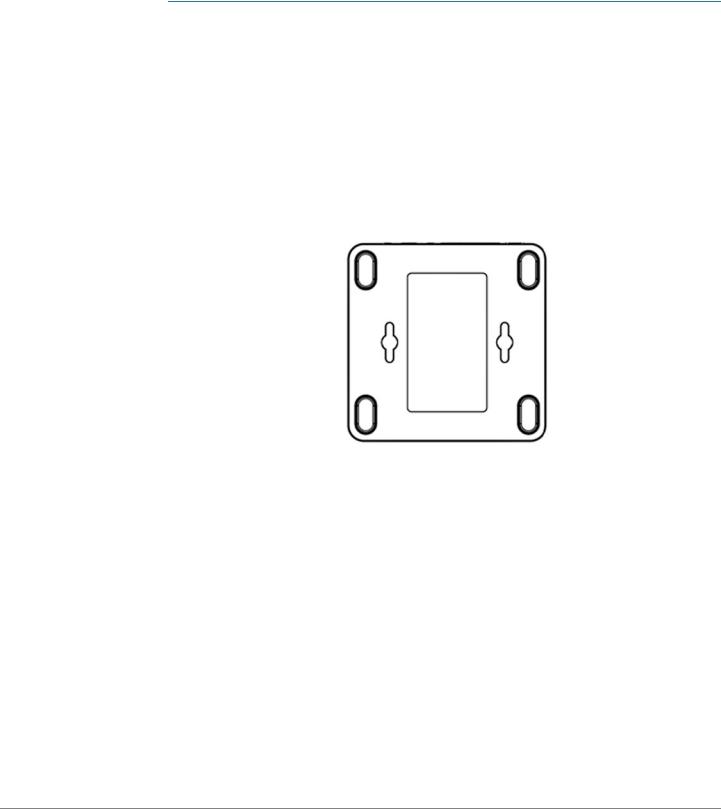
Wall Mounting
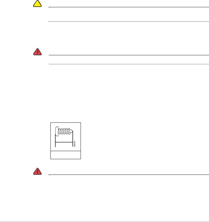
The ATA has two wall-mount slots on the bottom panel. To mount the ATA on a wall, you need mounting hardware (not included). Suggested hardware is illustrated (not true to scale).
Recommended hardware (not included): Two number-six pan-head tapping screws, 5/8-in. length, with anchors for sheet rock installation.
15,8 mm
WARNING |
Insecure mounting might damage the ATA or cause injury. Cisco is not responsible |
|
for damages incurred by insecure wall-mounting. |
|
|
Cisco SPA232D Administration Guide |
22 |
Getting Started |
1 |
|
|
Additional Information |
|
|
|
|
|
To mount the unit to the wall:
STEP 1 Determine where you want to mount the unit. Verify that the surface is smooth, flat, dry, and sturdy.
STEP 2 Drill two pilot holes into the surface 58 mm apart (about 2.28 in.). Make sure that the holes are at the same height above the floor so that the unit is level and secure in either of its two safety-certified orientations.
STEP 3 Insert a screw into each hole, leaving a gap of 5 mm (0.1968 in.) between the underside of each screw head and the surface of the wall.
STEP 4 Place the unit wall-mount slots over the screws and slide the unit down until the screws fit snugly into the wall-mount slots.
Cisco SPA232D Administration Guide |
23 |
Getting Started |
1 |
|
|
Elements of the User Interface |
|
|
|
|
|
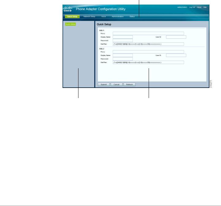
Elements of the User Interface
Before you use your ATA, become familiar with the following features of the user interface.
Screen Elements
1
2 |
3 |
Component |
Description |
|
|
1. Menu Bar |
Provides access to the modules of the |
(top) |
configuration utility. Click a menu to view the |
|
options in the navigation tree. |
|
|
2. Navigation |
Provides access to the configuration pages |
Tree |
within the selected module. Click a category |
(left panel) |
heading to view the list of features. Click a link |
|
to open the configuration page. |
|
|
3. Configuration |
Settings for the selected feature. |
Page |
|
(main area) |
|
|
|
Cisco SPA232D Administration Guide |
24 |

Getting Started |
1 |
|
|
Elements of the User Interface |
|
|
|
|
|
Configuration Utility Icons
Many configuration pages provide the following icons for common tasks.
Icon |
Description |
|
|
Edit Icon |
The Edit icon lets you edit an existing item from a list. |
|
After making your changes, click the Submit button to |
|
save your changes. |
|
|
Add Item Icon |
The Add Item icon lets you add an item to a list. After |
|
you have created a new item, click the Submit button to |
|
save the new item. |
|
|
Delete Item Icon |
The Delete Item icon lets you delete an item from a list. |
|
After you have deleted an item, click the Submit button |
|
to save your changes. |
|
|
Saving the Settings
Your settings on a configuration page are not saved until you click the Submit button. When you navigate to another page, any unsaved settings are abandoned. Changes cannot be saved while calls are in progress. Try again when the phones are idle.
To clear the settings without saving them, you can click the Cancel button.
Help
To view information about the configuration pages, click the Help link near the top right corner of the configuration utility. You can then use the table of contents to find topics of interest.
Logout
To exit the configuration utility, click the Logout link near the top right corner of the window. The Login page appears. You can close the browser window.
Cisco SPA232D Administration Guide |
25 |

2
Quick Setup for Voice over IP Service
The Quick Setup page is displayed automatically when you first log on ATA. You can use this page to quickly configure connectivity to your provider’s Voice over IP network for your analog phone and Cisco SPA302D handsets.
NOTE Connecting to your service provider’s network requires Internet connectivity. With the default network settings, your ATA should have Internet connectivity when you connect a cable from the WAN port of the ATA to a port on your router or broadband network device. For more information, see Internet Settings, page 31.
To open this page: Click Quick Setup in the menu bar.
STEP 1 Specify the settings for the phone service to be used by each type of device or line. Follow the requirements and recommendations of your service provider. The options are described below.
Device/line types:
•Line 1: The phone service used by an analog (FXS) phone or fax machine that is connected to the PHONE port.
•PSTN: The phone service used by a phone line that is connected from the LINE port to the PSTN.
•DECT Line 1: The phone service used by all connected Cisco SPA302D cordless handsets (when using the default settings in DECT Handset Outgoing Line Selection and DECT Line Contact List sections). You can add additional phone services for these handsets on the Voice > DECT Line 2 to
DECT Line 10 pages.
Settings:
•Proxy: Enter the domain name or URL of the service provider’s proxy server.
•Display Name: Enter the name that you want to use to identify your account. This name typically is used as your Caller ID name.
•User ID: Enter the user ID that is required to log in to your Internet account.
Cisco SPA232D Administration Guide |
26 |

Quick Setup for Voice over IP Service |
2 |
|
|
|
|
|
|
•Password: Enter the password that is required to log in to your Internet account.
•Dial Plan in (Line section only): Keep the default settings (recommended) or edit the dial plan to suit your site. For more information, see Configuring Dial Plans, page 225.
STEP 2 DECT Handset Outgoing Line Selection: For each DECT Handset, check the boxes to choose the DECT Lines for outgoing calls. Uncheck the boxes for the lines that you do not want to use.
•If you are using only one phone service for all Cisco SPA302D handsets, simply configure the DECT Line 1 settings above and keep the default settings in this section.
•If you have multiple lines, you can select multiple lines for each handset. Alternatively, check the All Lines box to make all lines. The enabled options will be listed on the phone screen when the user displays the call options or holds down the green call button.
•Choose a Default line, which will be selected automatically for a call when the user presses the green call button.
•Optionally, if you enabled multiple lines, enable Failover by selecting yes. When this feature is enabled and a call fails through the selected line, the ATA automatically attempts to place the call over another enabled DECT line.
NOTE Cisco SPA232D now supports PSTN to DECT and DECT to PSTN outgoing line failover.
STEP 3 DECT Line Contact List: For each line, check the boxes to choose the handsets that ring when an incoming call is received. Uncheck the boxes for the handsets that you do not want to ring. Check the All Handsets box to ring all handsets for the specified line.
STEP 4 Click Submit to save your settings. The voice service will restart.
STEP 5 To verify your progress, perform the following tasks:
a.Click Voice in the menu bar, and then click Info in the navigation tree. Verify that the Registration State is Registered for all configured lines (Line 1 Status, PSTN Line Status, and DECT 1 Status ~ DECT 10 Status).
If the line is not registered, you may need to refresh the browser several times because it can take a few seconds for the registration to complete. Also verify that your Internet Settings, including DNS server settings, are configured according to the information from your ISP. For more information, see Internet Settings, page 31.
Cisco SPA232D Administration Guide |
27 |

Quick Setup for Voice over IP Service |
2 |
|
|
|
|
|
|
b.Use an external phone to place an inbound call to the telephone number that was assigned by your ITSP. Verify that the phone rings and you have two-way audio on the call.
Cisco SPA232D Administration Guide |
28 |

3
Configuring the Network
This chapter describes how to configure the network settings for your ATA. It includes the following sections:
•Basic Setup
•Advanced Settings
•Application
Basic Setup
Use the Network Setup > Basic Setup pages to configure your Internet connection, local network settings, and your time settings.
•Network Service
•Internet Settings
•Network Settings for the LAN and DHCP Server
•Time Settings
Network Service
Use the Network Setup > Basic Setup > Network Service page to configure the operating mode of the ATA.
To open this page: Click Network Setup in the menu bar, and then click Basic Setup > Network Service in the navigation tree. After making changes, click Submit to save your settings, or click Cancel to redisplay the page with the saved settings.
Cisco SPA232D Administration Guide |
29 |
Loading...