


 Loading...
Cisco SCE 2000 4/8xFE
Installation and Configuration Guide
Version 3.0.5
OL-7826-05
Corporate Headquarters
Cisco Systems, Inc. 170 West Tasman Drive
San Jose, CA 95134-1706 USA
http://www.cisco.com Tel: 408 526-4000
800 553-NETS (6387) Fax: 408 526-4100
Customer Order Number: DOC-782605=
Text Part Number: OL-7826-05
THE SPECIFICATIONS AND INFORMATION REGARDING THE PRODUCTS IN THIS MANUAL ARE SUBJECT TO CHANGE WITHOUT NOTICE. ALL STATEMENTS, INFORMATION, AND RECOMMENDATIONS IN THIS MANUAL ARE BELIEVED TO BE ACCURATE BUT ARE PRESENTED WITHOUT WARRANTY OF ANY KIND, EXPRESS OR IMPLIED. USERS MUST TAKE FULL RESPONSIBILITY FOR THEIR APPLICATION OF ANY PRODUCTS.
THE SOFTWARE LICENSE AND LIMITED WARRANTY FOR THE ACCOMPANYING PRODUCT ARE SET FORTH IN THE INFORMATION PACKET THAT SHIPPED WITH THE PRODUCT AND ARE INCORPORATED HEREIN BY THIS REFERENCE. IF YOU ARE UNABLE TO LOCATE THE SOFTWARE LICENSE OR LIMITED WARRANTY, CONTACT YOUR CISCO REPRESENTATIVE FOR A COPY.
The following information is for FCC compliance of Class A devices: This equipment has been tested and found to comply with the limits for a Class A digital device, pursuant to part 15 of the FCC rules. These limits are designed to provide reasonable protection against harmful interference when the equipment is operated in a commercial environment. This equipment generates, uses, and can radiate radio-frequency energy and, if not installed and used in accordance with the instruction manual, may cause harmful interference to radio communications. Operation of this equipment in a residential area is likely to cause harmful interference, in which case users will be required to correct the interference at their own expense.-
The following information is for FCC compliance of Class B devices: The equipment described in this manual generates and may radiate radio-frequency energy. If it is not installed in accordance with Cisco’s installation instructions, it may cause interference with radio and television reception. This equipment has been tested and found to comply with the limits for a Class B digital device in accordance with the specifications in part 15 of the FCC rules. These specifications are designed to provide reasonable protection against such interference in a residential installation. However, there is no guarantee that interference will not occur in a particular installation.
Modifying the equipment without Cisco’s written authorization may result in the equipment no longer complying with FCC requirements for Class A or Class B digital devices. In that event, your right to use the equipment may be limited by FCC regulations, and you may be required to correct any interference to radio or television communications at your own expense.
You can determine whether your equipment is causing interference by turning it off. If the interference stops, it was probably caused by the Cisco equipment or one of its peripheral devices. If the equipment causes interference to radio or television reception, try to correct the interference by using one or more of the following measures:
•Turn the television or radio antenna until the interference stops.
•Move the equipment to one side or the other of the television or radio.
•Move the equipment farther away from the television or radio.
•Plug the equipment into an outlet that is on a different circuit from the television or radio. (That is, make certain the equipment and the television or radio are on circuits controlled by different circuit breakers or fuses.)
Modifications to this product not authorized by Cisco Systems, Inc. could void the FCC approval and negate your authority to operate the product.
The Cisco implementation of TCP header compression is an adaptation of a program developed by the University of California, Berkeley (UCB) as part of UCB’s public domain version of the UNIX operating system. All rights reserved. Copyright © 1981, Regents of the University of California.
NOTWITHSTANDING ANY OTHER WARRANTY HEREIN, ALL DOCUMENT FILES AND SOFTWARE OF THESE SUPPLIERS ARE PROVIDED “AS IS” WITH ALL FAULTS. CISCO AND THE ABOVE-NAMED SUPPLIERS DISCLAIM ALL WARRANTIES, EXPRESSED OR IMPLIED, INCLUDING, WITHOUT LIMITATION, THOSE OF MERCHANTABILITY, FITNESS FOR A PARTICULAR PURPOSE AND NONINFRINGEMENT OR ARISING FROM A COURSE OF DEALING, USAGE, OR TRADE PRACTICE.
IN NO EVENT SHALL CISCO OR ITS SUPPLIERS BE LIABLE FOR ANY INDIRECT, SPECIAL, CONSEQUENTIAL, OR INCIDENTAL DAMAGES, INCLUDING, WITHOUT LIMITATION, LOST PROFITS OR LOSS OR DAMAGE TO DATA ARISING OUT OF THE USE OR INABILTY TO USE THIS MANUAL, EVEN IF CISCO OR ITS SUPPLIERS HAVE BEEN ADVISED OF THE POSSIBILITY OF SUCH DAMAGES.
CCSP, the Cisco logo, and the Cisco Square Bridge logo are trademarks of Cisco Systems, Inc; Changing the Way We Work, Live, Play, and Learn is a service mark of Cisco Systems, Inc.; and Access Registrar, Aironet, ASIST, BPX, Catalyst, CCDA, CCDP, CCIE, CCIP, CCNA, CCNP, CCSP, Cisco, the Cisco Certified Internetwork Expert logo, Cisco IOS, Cisco Press, Cisco Systems, Cisco Systems Capital, the Cisco Systems logo, Cisco Unity, Enterprise/Solver, EtherChannel, EtherFast, EtherSwitch, Fast Step, Follow Me Browsing, FormShare, GigaDrive, GigaStack, HomeLink, Internet Quotient, IOS, IP/TV, iQ Expertise, the iQ logo, iQ Net Readiness Scorecard, iQuick Study, LightStream, Linksys, MeetingPlace, MGX, Networking Academy, Network Registrar, Packet, PIX, ProConnect, RateMUX, ScriptShare, SlideCast, SMARTnet, StackWise, The Fastest Way to Increase Your Internet Quotient, and TransPath are registered trademarks of Cisco Systems, Inc. and/or its affiliates in the United States and certain other countries.
All other trademarks mentioned in this document are the property of their respective owners. The use of the word partner does not imply a partnership relationship between Cisco and any other company. (0609R)
Printed in the USA on recycled paper containing 10% postconsumer waste.
Cisco SCE 2000 Installation and Configuration Guide
Copyright © 2002-2006 Cisco Systems, Inc.
All rights reserved.

C O N T E N T S
Preface v
Document Revision History v
Audience vi
Organization vi
Related Publications vii
Conventions viii
Obtaining Documentation ix
World Wide Web ix
Documentation CD-ROM ix
Ordering Documentation ix
Documentation Feedback x
Obtaining Technical Assistance x
Cisco.com x
Technical Assistance Center x
General Overview 1-1
The Cisco Service Control Concept 1-1
Service Control for Broadband Service Providers 1-2
Cisco Service Control Capabilities 1-2
The SCE Platform 1-3
Management and Collection 1-4
Network Management 1-5
Subscriber Management 1-5
Service Configuration Management 1-5
Data Collection 1-6
Introduction to the SCE Platform 2-1
The SCE Platform 2-1
Front Panel 2-1
Cisco SCE 2000 4/8xFE Installation and Configuration Guide
|
OL-7826-05 |
i |
|
|
|

Contents
Back Panel 2-4
Checking the Shipping Container Contents 2-5
SCE 2000 Installation Checklist 2-6
Topology 3-1
The SCE 2000 Platform 3-1
Topology Considerations 3-1
Functionality 3-2
Number of links 3-2
Redundancy 3-2
Link Continuity 3-3
Physical Topologies 3-4
Single SCE 2000 Topologies 3-4
Two Cascaded SCE 2000s For Dual Links 3-7
Topology-Related Parameters 3-8
Installation and Maintenance 4-1
Preparing to Install the SCE 2000 Platform 4-1 Tools and Parts Required 4-2
Site Requirement Guidelines 4-3 Installing the SCE 2000 Platform 4-4
Installation Precautions 4-5
Installing the SCE 2000 on a Workbench or Tabletop 4-5 Rack-Mounting a SCE 2000 Platform 4-6
Attaching a Chassis Ground Connection 4-10 Power Supply Overview 4-11
LEDs 4-12
Power Supply Specifications 4-14
Removing and Replacing a Power Supply Unit 4-14
Powering Down the Power Supply Unit and Disconnecting Input Power 4-15 Removing the Power Supply Unit 4-16
Replacing the Power Supply Unit 4-17 Reconnecting the Power 4-17
Fan Module Overview 4-20
Removing and Replacing the Fan Module 4-20
Cisco SCE 2000 4/8xFE Installation and Configuration Guide
ii |
OL-7826-05 |
|
|
|
|

Contents
Replacing the Battery 4-22
Connecting the Management Interfaces and Performing Initial System
Configuration 5-1
Connecting the Local Console 5-1
Setting Up the Local Console 5-2
Initial System Configuration 5-3
Setup Command Parameters 5-3
Step 1: Configuring Initial Settings 5-6
Step 2: Configuring the Hostname 5-7
Step 3: Setting the Passwords 5-7
Step 4: Configuring Time Settings 5-8
Step 5: Configuring the DNS Settings 5-10
Step 6: Configuring the RDR Formatter Destination 5-11
Step 7: Configuring Access Control Lists (ACLs) 5-12
Step 8: Configuring SNMP 5-16
Step 9: Configuring the Topology-Dependent Parameters 5-19
Step 10: Completing and Saving the Configuration 5-23
Connecting the Management Interface 5-25
Cabling the Management Port 5-26
Verifying Management Interface Connectivity 5-26
Cabling the Line Ports and Completing the Installation 6-1
Connecting the line ports to the network 6-1
Cabling Diagrams 6-2
Connecting the FE Line Interface Ports 6-6
Testing Connectivity: Examining Link LEDs and Counters 6-7
Installing a Cascaded System 6-9
CLI Commands for Cascaded Systems 6-10
Loading and Activating a Service Control Application 6-13
Basic SCE 2000 Platform Operations 7-1
Starting the SCE 2000 Platform 7-1
Checking Conditions Prior to System Startup 7-1
Starting the System and Observing Initial Conditions 7-2
Final Tests 7-3
Cisco SCE 2000 4/8xFE Installation and Configuration Guide
|
OL-7826-05 |
iii |
|
|
|

Contents
Managing SCE 2000 Configurations 7-4
Viewing Configuration 7-4
Saving the Configuration Settings 7-5
Recovering a Previous Configuration 7-6
Performing Complex Configurations 7-7
Displaying the SCE Platform Version Information 7-8
Displaying the SCE Platform Inventory 7-9
Displaying the System Uptime 7-10
Rebooting and Shutting Down the SCE Platform 7-10
Rebooting the SCE Platform 7-10
Shutting Down the SCE Platform 7-11
Troubleshooting 8-1
Troubleshooting Overview 8-1
Troubleshooting Tools 8-2
CLI Commands for Troubleshooting 8-2
The User Log 8-4
Check the LEDs 8-7
Problem Solving Using a Subsystems Approach 8-8
Identifying Startup Problems 8-8
Troubleshooting the Power Subsystem 8-9
Troubleshooting the Firmware Package Installation 8-10
Troubleshooting the Management Subsystem 8-11
Troubleshooting the Link Interface Subsystem 8-13
Index I-1
Cisco SCE 2000 4/8xFE Installation and Configuration Guide
iv |
OL-7826-05 |
|
|
|
|

Preface
This preface describes who should read the SCE 2000 4/8xFE Installation and Configuration Guide, how it is organized, and its document conventions.
Document Revision History
Cisco Service Control Release |
Part Number |
Publication Date |
|
|
|
Release 3.0.5 |
OL-7824-05 |
November, 2006 |
|
|
|
DESCRIPTION OF CHANGES
•Added requirement for dark fiber cabling between cascade ports.
•Added maximum hostname length.
Cisco Service Control Release |
Part Number |
|
Publication Date |
|
|
|
|
|
|
Release 3.0 |
OL-7826-04 |
|
February, 2006 |
|
|
|
|
|
|
DESCRIPTION OF CHANGES |
|
|
|
|
Updated circuit breaker information. |
|
|
|
|
|
|
|
|
|
Cisco Service Control Release |
Part Number |
|
Publication Date |
|
|
|
|
|
|
Release 3.0 |
OL-7826-03 |
|
December, 2005 |
|
|
|
|
|
|
DESCRIPTION OF CHANGES
Added the following new features:
• Redundant management (Mng) port
Cisco Service Control Release |
Part Number |
Publication Date |
|
|
|
Release 2.5.7 |
OL-7826-02 |
August, 2005 |
|
|
|
DESCRIPTION OF CHANGES
Complete reorganization and revision of product documentation.
Cisco SCE 2000 4/8xFE Installation and Configuration Guide
|
OL-7826-05 |
v |
|
|
|

Preface
Audience
Audience
This guide is for the networking or computer technician responsible for installing and configuring the SCE 2000 platform on-site. To use this publication, you should be familiar with telecommunications equipment and installation procedures, as well as electronic circuitry and wiring practices. You should also have experience as an electronic or electromechanical technician.
This installation guide explains the initial hardware installation and basic configuration procedures for the SCE 2000. It contains procedures for unpacking and installing the device and performing basic configuration via the setup wizard. After completing the installation and basic configuration procedures covered in this guide, you will then use the appropriate companion publications to more completely configure your system.
This guide contains instructions on how to install and run the SCE 2000 platform. This guide assumes a basic familiarity with telecommunications equipment and installation procedures.
Organization
The major sections of this guide are as follows:
|
|
|
Chapter |
Title |
Description |
|
|
|
|
|
|
|
|
|
|
|
|
|
Chapter 1 |
Overview (on page 1-1) |
This chapter provides a brief introduction to Cisco Service |
||
|
|
|
|
|
Control. |
||
|
|
|
|
|
|
|
|
|
|
|
Chapter 2 |
Introduction to the SCE |
This chapter provides a hardware overview of the SCE |
||
|
|
|
|
Platform (on page 2-1) |
2000 platform. |
||
|
|
|
|
|
|
|
|
|
|
|
Chapter 3 |
Topology (on page 3-1) |
This chapter describes the possible deployment topologies |
||
|
|
|
|
|
of the SCE 2000 and explains how various aspects of the |
||
|
|
|
|
|
topology determine the configuration of the system. |
||
|
|
|
|
|
|
|
|
|
|
|
Chapter 4 |
Installation and |
This chapter explains how to install a SCE 2000 platform |
||
|
|
|
|
Maintenance (on page 4- |
in a rack or in a general tabletop installation and how to |
||
|
|
|
|
1) |
install or replace the power supply units and fan modules. |
||
|
|
|
|
|
|
|
|
|
|
|
Chapter 5 |
Connecting the |
This chapter explains how to connect the SCE 2000 |
||
|
|
|
|
Management Interfaces |
platform to a local console and perform the initial system |
||
|
|
|
|
and Performing Initial |
configuration via the setup wizard that runs automatically. |
||
|
|
|
|
System Configuration (on |
|
|
|
|
|
|
|
page 5-1) |
|
|
|
|
|
|
|
|
|
|
|
|
|
|
Chapter 6 |
Cabling the Line Ports |
This chapter provides instructions for cabling the Fast |
||
|
|
|
|
and Completing the |
Ethernet ports for both one and two SCE 2000 topologies, |
||
|
|
|
|
Installation (on page 6-1) |
and for configuring Fast Ethernet (FE) interface |
||
|
|
|
|
|
parameters. In a topology utilizing two SCE 2000s |
||
|
|
|
|
|
(cascade), this includes the cascade ports as well as the |
||
|
|
|
|
|
line ports. |
||
|
|
|
|
|
|
|
|
|
|
|
Chapter 7 |
Basic SCE 2000 Platform |
This chapter describes how to start up the SCE 2000 |
||
|
|
|
|
Operations (on page 7-1) |
platform, reboot, and shutdown. It also describes how to |
||
|
|
|
|
|
manage configurations. |
||
|
|
|
|
|
|
|
|
|
|
Cisco SCE 2000 4/8xFE Installation and Configuration Guide |
|||||
|
|
||||||
|
|
|
|
|
|
|
|
vi |
|
|
|
|
OL-7826-05 |
|
|
|
|
|
|
|
|
|
|

Preface
|
|
Related Publications |
|
|
|
|
|
Chapter 8 |
Troubleshooting (on page |
This chapter provides basic system startup troubleshooting |
|
|
8-1) |
information. |
|
|
|
|
|
Related Publications
Your SCE 2000 platform and the software running on it contain extensive features and functionality, which are documented in the following resources:
•Cisco CLI software:
•Cisco Service Control Engine (SCE) Software Configuration Guide
•Cisco Service Control Engine (SCE) CLI Command Reference
Note You can access Cisco software configuration and hardware installation and maintenance documentation on the World Wide Web at Cisco Website URL. Translated documentation is available at the following URL: International Cisco Website
•For initial installation and startup information, refer to the SCE 2000 4/8xFE Quick Start Guide.
•For international agency compliance, safety, and statutory information for wide-area network (WAN) interfaces for the SCE 2000 platform, refer to the Regulatory Compliance and Safety Information for Cisco Service Control Engine (SCE).
•For installation and configuration of the other components of the Service Control Management Suite refer to:
•Cisco SCMS Subscriber Management User Guide
•Cisco SCMS Collection Manager User Guide
•Cisco Service Control Application for Broadband User Guide
•Cisco Service Control Application Reporter User Guide
•To view Cisco documentation or obtain general information about the documentation, refer to the following sources:
•Obtaining Documentation
•The Cisco Information Packet that shipped with your SCE 2000 platform.
Cisco SCE 2000 4/8xFE Installation and Configuration Guide
|
OL-7826-05 |
vii |
|
|
|

Preface
Conventions
Conventions
This document uses the following conventions:
Convention |
Description |
|
|
boldface font |
Commands and keywords are in boldface. |
|
|
italic font |
Arguments for which you supply values are in italics. |
|
|
[ ] |
Elements in square brackets are optional. |
|
|
{x | y | z} |
Alternative keywords are grouped in braces and separated by |
|
vertical bars. |
|
|
[x | y | z] |
Optional alternative keywords are grouped in brackets and separated |
|
by vertical bars. |
|
|
string |
A nonquoted set of characters. Do not use quotation marks around |
|
the string, or the string will include the quotation marks. |
|
|
screen font |
Terminal sessions and information that the system displays are in |
|
screen font. |
boldface screen font |
Information you must enter is in boldface screen font. |
italic screen font |
Arguments for which you supply values are in italic screen |
|
font. |
|
|
< > |
Nonprinting characters, such as passwords, are in angle brackets. |
|
|
[ ] |
Default responses to system prompts are in square brackets. |
|
|
!, # |
An exclamation point (!) or a pound sign (#) at the beginning of a |
|
line of code indicates a comment line. |
|
|
Note Means reader take note. Notes contain helpful suggestions or references to materials not covered in this manual.
Caution Means reader be careful. In this situation, you might do something that could result in equipment damage or loss of data.
Warning Means reader be warned. In this situation, you might do something that could result in bodily injury.
Cisco SCE 2000 4/8xFE Installation and Configuration Guide
viii |
OL-7826-05 |
|
|
|
|
Preface
Obtaining Documentation
Obtaining Documentation
The following sections provide sources for obtaining documentation from Cisco Systems.
WorldWideWeb
You can access the most current Cisco documentation on the World Wide Web at the following sites:
•http://www.cisco.com
•http://www-china.cisco.com
•http://www-europe.cisco.com
DocumentationCD-ROM
Cisco documentation and additional literature are available in a CD-ROM package that ships with your product. The Documentation CD-ROM is updated monthly and may be more current than printed documentation. The CD-ROM package is available as a single unit or as an annual subscription.
OrderingDocumentation
Cisco documentation is available in the following ways:
•Registered Cisco Direct Customers can order Cisco Product documentation from the networking Products MarketPlace:
http://www.cisco.com/cgi-bin/order/order_root.pl
•Registered Cisco.com users can order the Documentation CD-ROM through the online Subscription Store:
http://www.cisco.com/pcgi-bin/marketplace/welcome.pl
•Nonregistered Cisco.com users can order documentation through a local account representative by calling Cisco corporate headquarters (California, USA) at 408 526-7208 or, in North America, by calling 800 553-NETS(6387).
Cisco SCE 2000 4/8xFE Installation and Configuration Guide
|
OL-7826-05 |
ix |
|
|
|

Preface
Obtaining Technical Assistance
DocumentationFeedback
If you are reading Cisco product documentation on the World Wide Web, you can submit technical comments electronically. Click Feedback in the toolbar and select Documentation. After you complete the form, click Submit to send it to Cisco.
You can e-mail your comments to bug-doc@cisco.com.
To submit your comments by mail, use the response card behind the front cover of your document, or write to the following address:
Attn Document Resource Connection Cisco Systems, Inc.
170 West Tasman Drive
San Jose, CA 95134-9883
We appreciate your comments.
Obtaining Technical Assistance
Cisco provides Cisco.com (on page x) as a starting point for all technical assistance. Customers and partners can obtain documentation, troubleshooting tips, and sample configurations from online tools. For Cisco.com registered users, additional troubleshooting tools are available from the TAC website.
Cisco.com
Cisco.com is the foundation of a suite of interactive, networked services that provides immediate, open access to Cisco information and resources at any time, from anywhere in the world. This highly integrated Internet application is a powerful, easy-to-use tool for doing business with Cisco.
Cisco.com provides a broad range of features and services to help customers and partners streamline business processes and improve productivity. Through Cisco.com, you can find information about Cisco and our networking solutions, services, and programs. In addition, you can resolve technical issues with online technical support, download and test software packages, and order Cisco learning materials and merchandise. Valuable online skill assessment, training, and certification programs are also available.
Customers and partners can self-register on Cisco.com to obtain additional personalized information and services. Registered users can order products, check on the status of an order, access technical support, and view benefits specific to their relationships with Cisco.
To access Cisco.com, go to http://www.cisco.com.
TechnicalAssistanceCenter
The Cisco Technical Assistance Center (TAC) website is available to all customers who need technical assistance with a Cisco product or technology that is under warranty or covered by a maintenance contract.
Cisco SCE 2000 4/8xFE Installation and Configuration Guide
x |
OL-7826-05 |
|
|
|
|

Preface
Obtaining Technical Assistance
Contacting TAC by Using the Cisco TAC Website
If you have a priority level 3 (P3) or priority level 4 (P4) problem, contact TAC by going to the TAC website http://www.cisco.com/tac.
P3 and P4 level problems are defined as follows:
•P3—Your network is degraded. Network functionality is noticeably impaired, but most business operations continue.
•P4—You need information or assistance on Cisco product capabilities, product installation, or basic product configuration.
In each of the above cases, use the Cisco TAC website to quickly find answers to your questions. To register for Cisco.com (on page x), go to http://tools.cisco.com/RPF/register/register.do.
If you cannot resolve your technical issue by using the TAC online resources, Cisco.com registered users can open a case online by using the TAC Case Open tool at http://www.cisco.com/tac/caseopen.
Contacting TAC by Telephone
If you have a priority level 1 (P1) or priority level 2 (P2) problem, contact TAC by telephone and immediately open a case. To obtain a directory of toll-free numbers for your country, go to http://www.cisco.com/warp/public/687/Directory/DirTAC.shtml.
P1 and P2 level problems are defined as follows:
•P1—Your production network is down, causing a critical impact to business operations if service is not restored quickly. No workaround is available.
•P2—Your production network is severely degraded, affecting significant aspects of your business operations. No workaround is available.
Cisco SCE 2000 4/8xFE Installation and Configuration Guide
|
OL-7826-05 |
xi |
|
|
|

C H A P T E R 1
General Overview
This chapter provides a general overview of the Cisco Service Control solution. It introduces the Cisco Service Control concept and the Service Control capabilities. It also briefly describes the hardware capabilities of the Service Control Engine (SCE) platform and the Cisco specific applications that together compose the total Cisco Service Control solution.
This chapter contains the following sections:
• The Cisco Service Control Concept |
1-1 |
•Cisco Service Control Capabilities1-2
•The SCE Platform 1-3
• Management and Collection |
1-4 |
The Cisco Service Control Concept
The Cisco Service Control solution is delivered through a combination of purpose-built hardware and specific software solutions that address various service control challenges faced by service providers. The SCE platform is designed to support classification, analysis, and control of Internet/IP traffic.
Service Control enables service providers to create profitable new revenue streams while capitalizing on their existing infrastructure. With the power of Service Control, service providers have the ability to analyze, charge for, and control IP network traffic at multigigabit wire line speeds. The Cisco Service Control solution also gives service providers the tools they need to identify and target high-margin content-based services and to enable their delivery.
As the downturn in the telecommunications industry has shown, IP service providers’ business models need to be reworked to make them profitable. Having spent billions of dollars to build ever larger data links, providers have incurred massive debts and faced rising costs. At the same time, access and bandwidth have become commodities where prices continually fall and profits disappear. Service providers have realized that they must offer value-added services to derive more revenue from the traffic and services running on their networks. However, capturing real profits from IP services requires more than simply running those services over data links; it requires detailed monitoring and precise, real-time control and awareness of services as they are delivered. Cisco provides Service Control solutions that allow the service provider to bridge this gap.
Cisco SCE 2000 4/8xFE Installation and Configuration Guide
|
OL-7826-05 |
1-1 |
|
|
|

Chapter 1 General Overview
Cisco Service Control Capabilities
ServiceControlforBroadbandServiceProviders
Service providers of any access technology (DSL, cable, mobile, and so on) targeting residential and business consumers must find new ways to get maximum leverage from their existing infrastructure, while differentiating their offerings with enhanced IP services.
The Cisco Service Control Application for Broadband adds a new layer of service intelligence and control to existing networks that can:
•Report and analyze network traffic at subscriber and aggregate level for capacity planning
•Provide customer-intuitive tiered application services and guarantee application SLAs
•Implement different service levels for different types of customers, content, or applications
•Identify network abusers who are violating the Acceptable Use Policy
•Identify and manage peer-to-peer, NNTP (news) traffic, and spam abusers
•Enforce the Acceptable Use Policy (AUP)
•Integrate Service Control solutions easily with existing network elements and BSS/OSS systems
Cisco Service Control Capabilities
The core of the Cisco Service Control solution is the purpose-built network hardware device: the Service Control Engine (SCE). The core capabilities of the SCE platform, which support a wide range of applications for delivering Service Control solutions, include:
•Subscriber and application awareness—Application-level drilling into IP traffic for real-time understanding and controlling of usage and content at the granularity of a specific subscriber.
•Subscriber awareness—The ability to map between IP flows and a specific subscriber in order to maintain the state of each subscriber transmitting traffic through the SCE platform and to enforce the appropriate policy on this subscriber’s traffic.
Subscriber awareness is achieved either through dedicated integrations with subscriber management repositories, such as a DHCP or a Radius server, or via sniffing of Radius or DHCP traffic.
•Application awareness—The ability to understand and analyze traffic up to the application protocol layer (Layer 7).
For application protocols implemented using bundled flows (such as FTP, which is implemented using Control and Data flows), the SCE platform understands the bundling connection between the flows and treats them accordingly.
•Application-layer, stateful, real-time traffic control—The ability to perform advanced control functions, including granular BW metering and shaping, quota management, and redirection, using application-layer stateful real-time traffic transaction processing. This requires highly adaptive protocol and application-level intelligence.
•Programmability—The ability to quickly add new protocols and easily adapt to new services and applications in the ever-changing service provider environment. Programmability is achieved using the Cisco Service Modeling Language (SML).
Cisco SCE 2000 4/8xFE Installation and Configuration Guide
1-2 |
OL-7826-05 |
|
|
|
|

Chapter 1 General Overview
The SCE Platform
Programmability allows new services to be deployed quickly and provides an easy upgrade path for network, application, or service growth.
•Robust and flexible back-office integration—The ability to integrate with existing third-party systems at the Service Provider, including provisioning systems, subscriber repositories, billing systems, and OSS systems. The SCE provides a set of open and well-documented APIs that allows a quick and robust integration process.
•Scalable high-performance service engines—The ability to perform all these operations at wire speed.
The SCE Platform
The SCE family of programmable network devices is capable of performing application-layer stateful-flow inspection of IP traffic, and controlling that traffic based on configurable rules. The SCE platform is a purpose-built network device that uses ASIC components and RISC processors to go beyond packet counting and delve deeper into the contents of network traffic. Providing programmable, stateful inspection of bidirectional traffic flows and mapping these flows with user ownership, the SCE platforms provide real-time classification of network usage. This information provides the basis of the SCE platform advanced traffic-control and bandwidth-shaping functionality. Where most bandwidth shaper functionality ends, the SCE platform provides more control and shaping options, including:
•Layer 7 stateful wire-speed packet inspection and classification
•Robust support for over 600 protocols and applications, including:
•General—HTTP, HTTPS, FTP, TELNET, NNTP, SMTP, POP3, IMAP, WAP, and others
•P2P file sharing—FastTrack-KazaA, Gnutella, BitTorrent, Winny, Hotline, eDonkey, DirectConnect, Piolet, and others
•P2P VoIP—Skype, Skinny, DingoTel, and others
•Streaming and Multimedia—RTSP, SIP, HTTP streaming, RTP/RTCP, and others
•Programmable system core for flexible reporting and bandwidth control
•Transparent network and BSS/OSS integration into existing networks
•Subscriber awareness that relates traffic and usage to specific customers
Cisco SCE 2000 4/8xFE Installation and Configuration Guide
|
OL-7826-05 |
1-3 |
|
|
|

Chapter 1 General Overview
Management and Collection
The following diagram illustrates a common deployment of an SCE platform in a network.
Figure 1-1: SCE Platform in the Network
Management and Collection
The Cisco Service Control solution includes a complete management infrastructure that provides the following management components to manage all aspects of the solution:
•Network management
•Subscriber management
•Service Control management
These management interfaces are designed to comply with common management standards and to integrate easily with existing OSS infrastructure.
Figure 1-2: Service Control Management Infrastructure
Cisco SCE 2000 4/8xFE Installation and Configuration Guide
1-4 |
OL-7826-05 |
|
|
|
|

Chapter 1 General Overview
Management and Collection
Network Management
Cisco provides complete network FCAPS (Fault, Configuration, Accounting, Performance, Security) Management.
Two interfaces are provided for network management:
•Command-line interface (CLI)—Accessible through the Console port or through a Telnet connection, the CLI is used for configuration and security functions.
•SNMP—Provides fault management (via SNMP traps) and performance monitoring functionality.
Subscriber Management
Where the Cisco Service Control Application for Broadband (SCA BB) enforces different policies on different subscribers and tracks usage on an individual subscriber basis, the Cisco Service Control Management Suite (SCMS) Subscriber Manager (SM) may be used as middleware software for bridging between the OSS and the SCE platforms. Subscriber information is stored in the SM database and can be distributed between multiple platforms according to actual subscriber placement.
The SM provides subscriber awareness by mapping network IDs to subscriber IDs. It can obtain subscriber information using dedicated integration modules that integrate with AAA devices, such as Radius or DHCP servers.
Subscriber information may be obtained in one of two ways:
•Push Mode—The SM pushes subscriber information to the SCE platform automatically upon logon of a subscriber.
•Pull Mode—The SM sends subscriber information to the SCE platform in response to a query from the SCE platform.
ServiceConfigurationManagement
Service configuration management is the ability to configure the general service definitions of a service control application. A service configuration file containing settings for traffic classification, accounting and reporting, and control is created and applied to an SCE platform. The SCA BB application provides tools to automate the distribution of these configuration files to SCE platforms. This simple, standards-based approach makes it easy to manage multiple devices in a large network.
Service Control provides an easy-to-use GUI to edit and create these files and a complete set of APIs to automate their creation.
Cisco SCE 2000 4/8xFE Installation and Configuration Guide
|
OL-7826-05 |
1-5 |
|
|
|

Chapter 1 General Overview
Management and Collection
DataCollection
The Cisco Service Control solution generates usage data and statistics from the SCE platform and forwards them as Raw Data Records (RDRs), using a simple TCP-based protocol (RDRProtocol). The Cisco Service Control Management Suite (SCMS) Collection Manager (CM) software implements the collection system, listening in on RDRs from one or more SCE platforms and processing them on the local machine. The data is then stored for analysis and reporting functions, and for the collection and presentation of data to additional OSS systems such as billing.
Cisco SCE 2000 4/8xFE Installation and Configuration Guide
1-6 |
OL-7826-05 |
|
|
|
|
C H A P T E R 2
Introduction to the SCE Platform
This chapter provides an introduction to the SCE 2000 4/8xFE Platform, the Service Control hardware component.
This chapter contains the following sections:
• |
The SCE Platform 2-1 |
|
• |
Front Panel2-1 |
|
• |
Back Panel 2-4 |
|
• |
Checking the Shipping Container Contents |
2-5 |
• |
SCE 2000 Installation Checklist 2-6 |
|
The SCE Platform
The Service Control Engine (SCE) platform, which is the hardware component of the Cisco Service Control solution, is designed to support observation, analysis, and control of Internet/IP traffic. The following table summarizes model information for the SCE 2000 platform
Table 2-1 |
SCE Platform Model Information |
|
|
|
|
Model number |
|
SCE 2020 4/8xFE |
|
|
|
Link Type |
|
Fast Ethernet |
|
|
|
Number of Ports |
|
4 |
|
|
|
Number of Links |
2 |
|
|
|
|
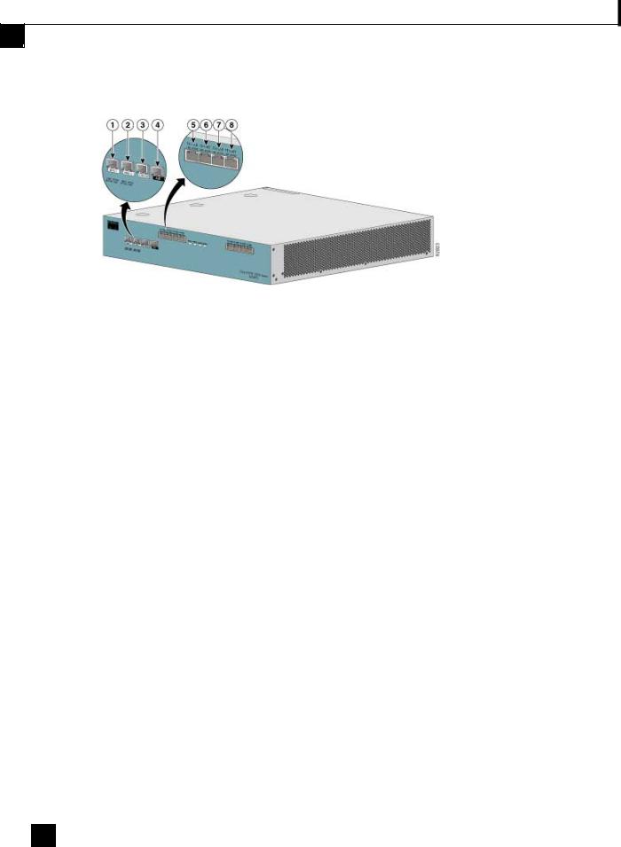
Front Panel
The SCE 2000 Front Panel consists of ports and LEDs as shown in the following figure and tables.
Note Ports FE-3 and FE-4 currently have no software support.
Cisco SCE 2000 4/8xFE Installation and Configuration Guide
|
OL-7826-05 |
2-1 |
|
|
|
Chapter 2 Introduction to the SCE Platform
Front Panel
Figure 2-1: SCE Platform Front Panel
Table 2-2 |
SCE 2000 Ports |
|
|
|
|
|
|
Port |
Quantity |
Description |
Connect This Port To… |
|
|
|
|
Mng1/ |
2 |
10/100/1000 Ethernet RJ-45 ports for |
A LAN using an FE cable |
Mng2 |
|
management of the SCE 2000. |
with an RJ-45 connector. |
|
|
CLI designation: interface Management |
If both interfaces are used to |
|
|
0/1, 0/2. |
provide a redundant |
|
|
|
management interface, |
|
|
|
connect both ports to the LAN |
|
|
|
via a switch. |
|
|
|
|
Console |
1 |
RS-232 RJ-45 port for use by technicians |
A local terminal (console) |
|
|
|
using an RS-232 cable with |
|
|
|
an RJ-45 connector, as |
|
|
|
provided in the SCE 2000 kit. |
|
|
|
|
AUX |
1 |
RS-232 RJ-45 port used by technicians |
|
|
|
|
|
FE-1 |
4 |
FastEthernet RJ-45 ports for connecting |
Refer to Connecting the Line |
SUB/NET |
|
to the line and/or cascading two devices |
Ports ("Connecting the line |
FE-2 |
|
CLI designation: interface FastEthernet |
ports to the network" on page |
|
6-1) for cabling diagrams for |
||
SUB/NET |
|
0/1 through 0/4 |
|
|
various topologies |
||
|
|
|
|
|
|
|
|
FE-3 |
4 |
FastEthernet RJ-45 ports for future use. |
|
SUB/NET |
|
These ports currently have no software |
|
|
|
|
|
FE-4 |
|
support. |
|
SUB/NET |
|
|
|
|
|
|
|
Cisco SCE 2000 4/8xFE Installation and Configuration Guide
2-2 |
OL-7826-05 |
|
|
|
|

Chapter 2 Introduction to the SCE Platform
Front Panel
Table 2-3 |
SCE 2000 LED Groups |
|
|
|
|
LED Groups |
|
Description |
|
|
|
Power A |
|
• Continuous green — Power supply A is functioning normally |
|
|
• Red — Power supply A present, but malfunctioning |
|
|
• Unlit — Power supply A is either not present or has failed. |
|
|
|
Power B |
|
• Continuous green — Power supply B is functioning normally |
|
|
• Red — Power supply B present, but malfunctioning |
|
|
• Unlit — Power supply B is either not present or has failed. |
|
|
The Status LED indicates the operational status of the SCE 2000 system, as |
Status |
|
|
|
|
follows: |
|
|
• Unlit — indicates no power from either power unit. |
|
|
• Orange — indicates that the system is booting up. |
|
|
• Flashing green — indicates that the system is fully operational. |
|
|
• Flashing orange — indicates that the system is operational, but is in a warning |
|
|
state. |
|
|
• Red — indicates that there is a problem or failure |
|
|
Note that Alarms are hierarchical: Failure takes precedence over Warning, which |
|
|
takes precedence over operational. |
|
|
|
Bypass |
|
• Continuous green — indicates that the traffic bypasses the SCE 2000 through |
|
|
an internal electrical bypass module. |
|
|
Single SCE 2000 topology — The SCE 2000 is either in bypass or sniffing |
|
|
mode |
|
|
Cascaded topology — Either the SCE 2000 is forwarding traffic to the other |
|
|
SCE 2000, where it is being processed, or is simply in bypass mode, so traffic |
|
|
through it is not being processed. |
|
|
• Unlit — traffic is not being bypassed |
|
|
Single SCE 2000 topology — indicates normal operation of the SCE 2000 |
|
|
Cascaded topology — indicates normal operation of the active SCE 2000 |
|
|
The FE LEDs indicate the operational status of the SCE 2000 line ports, as |
FE ports |
|
|
|
|
follows: |
|
|
• Active — Flashing green indicates that there are packets being received or |
|
|
transmitted. |
|
|
• Link — Continuous yellow indicates that the system has identified a signal at |
|
|
the port. |
|
|
|
Cisco SCE 2000 4/8xFE Installation and Configuration Guide
|
OL-7826-05 |
2-3 |
|
|
|
Chapter 2 Introduction to the SCE Platform
Back Panel
LED Groups |
Description |
|
|
Mng |
The Mng port LEDs indicate the operational status of the SCE 2000 out-of-band |
|
LAN-based management port, as follows: |
|
• Link/Active |
|
Green — indicates that the port link is up |
|
Unlit — indicates that the port link is down |
|
• 10/100/1000 |
|
Steady green — indicates that the port is set to 100 Mbps |
|
Unlit — indicates that the port is set to 10 Mbps |
|
Flashing Green — indicates that the port is set to 1000 Mbps |
|
|
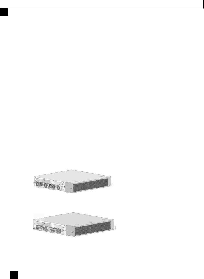
Back Panel
The SCE 2000 platform back-panel contains the following components:
•Two field-replaceable power supply units with ON/OFF switches
•A field-replaceable fan drawer
•Ground connections
The rear panels of both the ACand DC-powered SCE 2000 platforms are shown in the following pair of figures.
Figure 2-2: SCE Platform Back Panel: AC Power
Figure 2-3: SCE Platform Back Panel: DC power
Cisco SCE 2000 4/8xFE Installation and Configuration Guide
2-4 |
OL-7826-05 |
|
|
|
|

Chapter 2 Introduction to the SCE Platform
Checking the Shipping Container Contents 
Checking the Shipping Container Contents
Use the SCE 2000 Component List to check the contents of the SCE 2000 platform shipping container.
Do not discard the shipping container. You need the container if you move or ship the SCE 2000 platform in the future.
Table 2-4 |
SCE 2000 Components List |
|
|
|
|
Component |
Description |
Received |
|
|
|
SCE 2000 |
SCE 2000 platform configured with either AC or DC power |
|
platform |
supplies. |
|
|
|
|
Accessories |
The following accessories might arrive in separate shipping |
|
|
containers: |
|
• Rack mount |
• Two mounting brackets for 19” rack |
|
kit |
• Six screws (Philips), 8-32 x 3/8” (for attaching the brackets to |
|
|
|
|
|
the SCE 2000 chassis) |
|
|
• supporting mounting brackets for 19” rack |
|
|
• Two crossrail supports for 19” rack with front and back posts |
|
• Management |
• Fast Ethernet cable for connecting to the Management port |
|
cables |
• RS-232 serial cable (DB-9 to RJ-45) for connecting to a local |
|
|
|
|
|
terminal |
|
• Power cables |
Two AC power supply cords, if ordered with AC-input power |
|
|
supply units |
|
• Grounding kit |
• Grounding cable |
|
|
• Two Hex nuts (#¼”) |
|
|
• Two spring washers (#¼”) |
|
• Documentatio |
If ordered, SCE 2000 hardware and software documentation set |
|
n |
and the Cisco Documentation CD-ROM package* |
|
|
|
|
Optional |
Four rubber feet for tabletop installation |
|
Equipment |
|
|
|
|
|
*Titles and quantities of documents will vary. You must order the type and quantity of documentation sets when you order the hardware.
Note We no longer ship the entire SCE 2000 documentation set automatically with each system. You must specifically order the documentation as part of the sales order. If you ordered documentation and did not receive it, we will ship the documents to you within 24 hours. To order documents, contact a customer service representative.
Cisco SCE 2000 4/8xFE Installation and Configuration Guide
|
OL-7826-05 |
2-5 |
|
|
|

Chapter 2 Introduction to the SCE Platform
SCE 2000 Installation Checklist
SCE 2000 Installation Checklist
To assist you with your installation and to provide a historical record of what was done by whom, photocopy the following SCE 2000 Installation Checklist. Indicate when each procedure or verification is completed. When the checklist is completed, place it in your site log along with the other records for your new SCE 2000 platform.
Table 2-5 |
SCE 2000 Installation Checklist |
||
|
|
|
|
Task |
|
Verified |
Date |
|
|
By |
|
|
|
|
|
Date SCE 2000 received |
|
|
|
|
|
|
|
SCE 2000 and all accessories unpacked |
|
|
|
|
|
|
|
Safety recommendations and guidelines reviewed |
|
|
|
|
|
|
|
Topology verified: number of SCE 2000 platforms, number of links, and |
|
|
|
whether inline or receive-only |
|
|
|
|
|
|
|
Installation Checklist copied |
|
|
|
|
|
|
|
Site log established and background information entered |
|
|
|
|
|
|
|
Site power voltages verified |
|
|
|
|
|
|
|
Site environmental specifications verified |
|
|
|
|
|
|
|
Required passwords, IP addresses, device names, and so on, needed for |
|
|
|
initial configuration available (refer to Setup Command Parameters (on |
|
|
|
page 5-3)) |
|
|
|
|
|
|
|
Required tools available |
|
|
|
|
|
|
|
Network connection equipment available |
|
|
|
|
|
|
|
SCE 2000 mounted in rack (optional) |
|
|
|
|
|
|
|
AC/DC power cables connected to AC/DC sources and SCE 2000 platform |
|
|
|
|
|
|
|
Console port set for 9600 baud, 8 data bits, no parity, and 1 stop bit (9600 |
|
|
|
8N1) |
|
|
|
|
|
|
|
ASCII terminal attached to console port |
|
|
|
|
|
|
|
FE management ports are operational |
|
|
|
|
|
|
|
FE line and cascade ports operational |
|
|
|
|
|
|
|
Network interface cables and devices connected |
|
|
|
|
|
|
|
System power turned on |
|
|
|
|
|
|
|
System boot complete (SYSTEM–UP LED is on) |
|
|
|
|
|
|
|
Correct hardware configuration displayed after system banner appears |
|
|
|
|
|
|
|
Cisco SCE 2000 4/8xFE Installation and Configuration Guide
2-6 |
OL-7826-05 |
|
|
|
|

C H A P T E R 3
Topology
This chapter describes the possible deployment topologies of the SCE 2000. The Cisco SCE solution offers a number of basic topology options that permit the user to tailor the SCE Platform to fit the needs of a particular installation. An understanding of the various issues and options is crucial to designing, deploying, and configuring the topology that best meets the requirements of the individual system.
This chapter contains the following sections:
• The SCE 2000 Platform |
3-1 |
|
• |
Topology Considerations |
3-1 |
• |
Physical Topologies |
3-4 |
The SCE 2000 Platform
The SCE 2000 introduces a solution for dual links with load sharing and asymmetrical routing and support for fail-over between two SCE platforms.
The SCE 2000 supports wire speed processing of full-duplex 2-Fast Ethernet streams. The SCE 2000 can, therefore, be deployed in a multi-link environment, either in a single or dual SCE platform topology.
•single SCE 2000 topology — Provides increased network capacity and the ability to process both directions of a bi-directional flow, processing both the upstream and downstream paths of a flow, even if they traverse different links
•dual SCE 2000 topology (cascade) — cascaded SCE 2000s provide high-availability and failover solution and maintain the line and service in case of SCE 2000 failure.
Topology Considerations
There are several issues that must be considered in order to arrive at the optimum configuration of the topology-related parameters:
•Functionality — Will the system be used solely to monitor traffic flow, with report functionality only, or will it be used for traffic flow control, with enforcement as well as report functionality?
Cisco SCE 2000 4/8xFE Installation and Configuration Guide
|
OL-7826-05 |
3-1 |
|
|
|

Chapter 3 |
Topology |
Topology Considerations
•Number of links — The SCE 2000 may be connected to one or two FE links. This is relevant for both Inline and Receive-Only topologies.
•Redundancy — Must the system be designed to guarantee uninterrupted SCE 2000 functionality? If so, there must be a backup SCE 2000 Platform to assume operation in case of failure of the primary device.
•Link continuity — How should the SCE 2000 respond to platform failure with regard to link continuity? Should traffic flow continue even though the unit is not operating, or be halted until the platform is repaired/replaced?
These issues determine three important aspects of system deployment and configuration:
•How many SCE 2000 Platforms are needed and how will they be installed?
•Physical topology of the system — The actual physical placement of the SCE 2000 in the system.
•Topology-related configuration parameters — The correct values for each parameter must be ascertained before configuring the system to make sure that the system will function in the desired manner.
Functionality
The SCE 2000 can serve one of two general functions:
•Monitoring and Control — The SCE 2000 monitors and controls traffic flow. Decisions are enforced by the SCE 2000 depending on the results of the monitoring functions of the SCE 2000 and the configuration of the Service Control Application for Broadband or Mobile solution.
In order to perform control functions, the SCE 2000 must be physically installed as an inline installation and the connection mode must be “inline”.
•Monitoring only — The SCE 2000 monitors traffic flow, but cannot control it.
Either an inline installation or an external switch installation may be used for monitoring only. In the latter case connection mode must be “receive-only”.
Numberoflinks
The SCE 2000 can be deployed in a single FE link or in two FE links. The two-link topology may implement load-sharing and the SCE 2000 in this case is able to process both directions of a bidirectional flow even if they split to both links.
Redundancy
When a high degree of reliability is desired, a second SCE 2000 Platform should be installed to provide backup operation capabilities. The combination of two SCE 2000s guarantees uninterrupted functioning in case of a failure of one of the platforms. The two SCE 2000s are cascaded, so that, although all processing is performed only in the active SCE 2000, the standby SCE 2000 is constantly updated with all the necessary information so that it can instantly take over processing the traffic on the data links should the active SCE 2000 fail.
If only preservation of the network links is required, and uninterrupted functionality of the SCE 2000 is not required, a single SCE 2000 is sufficient.
Cisco SCE 2000 4/8xFE Installation and Configuration Guide
3-2 |
OL-7826-05 |
|
|
|
|

|
Chapter 3 |
Topology |
|
Topology Considerations
LinkContinuity
The bypass mechanism of the SCE 2000 allows traffic to continue to flow, if desired, even if the device itself is not functioning.
Note that when the SCE 2000 is connected to the network through an external switch, a failure of the SCE 2000 does not affect the traffic flow, as the traffic continues to flow through the external switch.
Bypass Mechanism
The SCE 2000 includes a Network Interface Card with a bypass mechanism that is enabled upon SCE 2000 failure. In addition, when connected in-line it can also be enabled in normal operation to simultaneously bypass traffic flow to the other side and direct it internally for analysis. In this case it maintains "receive-only"-like monitoring functions, when control functionality is not required.
The bypass card supports the following four modes:
•Bypass — The bypass mechanism preserves the network link, but traffic is not processed for monitoring or for control.
•Forwarding — This is the normal operational mode, in which the SCE 2000 processes the traffic for monitoring and control purposes.
•Sniffing — The bypass mechanism preserves the network link, while in parallel allowing the SCE 2000 to process the traffic for monitoring only.
•Cutoff — There is no forwarding of traffic, and the physical link is forced down (cutoff functionality at layer 1).
Maintaining the Network Links vs Maintaining SCE 2000 Platform Functionality
When a single SCE 2000 is deployed, the user may decide that in case of a failure, maintaining the network link is more important than providing the SCE 2000 functionality. In this scenario, when the SCE 2000 detects a failure that requires a reboot process for recovering, it immediately switches to Bypass mode, allowing all traffic to bypass the SCE 2000. The SCE 2000 stays in Bypass mode maintaining the network link, albeit without SCE 2000 processing, until the SCE 2000 fully recovers from the failure and is ready to resume normal functioning.
Alternatively, the user may decide that the SCE 2000 functionality is sufficiently crucial to require severing the link if the SCE 2000 platform fails. In this case, when the SCE 2000 detects a failure that requires a reboot process for recovering, it immediately switches to Cutoff mode, stopping all traffic flow. The SCE 2000 stays in Cutoff mode, halting all traffic, until it fully recovers from the failure and is ready to resume normal functioning. In Cutoff the physical interface is blocked, enabling the network device connected to the SCE 2000 to sense that the link is down.
Cisco SCE 2000 4/8xFE Installation and Configuration Guide
|
OL-7826-05 |
3-3 |
|
|
|
Chapter 3 |
Topology |
Physical Topologies
Physical Topologies
Following are descriptions of a number of physical topologies that the SCE 2000 supports.
SingleSCE2000Topologies
A single SCE 2000 supports both single FE link and dual FE link topologies.
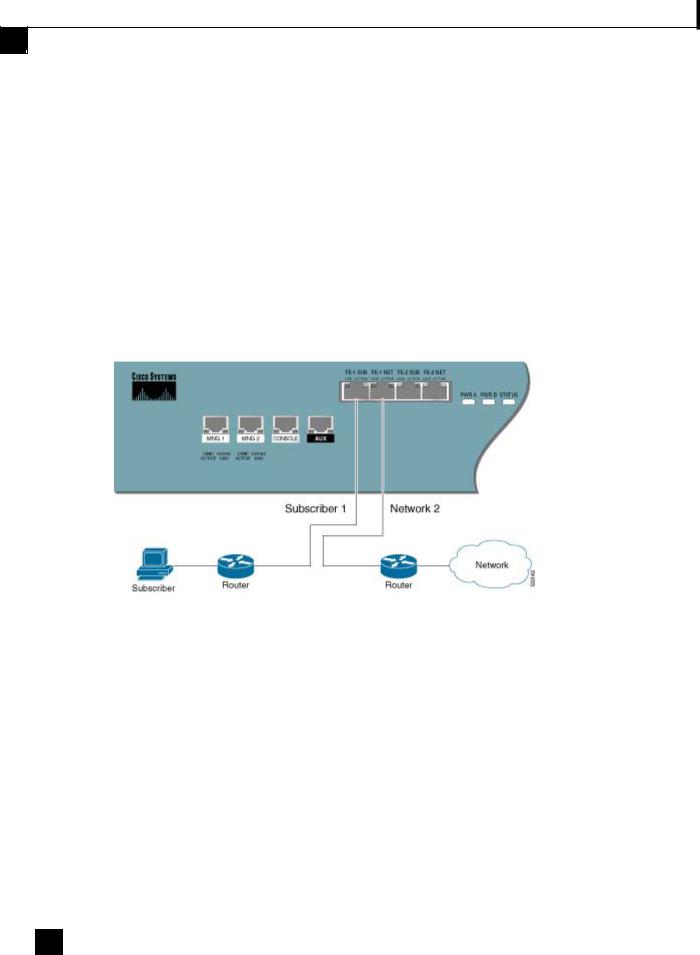
Single Link: Inline Topology
Typically, the SCE 2000 is connected in a full duplex FE link between two devices (Router, BRAS, etc.). When the SCE 2000 is installed as an inline installation, it physically resides on the data link between the subscribers and the network.
Figure 3-1: Single SCE Platform Single Link: In-line Topology
When configuring the SCE 2000, an inline installation is referred to as “inline” connection mode.
Cisco SCE 2000 4/8xFE Installation and Configuration Guide
3-4 |
OL-7826-05 |
|
|
|
|
Loading...