


 Loading...
Quick Start Guide
Cisco PIX 515E Firewall
1Check Items Included
2Install the PIX 515E
3Configure the PIX 515E
4Example Configurations
5Optional Maintenance and Upgrade Procedures
About the Cisco PIX 515E Firewall
The Cisco PIX 515E delivers enterprise-class security for small-to-medium business and enterprise networks, in a modular, purpose-built appliance. Its versatile
one-rack unit (1RU) design supports up to 6 10/100 |
PIX FirewallSERIES |
POWER ACT NETWORK |
Fast Ethernet interfaces, making it an excellent choice
for businesses requiring a cost-effective, resilient security solution with demilitarized zone (DMZ) support. It delivers up to 188 Mbps of firewall throughput with the ability to handle over 130,000 simultaneous sessions. Some PIX 515E models include award-winning high-availability services as well as integrated hardware VPN acceleration, delivering up to 130 Mbps of 3DES and 256-bit AES VPN throughput.
99550
Hardware Features
•433-MHz Intel Celeron processor
•32-MB RAM with the restricted (R) license;
64-MB RAM with the unrestricted (UR) and failover (FO) licenses
•16-MB Flash memory
•128-KB level 2 cache memory at 433 MHz
•32-bit, 33-MHz system bus
•Up to 6 10/100 Fast Ethernet interfaces
•Serial console port for administrative access
•Front panel LEDs for power, failover, and network status
•Up to 188-Mbps firewall throughput
•Supports 56-bit DES, 168-bit 3DES, and 128or 256-bit AES data encryption to ensure data privacy
•Up to 60/130-Mbps VPN throughput (VAC/VAC+)
Software Features
•Includes Cisco PIX Device Manager (PDM) for intuitive, web-based administration of PIX Firewalls
•Supports three licensing models with additional host capacity and failover capability
•Internal DHCP server supports up to 256 address leases per interface
•Supports up to 2000 remote access and site-to-site VPN peers
•Supports up to 130,000 simultaneous connections
•Supports up to eight 802.1Q VLAN-based logical interfaces
•Intrusion protection from many different types of popular network-based attacks ranging from malformed packet attacks to DoS attacks
•Delivers highly resilient network security services via award-winning stateful failover on certain PIX 515E models
2

1 Check Items Included
PC terminal adapter (74-0495-01)
Failover serial cable (74-1213-01)
Rubber feet
DO NOT INSTALL INTERFACE |
|
|
|
|
|
|
CARDS WITH POWER APPLIED |
|
|
|
|
|
|
100 Mbps Link |
|
FDX |
100 Mbps Link |
|
FAILOVER |
PIX-515E |
|
|
FDX |
|
|||
10/100 |
ETHERNET 1 |
10/100 |
ETHERNET 0 |
|
|
|
|
CONSOLE |
|
||||
PIX 515E
Blue console cable (72-1259-01)
Yellow Ethernet cable (72-1482-01)
Mounting brackets (700-01170-02 AO SSI-3)
7 flathead screws |
4 cap screws |
4 spacers |
(69-0123-01) |
(69-0124-01) |
(69-0125-01) |
SecurityCisco |
|
|
Product |
|
PIX |
|
ApplianceCD |
|
|
|
|
End |
|
|
|
|
|
|
|
Software |
|
|
||
Safety |
|
Getting |
|
User |
|
|
|
ComplianceGuide |
PIX |
515E |
|
|
License |
|
|
|
|
|
|
||||
Started |
Warranty |
|
|||||
|
and |
Guide |
|
|
|
|
and |
|
|
|
|
|
|
|
|
97955
Documentation
3

2 Install the PIX 515E
DMZ server Switch |
PIX 515E |
|
DMZ |
|
|
Switch |
Inside |
|
|
Outside |
Power |
|
|
|
|
|
cable |
Laptop |
Router |
|
|
|
|
computer |
|
|
|
Internet |
|
Printer |
|
|
Personal |
|
|
computer |
|
|
97998
Follow these steps to install the PIX 515E:
Step 1 Install the rubber feet onto the five, round, recessed areas on the bottom of the chassis.
Note The chassis is also rack-mountable. For rack-mounting and failover instructions, refer to the Cisco PIX Firewall Hardware Installation Guide.
Step 2 Use the yellow Ethernet cable (72-1482-01) provided to connect the outside 10/100 Ethernet interface, Ethernet 0, to a DSL modem, cable modem, or switch.
Step 3 Use the other yellow Ethernet cable (72-1482-01) provided to connect the inside 10/100 Ethernet interface, Ethernet 1, to a switch or hub.
Step 4 Connect the power cable to the rear of the PIX 515E and a power outlet.
Step 5 Power up the PIX 515E. The power switch is located at the rear of the chassis.
Note For additional hardware installation procedures, refer to the Cisco PIX Firewall Hardware Installation Guide.
4
3 Configure the PIX 515E
The PIX 515E comes with a factory-default configuration that meets the needs of most small and medium business networking environments. A default DHCP server address pool is included for hosts on the inside interface. The factory-default configuration on the PIX 515E protects your inside network from unsolicited traffic.
By default, the PIX 515E denies all inbound traffic through the outside interface. Based on your network security policy, you should also consider configuring the PIX 515E to deny all ICMP traffic to the outside interface, or any other interface you deem necessary, by entering the icmp command. For more information about the icmp command, refer to the Cisco PIX Firewall Command Reference.
The PIX 515E contains an integrated web-based configuration tool called the Cisco PIX Device Manager (PDM), that is designed to help you set up the PIX Firewall. PDM is preinstalled on the PIX 515E. To access PDM, make sure that JavaScript and Java are enabled in your web browser. Refer to the Cisco PIX Device Manager Installation Guide for more information on the operating system and web browser environments supported by PDM.
PDM includes a Startup Wizard for simplified initial configuration of your PIX Firewall. With just a few steps, the
PDM Startup Wizard enables you to efficiently create a basic configuration that allows packets to flow through the PIX Firewall from the inside network to the outside network securely. Follow these steps to use the Startup Wizard:
Step 1 If you have not already done so, connect the inside Ethernet 1 interface of the PIX 515E to a switch or hub using the Ethernet cable. To this same switch, connect a PC for configuring the PIX 515E.
Step 2 Configure your PC to use DHCP (to receive an IP address automatically from the PIX 515E) or assign a static IP address to your PC by selecting an address out of the 192.168.1.0 network. (Valid addresses are 192.168.1.2 through 192.168.1.254 with a mask of 255.255.255.0 and default route of 192.168.1.1.)
Note The inside interface of the PIX 515E is assigned 192.168.1.1 by default, so this address is unavailable.
Step 3 Check the LINK LED on the PIX 515E Ethernet 1 interface. When connectivity occurs, the LINK LED on the Ethernet 1 interface of the PIX Firewall and the corresponding LINK LED on the switch or hub lights up solid green.
5

Step 4 To access the Startup Wizard, use the PC connected to the switch or hub and enter the URL https://192.168.1.1/startup.html into your Internet browser.
Note Remember to add the “s” in “https” or the connection fails. HTTPS (HTTP over SSL) provides a secure connection between your browser and the PIX 515E.
Step 5 Leave both the username and password boxes empty. Press Enter.
Step 6 Select Yes to accept the certificates and follow the instructions in the Startup Wizard to set up your PIX 515E. For online Help, click the Help button at the bottom of the Startup Wizard window.
4 Example Configurations
The following section provides configuration examples for two common PIX 515E configuration scenarios: hosting a web server on a DMZ network and establishing a site-to-site VPN connection with other business partners or remote offices. Use these examples to set up your network. Substitute network addresses and apply additional policies as needed.
DMZ Configuration
A demilitarized zone (DMZ) is a neutral zone between private (inside) and public (outside) networks. A DMZ allows you to have a presence on the public Internet, while protecting private network resources that are accessed by users on the public Internet; for example, mail servers or web servers. The illustration below shows a sample network topology that is common to most DMZ implementations using the PIX 515E, in which the web server is on the DMZ interface. HTTP clients from the inside and the outside networks are able to access the web server securely.
In the illustration below, an HTTP client (10.10.10.10) on the inside network initiates HTTP communications with the DMZ web server (30.30.30.30). HTTP access to the DMZ web server is provided for all clients on the Internet; all other communications are denied. The network is configured such that the range of available IP addresses on the DMZ interface are between 30.30.30.50–30.30.30.60. There are two publicly routable IP addresses available, one for the PIX 515E outside interface (209.165.156.10) and one for the translated DMZ server
(209.165.156.11). Because the DMZ server is located on a private DMZ network, it is necessary to translate its private IP address to a public (routable) IP address. This public address allows external clients HTTP access to the DMZ server as though it was located on the Internet. Use PDM to quickly configure your PIX 515E for secure communications between HTTP clients and web servers.
6
HTTP client
|
PIX 515E |
|
|
Inside |
Outside |
Internet |
HTTP client |
10.10.10.0 |
209.165.156.10 |
|
|
|
|
10.10.10.10
DMZ
30.30.30.0  HTTP client
Web server 30.30.30.30
97999
Step 1 Manage IP Pools for Network Translations
For an inside HTTP client (10.10.10.10) to access the web server on the DMZ network (30.30.30.30), it is necessary to define an IP pool (30.30.30.50–30.30.30.60) for the DMZ interface. Similarly, an IP pool for the outside interface (209.165.156.10) is required for the inside HTTP client to communicate with any device on the public network. Use PDM to manage IP pools efficiently and easily to facilitate secure communications between protected network clients and devices on the Internet.
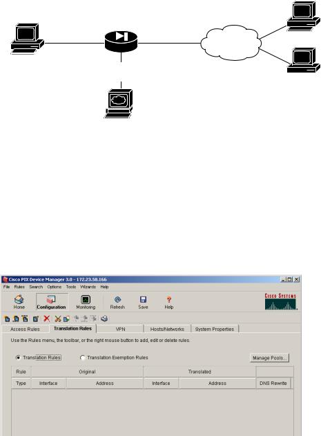
a.Launch PDM.
b.Click the Configuration button at the top of the PDM window.
7
c.Select the Translation Rules tab.
d.Click the Manage Pools button and a new window appears, allowing you to add or edit global address pools.
Note For most configurations, global pools are added to the less secure, or public, interfaces.
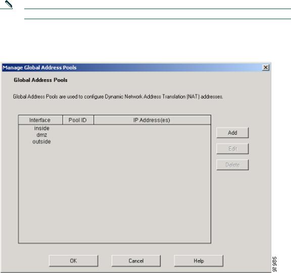
In the Manage Global Address Pools window:
a.Select the dmz interface.
b.Click the Add button.
In the Add Global Pool Item window:
a. Select dmz from the Interface drop-down menu.
8
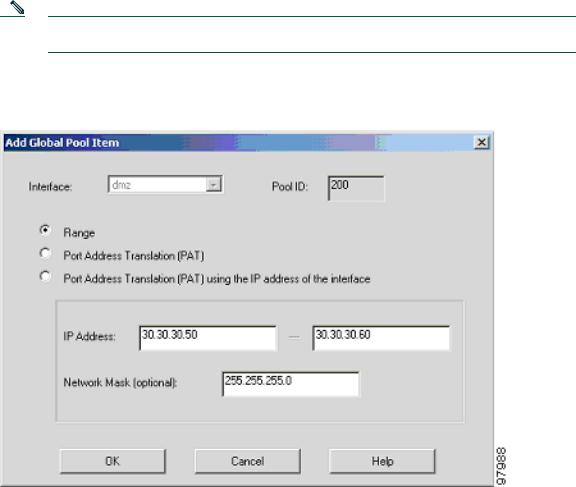
b.Click the Range radio button to enter the IP address range.
c.Because the range of IP addresses for the DMZ interface is 30.30.30.50– 30.30.30.60, enter these values in the two fields.
d.Enter a unique Pool ID (in this case, enter 200).
e.Click the OK button to go back to the Manage Global Address Pools window.
Note You can also select PAT or PAT using the IP address of the interface if there are limited IP addresses available for the DMZ interface.
Because there are only two public IP addresses available, with one reserved for the DMZ server, all traffic initiated by the inside HTTP client exits the PIX 515E using the outside interface IP address. This allows traffic from the inside client to be routed to and from the Internet.
In the Manage Global Address Pools window:
a.Select the outside interface.
b.Click the Add button.
9
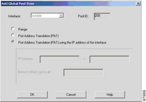
When the new window comes up:
a.Select outside from the Interface drop-down menu.
b.Click the Port Address Translation (PAT) using the IP address of the interface radio button.
c.Assign the same Pool ID for this pool as in Step d above (200).
d.Click the OK button.
Once the pools are configured, confirm their values before applying the rules to the PIX 515E.
Confirm the configurations:
a.Click the OK button.
b.Click the Apply button in the main window.
10
Step 2 Configure Address Translations on Private Networks
Network Address Translation (NAT) replaces the source IP addresses of network traffic traversing between two PIX interfaces. This translation prevents the private address spaces from being exposed on public networks and permits routing through the public networks. Port Address Translation (PAT) is an extension of the NAT function that allows several hosts on the private networks to map into a single IP address on the public network. PAT is essential for small and medium businesses that have a limited number of public IP addresses available to them.
To configure NAT between the inside and the DMZ interfaces for the inside HTTP client, complete the following steps starting from the main PDM page:
a. Select the Translation Rules tab. Ensure that the Translation Rules radio button is selected.
11

b.Right click in the gray area below the Manage Pools button and select Add.
c.In the new window, select the inside interface.
d.Enter the IP address of the client (10.10.10.10).
e.Select 255.255.255.255 from the Mask drop-down menu.
Note You can select the inside host by clicking on the Browse button.
f.Select the DMZ interface on which the translation is required.
g.Click the Dynamic radio button in the Translate Address to section.
h.Select 200 from the Address Pools drop-down menu for the appropriate Pool ID.
i.Click the OK button.
12
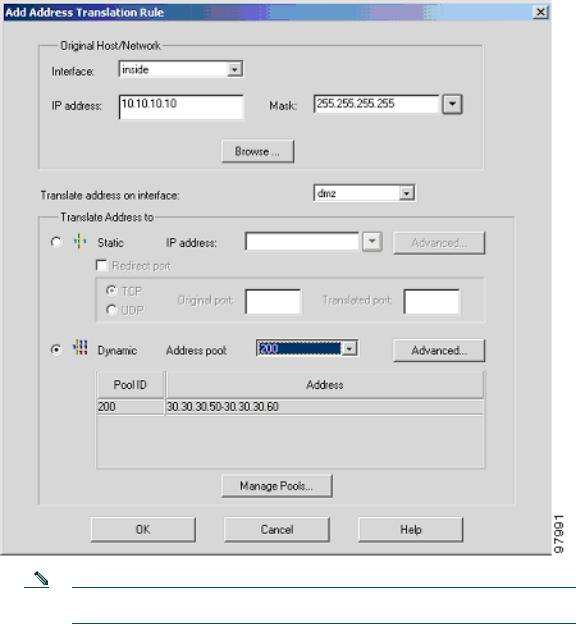
Note Enter the entire network range (10.10.10.0) or select the network using the Browse button and select the Pool ID if there are multiple HTTP clients.
13
Loading...