


Quick Start Guide
Cisco 250 Series Smart Switches

Welcome
Thank you for choosing the Cisco 250 Series Smart Switch. These switches are designed to be operational right out-of-the-box as a standard switch. In the default configuration, it forwards packets between the connecting devices after powered up.
Package Contents
•Cisco 250 Series Smart Switch
•Rackmount Kit
•Power Cord or Adapter
•This Quick Start Guide
•Pointer Card with China RoHS
•Technical Support Contacts
•EU Directives 1999/5/EC Compliance Information (for EU SKU only)
This guide familiarizes you with the smart switch layout and describes how to deploy the switch in your network. For additional information, see www.cisco.com/go/250switches
1 Before You Begin
Before you begin the installation, make sure that you have the following:
•RJ-45 Ethernet cables (Category 5e or higher) for connecting network devices.
•Tools for installing the hardware. The rack-mount kit packed with the switch contains four rubber feet for desktop placement, and two brackets and twelve screws for rack-mounting. If the supplied screws are lost, use replacement screws in the following size:
–Diameter of the screw head: 6.9 mm
–Length of face of screw head to base of screw: 5.9 mm
–Shaft diameter: 3.94 mm
•The wall mount kit includes screws and anchors. If the supplied screws are lost, use replacement screws in the following size:
–Diameter of the screw head: 6.8 mm
–Length of face of screw head to base of screw: 16 mm
–Shaft diameter: 3.5 x 1.3 mm
2 |
Cisco 250 Series Smart Switches |

•Computer with Internet Explorer (version 9.0, 10.0, 11.0), or Firefox (version 36.0, 37.0, or higher), or Chrome (version 40,41,42 or higher) for using the web-based interface.
2 MountingSwitches the Cisco 250 Series Smart
There are three ways to install the switch:
•Place the switch on a flat surface. To place the switch on a desktop, install the four rubber feet (included) on the bottom of the switch.
•Mount the switch in a standard rack (1 rack unit high).
•Mount on a wall.
Placement Tips
Do not mount the device in a location where any of the following conditions exist:
•High Ambient Temperature—To prevent the switch from overheating, do not operate it in an area that exceeds an ambient temperature of 122°F (50°C).
•Air Flow—Both side panels must be unobstructed to prevent overheating.
•Overloading—The device must be level, stable, and secure to prevent it from sliding or shifting out-of-position.
•Circuit Overloading—Adding the device to the power outlet must not overload that circuit.
Rack Mounting
You can mount the switches in any standard size, 19-inch (about 48 cm) wide rack. The switch requires 1 rack unit (RU) of space, which is 1.75 inches (44.45 mm) high.
CAUTION For stability, load the rack from the bottom to the top, with the heaviest devices on the bottom. A top-heavy rack is likely to be unstable and might tip over.
Cisco 250 Series Smart Switches |
3 |
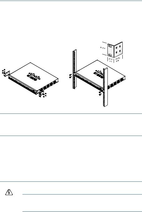
To install the switch into a 19-inch standard chassis:
STEP 1 Place one of the supplied brackets on the side of the switch so that the four holes of the brackets align to the screw holes, and then use the four supplied screws to secure it.
STEP 2 Repeat the previous step to attach the other bracket to the opposite side of the switch.
STEP 3 After the brackets are securely attached, the switch is now ready to be installed into a standard 19-inch rack.
400925
Wall Mounting
To mount the Cisco 250 Series Smart Switches to a wall:
STEP 1 Determine where you want to mount the device. Verify that the surface is smooth, flat, dry, and sturdy.
STEP 2 Drill two pilot holes into the surface of the wall 94 mm apart.
STEP 3 Insert a screw into each hole, leaving a gap between the surface and the base of the screw head.
STEP 4 Place the bottom of the switch over the screws and slide the switch down until the screws fit snugly into the slots.
WARNING Insecure mounting may damage the device or cause injury. Cisco is not responsible for damages incurred by insecure wall or ceiling mounting.
4 |
Cisco 250 Series Smart Switches |

3 Connecting Network Devices
To connect the smart switch to the network:
STEP 1 Connect the Ethernet cable to the Ethernet port of a computer, printer, network storage, or other network device.
STEP 2 Connect the other end of the Ethernet cable to one of the numbered smart switch Ethernet ports.
The LED of the port lights if the device connected is active. Refer to
Features of the Cisco 250 Series Smart Switches for details about the different ports and LEDs on each switch.
STEP 3 Repeat Step 1 and Step 2 for each device you want to connect to the smart switch.
NOTE Cisco strongly recommends using Cat5 or better cable for Gigabit connectivity. When you connect your network devices, do not exceed the maximum cabling distance of 100 meters (328 feet). It can take up to one minute for the attached devices or the LAN to be operational after it is connected. This is normal behavior.
Power over Ethernet Considerations
WARNING The switch is to be connected only to PoE networks without routing to the outside plant.
If your switch is one of the Power over Ethernet (PoE) models, consider the following power requirement:
250 Series Switches with Power Over Ethernet
Model |
Power |
Number of Ports |
PoE Standard |
|
Dedicated to |
Supporting PoE |
Supported |
|
PoE |
|
|
|
|
|
|
SF250-48HP |
195 Watts |
1—48 |
802.3af/at |
|
|
|
|
SG250-10P |
62 Watts |
1—8 |
802.3af/at |
|
|
|
|
SG250-26HP |
100 Watts |
1—24 |
802.3af/at |
|
|
|
|
SG250-26P |
195 Watts |
1—24 |
802.3af/at |
|
|
|
|
Cisco 250 Series Smart Switches |
5 |
 Loading...