


 Loading...
QUICK START GUIDE
Cisco SCE8000 QUICK START GUIDE
Revised: December, 2008, Release 3.1.7, OL-16595-02
Contents
1Prepare for Installation
2Rack-Mount the SCE8000 Chassis
3Connect the Power Supply Units
4Connect the Management Interfaces and Perform Initial System Configuration
5Cable the Line Ports
6Completing the Installation
7Troubleshoot Startup Problems
8Obtaining Documentation and Submitting a Service Request

1 Prepare for Installation
This section contains warnings, information about tools and parts, and site preparation information.
Warning
Warning
Warning
Warning
Warning
Warning
Warning
This warning symbol means danger. You are in a situation that could cause bodily injury. Before you work on any equipment, be aware of the hazards involved with electrical circuitry and be familiar with standard practices for preventing accidents.
Only trained and qualified personnel should install, replace, or service this equipment.
Read the installation instructions before you connect the system to its power source.
This unit is intended for installation in restricted access areas. A restricted access area is where access can only be gained by service personnel through the use of a special tool, lock and key, or other means of security, and is controlled by the authority responsible for the location.
Voltage is present on the backplane when the system is operating. To reduce risk of an electric shock, keep hands and fingers out of the power supply bays and backplane areas.
Do not work on the system or connect or disconnect cables during periods of lightning activity.
Before beginning the installation of the SCE8000, read the Regulatory Compliance and Safety Information for the Cisco SCE8000 Platform document.
Site Preparation
•Verify that the power service at the site is suitable for the SCE8000 chassis.
•Print out and have accessible the Site Planning Checklist and the Cisco SCE8000 Installation Checklist, both found in the Cisco SCE8000 Installation and Configuration Guide, for recording information about this installation.
Tools and Parts
Use the following list of tools and parts as a checklist for preparing to install the SCE8000 chassis:
•Number 1 and number 2 Phillips-head screwdrivers
•3/16-inch flat-blade screwdriver
•Tape measure and level
•Masking tape or some other method of marking the desired installation height in the rack
•One grounding lug.
•Two M4 (metric) hex-head screws with locking washers
2
Note The grounding lug and M4 hex-head screws with locking washers are provided in kit 69-0815-01
•One grounding wire.
The grounding wire must be sized according to local and national installation requirements. Depending on the power supply and system, a 12 AWG conductor or larger size wire is required for U.S. installations.
•Crimping tool (must be large enough to accommodate the girth of the grounding lug when crimping the grounding cable into the lug).
•Wire-stripping tool.
•Appropriate cables to connect the SCE8000 to the network and console terminal.
Unpacking the Cisco SCE8000 Chassis
Tip Do not discard the shipping container when you unpack the Cisco SCE8000. Flatten the shipping cartons and store them with the pallet. You will need these containers if you need to move or ship the Cisco SCE8000 in the future.
Perform the following to check the contents of the shipping container:
•Check the contents of the accessories kit against the list of accessories in the Cisco SCE8000 Component List in the Cisco SCE8000 Installation and Configuration Guide and the packing slip. Verify that you received all listed equipment, which should include the following:
–Hardware and software documentation, if ordered
–Optional equipment that you ordered, such as network interface cables, transceivers, or special connectors
Check the modules in each slot. Ensure that the configuration matches the packing list and that all the specified interfaces are included.
3
2 Rack-Mount the SCE8000 Chassis
This chapter provides information for rack-mounting the SCE8000 chassis.
Warning |
|
Before you install, operate, or service the system, read the Regulatory Compliance and Safety Information for the |
|
|
|
|
Cisco SCE8000 Platform. This guide contains important safety information you should know before working with |
|
|
|
the system. |
|
|
|
|
|
|
|
|
Note |
Before starting the installation procedures in this chapter, see the Site Planning Checklist to verify that all site planning |
||
|
|
activities were completed. |
|
|
|
|
|
Installation Guidelines
Make sure to carefully check the contents of the shipping container, the accessories kit and any optional equipment.
Table 1 |
Equipment Rack Dimensions |
|
|
|
|
|
|
Width |
|
17.75 inches (45.09 cm) |
|
|
|
|
|
Depth |
|
• |
Minimum: 19.25 inches (48.9 cm) |
|
|
• |
Maximum 32 inches (81.3 cm) |
|
|
||
Minimum vertical clearance |
8.7 inches (22.09 cm) (5 RU) |
||
|
|
|
|
Caution If the rack is on wheels, ensure that the brakes are engaged or that the rack is otherwise stabilized
Note We recommend that you maintain a minimum air space of 6 inches (15 cm) between walls and the chassis air vents and a minimum horizontal separation of 12 inches (30.5 cm) between two chassis to prevent overheating.
The installation hardware is not suitable for use with racks with obstructions (such as a power strip) that could impair access to field-replaceable units (FRUs).
Warning |
To prevent bodily injury when mounting or servicing this unit in a rack, you must take special precautions to ensure |
|
that the system remains stable. The following guidelines are provided to ensure your safety: |
|
>This unit should be mounted at the bottom of the rack if it is the only unit in the rack. |
|
>When mounting this unit in a partially filled rack, load the rack from the bottom to the top with the heaviest |
|
component at the bottom of the rack. |
|
>If the rack is provided with stabilizing devices, install the stabilizers before mounting or servicing the unit in the |
|
rack. |
|
|
4
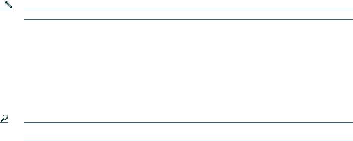
The chassis is shipped with the mounting brackets installed on the front of the chassis. You can remove these brackets and install them on the rear of the chassis, using the holes provided in the rear side of the chassis
Figure 1 .Brackets on Cisco SCE8000 Chassis
FAN |
STATUS |
SCE8000-SCM-E |
|
|
|
|
SCM 1 |
|
|
|
OPTICAL |
|
|
BYPASS |
|
|
SCE8000-SCM-E |
|
SCM 2 |
|
|
|
OPTICAL |
|
|
BYPASS |
|
|
SCE8000-SIP |
|
SIP 3 |
|
SCE |
4 |
|
8000-FAN |
|
|
|
|
CONSOLE |
PORT 1 |
|
|
|
|
|
|
10 100 |
LINK |
STATUS |
|
|
|
|
1000 |
A |
OPTICAL BYPASS |
|
|
|
|
|
CTIVE |
|
|
|
|
|
|
|
OPTICAL |
|
|
|
|
|
|
BYPASS |
AUX |
|
|
|
|
|
|
PORT 2 |
||
|
|
|
|
|
10 100 |
LINK |
|
|
|
|
|
1000 |
ACTIVE |
CONSOLE |
PORT 1 |
|
|
|
|
|
|
10 100 |
LINK |
STATUS |
|
|
|
|
1000 |
A |
OPTICAL BYPASS |
|
|
|
|
|
CTIVE |
|
|
|
|
|
|
|
OPTICAL |
|
|
|
|
|
|
BYPASS |
AUX |
|
|
|
NK |
|
|
PORT 2 |
||
ACTIVE/LI |
|
|
|
|||
|
|
|
|
|
10 100 |
LINK |
|
|
|
|
|
1000 |
ACTIVE |
|
K |
|
|
|
|
|
VE/LIN |
|
SPA- |
|
|
|
|
ACTI |
|
|
|
|
|
|
|
|
|
1X10GE-L-V2 |
|
|
|
|
|
|
|
/LINK |
|
|
|
|
|
|
ACTIVE |
|
|
SPA- |
1X10GE-L-V2 |
|
|
|
|
LINK |
|
|
|
|
ACTIVE/ |
TX |
TX |
|
|
|
|
|
|
|
|
RX |
TX |
A |
C |
|
TX |
CTRL |
|||
|
RX |
B |
D |
|
|
RX |
A |
B |
|
|
RX |
C |
D |
|
OPTICAL |
STATUS |
|
|
|
BYPASS1 |
OPB- |
SCE8K- |
TX |
|
|
|
MM |
|
TX |
|
|
|
RX |
TX |
|
|
|
TX |
|
|
|
|
|
RX |
|
|
|
|
RX |
|
|
|
|
RX |
|
|
|
|
OPTICAL |
|
|
|
|
BYPASS2 |
SCE8000 |
EXTENDED SERVICE |
|
|
|
CONTROL MODULE |
|
MASTER |
SYSTEM POWER |
|
SCE8000 |
EXTENDED SERVICE |
|
|
|
CONTROL MODULE |
|
MASTER |
SYSTEM POWER |
|
SPA- |
1X10GE-L-V2 |
SPA- |
1X10GE-L-V2 |
A |
C |
CTRL |
B |
D |
|
A |
B |
|
C |
D |
|
STATUS |
|
|
OPB-SCE8K-MM
270890
Step 1 Position the chassis in the rack as follows:
•If the front of the chassis (front panel) is at the front of the rack, insert the rear of the chassis between the mounting posts.
•If the rear of the chassis is at the front of the rack, insert the front of the chassis between the mounting posts.
Step 2 Align the mounting holes in the bracket (and optional cable guide) with the mounting holes in the equipment rack.
5
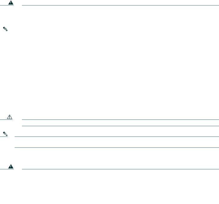
Step 3 Use a tape measure and level to choose and mark the position that the chassis is to be installed in the rack. Make a mark at equal height on both sides of the rack. This will help ensure that the chassis will be installed straight and level.
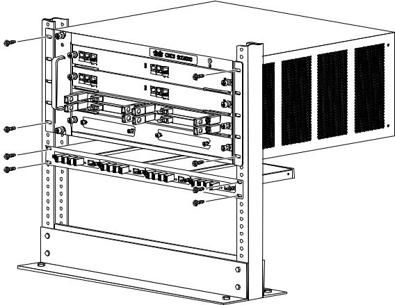
Figure 2 Installing the Cisco SCE8000 Chassis in the Rack
FAN |
STATUS |
SCE8000-SCM-E |
|
|
|
|
|
|
|
|
|
|
|
|
|
|
|
|
|
|
|
|
|
|
|
||
|
SCM |
1 |
|
|
|
|
|
|
|
|
|
|
|
|
|
|
OPTICAL |
|
|
|
|
|
|
|
|
|
|
|
|
|
BYPASS |
CONSOLE |
|
|
|
|
|
|
|
|
|
|
|
|
|
PORT 1 |
|
|
|
|
|
|
|
||
|
|
|
|
1000 |
LINK |
STATUS |
|
|
|
|
|
|
|
|
|
|
|
10 |
100 |
|
OPTICAL BYPASS |
|
|
|
|
|
|
|
|
|
|
|
|
ACTIVE |
|
|
|
|
|
|
|
|
|
|
SCE8000-SCM-E |
|
|
|
OPTICAL |
|
|
|
|
|
|
|
|
|
|
|
|
|
|
|
|
SCE8000 EXTENDED |
|
|
|
|
|
|
|
|
|
|
BYPASS |
AUX |
|
|
SERVICE CONTROL |
MODULE |
|
|
SCM |
2 |
|
|
|
|
|
|
PORT 2 |
|
|
||
|
|
|
|
|
|
|
10 100 |
LINK |
|
|
|
||
|
|
|
|
|
|
|
|
1000 |
MASTER |
|
|||
|
|
|
|
|
|
|
|
|
|
ACTIVE |
|
||
|
|
|
OPTICAL |
|
|
|
|
|
|
|
SYSTEM POWER |
|
|
|
|
|
BYPASS |
CONSOLE |
|
|
|
|
|
|
|
|
|
|
|
|
|
PORT 1 |
|
|
|
|
|
|
|
||
|
|
|
|
1000 |
LINK |
STATUS |
|
|
|
|
|
|
|
|
|
|
|
10 |
100 |
|
OPTICAL BYPASS |
|
|
|
|
|
|
|
|
|
|
|
|
ACTIVE |
|
|
|
|
|
|
|
|
|
|
SCE8000-SIP |
|
|
|
|
|
|
|
|
|
|
|
|
|
|
|
|
|
OPTICAL |
|
|
|
SCE8000 EXTENDED |
|
|
|
|
|
|
|
|
|
BYPASS |
AUX |
|
|
SERVICE CONTROL |
|
|
|
|
|
|
|
|
|
|
PORT 2 |
|
MODULE |
|||
|
SIP |
3 |
|
|
|
|
|
|
10 100 |
LINK |
MASTER |
|
|
|
|
|
|
|
|
|
|
|
1000 |
ACTIVE |
|
||
|
|
|
|
|
|
|
|
|
|
|
SYSTEM POWER |
|
|
|
|
|
|
|
|
|
SPA-1X10GE-L-V2 |
|
|
|
|
|
|
|
|
|
|
|
|
|
SPA-1X10GE-L-V2 |
|
|
|
|
|
|
|
4 |
TX |
|
|
|
|
|
|
|
|
|
SPA-1X10GE-L-V2 |
SCE8000- |
|
|
TX |
|
|
|
|
|
|
|
|
|
|
FAN |
|
TX |
|
|
|
|
|
|
|
|
|
|
RX |
TX |
A |
C |
CTRL |
|
|
|
|
|
||
|
|
|
RX |
B |
D |
|
|
|
|
|
||
|
|
|
RX |
A |
B |
|
|
|
|
|
|
SPA-1X10GE-L-V2 |
|
|
|
RX |
C |
D |
|
|
|
|
|
|
|
|
|
|
OPTICAL |
STATUS |
OPB- |
|
|
|
|
|
|
|
|
|
|
|
|
|
TX |
|
|
|
|
||
|
|
|
BYPASS1 |
|
|
SCE8K-MM |
TX |
|
|
|
||
|
|
|
|
|
|
|
|
RX |
TX |
A |
C |
|
|
|
|
|
|
|
|
|
TX |
CTRL |
|||
|
|
|
|
|
|
|
|
|
RX |
B |
D |
|
|
|
|
|
|
|
|
|
|
RX |
A |
B |
|
|
|
|
|
|
|
|
|
|
RX |
C |
D |
|
OPTICAL |
BYPASS2 |
STATUS |
|
OPB-SC |
|
|
|
E8K-MM |
270891
Step 4 Install the eight (four per side) 12-24 x 3/4-inch or 10-32 x 3/4-inch screws through the holes in the bracket and into the threaded holes in the equipment rack posts.
Step 5 Use a tape measure and level to verify that the chassis is installed straight and level.
Installing an Optical Bypass Module
There are two installation options for the external bypass modules:
•Chassis mount panel—This panel is mounted on slot #4 of the SCE8000 chassis. It hosts two optical bypass modules, which will serve the two traffic links supported by one Cisco SCE8000 chassis.
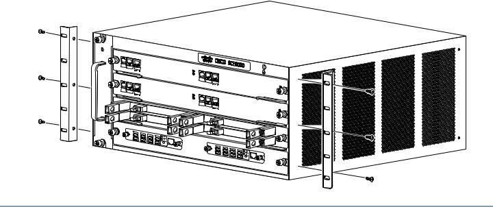
•External mounting panel—This panel can be mounted in any 19" rack. It hosts up to four optical bypass modules, which will serve the four traffic links supported by two Cisco SCE8000 platforms.
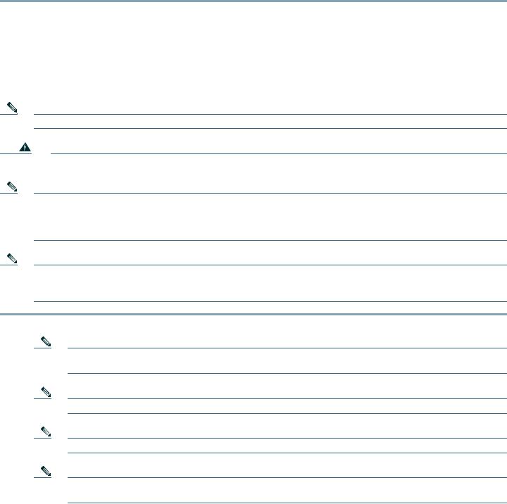
Step 1 For external mounting, install the external mounting panel in the 19" rack. Screw the mounting panel to the rack using four 3/4-inch screws, two on each side, through the holes in the mounting panel and into the threaded holes in the rack posts.
For internal mounting, the SCE8000 chassis will be shipped with the chassis mounting panel already installed in slot #4.
Step 2 Remove the module filler plate covering the subslot in the mounting panel by loosening the two screws.
6
Step 3 Carefully insert the optical bypass module into the subslot (there are no guide rails) and tighten the captive screws on either side of the module.
Figure 3 Optical Bypass Modules in External Mounting Panel
FAN |
STATUS |
SCE8000-SCM-E |
|
|
|
|
|
|
|
|
|
|
SCM 1 |
|
|
|
|
|
|
OPTICAL |
|
|
|
|
|
BYPASS |
CONSOLE |
|
|
|
|
|
PORT 1 |
||
|
|
|
|
10 100 |
LINK |
|
|
|
|
1000 |
ACTIVE |
|
|
SCE8000-SCM-E |
|
|
|
|
SCM 2 |
|
|
|
|
|
|
OPTICAL |
|
|
|
|
|
BYPASS |
CONSOLE |
|
|
|
|
|
PORT 1 |
||
|
|
|
|
10 100 |
LINK |
|
|
|
|
1000 |
ACTIVE |
|
|
SCE8000-SIP |
|
|
|
|
SIP 3 |
|
|
|
|
|
4 |
|
|
|
|
SCE8000-FAN |
|
|
|
|
|
STATUS |
|
|
|
OPTICAL BYPASS |
|
|
|
OPTICAL |
|
|
|
BYPASS |
AUX |
PORT 2 |
|
|
|
10 100 |
LINK |
|
|
1000 |
ACTIVE |
STATUS |
|
|
|
OPTICAL BYPASS |
|
|
|
OPTICAL |
|
|
|
BYPASS |
AUX |
|
|
|
PORT 2 |
||
|
|
10 100 |
LINK |
|
|
1000 |
ACTIVE |
SPA-1X10GE-L-V2 |
|
|
|
SPA-1X10GE-L-V2 |
|
|
|
SCE8000 |
EXTENDED SERVICE |
|
CONTROL MODULE |
|
MASTER |
SYSTEM POWER |
|
SCE8000 |
EXTENDED SERVICE |
|
|
|
CONTROL MODULE |
|
MASTER |
SYSTEM POWER |
|
SPA-1X10GE-L-V2 |
SPA-1X10GE-L-V2 |
270994
7

3 Connect the Power Supply Units
.The SCE8000 chassis is shipped with the power supplies (AC or DC) already installed. This section provides information for grounding the SCE8000 platform and connecting the AC or DC power supply units
Connect the Chassis Ground
Note You must connect the system ground on both ACand DC-powered systems to an earth ground if this equipment is installed in a US or European Central Office.
Note For DC-powered systems, the system ground is also the power supply ground. The DC ground must be installed with a permanent connection to an earth ground according to NEC guidelines.
Note There are additional grounding requirements when using the PWR-2700-DC/4 power supply in the Cisco SCE8000 chassis.
Two threaded M4 holes are provided on the chassis frame to attach the ground cable.
You must complete this procedure before connecting system power or turning on the Cisco SCE8000 chassis.
Step 1 Use a wire-stripping tool to remove approximately 0.75 inch (19 mm) of the covering from the end of the grounding wire.
Step 2 Insert the stripped end of the grounding wire into the open end of the grounding lug.
Step 3 Use the manufacturer recommended crimping tool to secure the grounding wire in place in the grounding lug.
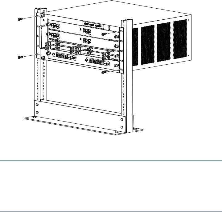
Step 4 Locate and remove the adhesive label from the system grounding pad on the chassis.
Figure 4 Installing the System Ground
Grounding |
System ground |
|
connector |
|
|
lug |
|
|
|
Wire |
System ground |
|
connector |
|
|
|
FAN |
STATUS |
SCE8000-SCM-E |
|
|
|
|
SCM 1 |
|
|
|
OPTICAL |
|
|
BYPASS |
|
|
SCE8000-SCM-E |
|
SCM 2 |
|
|
|
OPTICAL |
|
|
BYPASS |
|
|
SCE8000-SIP |
|
SIP 3 |
|
S |
4 |
|
|
|
|
CE8000-FAN |
|
|
CONSOLE |
PORT 1 |
|
|
|
|
|
1000 |
LINK |
STATUS |
|
|
|
|
10 |
100 |
|
OPTICAL BYPASS |
|
|
|
|
|
ACTIVE |
|
|
|
|
|
|
|
OPTICAL |
|
|
|
|
|
|
BYPASS |
AUX |
|
|
|
|
|
|
|
PORT 2 |
|
|
|
|
|
|
10 100 |
LINK |
|
|
|
|
|
1000 |
ACTIVE |
CONSOLE |
PORT 1 |
|
|
|
|
|
10 100 |
LINK |
STATUS |
|
|
|
|
1000 |
A |
OPTICAL BYPASS |
|
|
|
|
|
|
CTIVE |
|
|
|
|
|
|
|
OPTICAL |
|
|
|
|
|
|
BYPASS |
AUX |
|
|
/LINK |
|
|
|
PORT 2 |
||
ACTIVE |
|
|
|
|
||
|
|
|
|
|
10 100 |
LINK |
|
|
|
|
|
1000 |
ACTIVE |
/LINK |
|
|
|
|
|
|
ACTIVE |
|
|
SPA- |
|
|
|
|
|
|
1X10GE-L-V2 |
/LINK |
|
|
|
|
|
|
|
|
|
|
|
|
|
ACTIVE |
|
|
SPA- |
1X10GE-L-V2 |
|
|
|
|
|
|
|
/LINK |
|
|
|
|
|
|
|
|
|
ACTIVE |
|
|
TX |
TX |
|
|
|
|
|
|
|
|
RX |
TX |
A |
C |
|
|
|
|
|
|
TX |
CTRL |
|
|
|
|
||||
|
RX |
B |
D |
|
|
|
|
||
|
RX |
A |
B |
|
|
|
|
|
|
|
RX |
C |
D |
|
|
|
|
|
|
|
OPTICAL |
STATUS |
OPB- |
|
|
|
|
|
|
|
B |
|
|
SCE8K- |
|
TX |
|
|
|
|
YPASS1 |
|
|
|
MM |
TX |
|
||
|
|
|
|
|
|
|
RX |
TX |
TX |
|
|
|
|
|
|
|
RX |
||
|
|
|
|
|
|
|
|
RX |
RX |
|
|
|
|
|
|
|
|
|
|
|
|
|
|
|
|
|
|
OPTICAL |
BYPASS2 |
|
|
|
|
|
|
|
|
|
|
SCE8000 |
EXTENDED SERVICE |
|
|
|
CONTROL MODULE |
|
MASTER |
SYSTEM POWER |
|
SCE8000 |
EXTENDED SERVICE |
|
|
|
CONTROL MODULE |
|
MASTER |
SYSTEM POWER |
|
SPA- |
1X10GE-L-V2 |
SPA- |
1X10GE-L-V2 |
A |
C |
CTRL |
B |
D |
|
A |
B |
|
C |
D |
|
STATUS |
|
|
OPB-SCE8K-MM
270892
8
Step 5 Place the grounding wire lug against the grounding pad, making sure there is solid metal-to-metal contact.
Step 6 Secure the grounding lug to the chassis with two M4 screws. Ensure that the grounding lug will not interfere with other hardware or rack equipment.
Step 7 Prepare the other end of the grounding wire, and connect it to an appropriate grounding point in your site to ensure adequate earth ground for the Cisco SCE8000 chassis.
Connecting the Power
The following sections describe how to reconnect the AC or DC power.
Installing a DC-Input Power Supply
Note The DC return must remain isolated from the system frame and chassis (DC-I).
Warning |
Before performing any of the following procedures, ensure that power is removed from the DC circuit. |
Note As the power requirement of the SCE8000 will not exceed 1350W, it is not necessary to connect two pairs of input wires to each power supply. Should it be desired to connect two pairs of input wires, both pairs of input wires for one 2700W DC-input power supply must come from the same battery system (A feed); and both pairs of input wires for the other power supply must come from another battery system (B feed).
Note For multiple DC input power supply, each DC input must be protected by dedicated circuit breaker or fuse. The circuit breaker or fuse should be sized according to the power supply input rating and local or national electrical code requirements.
Step 1 Power supply ground is required. Install the PWR-2700-DC/4 power supply ground as described in this procedure.
Note The system ground connection with the PWR-2700-DC/4 power supply in a Cisco SCE8000 is provided by the PWR-2700-DC/4 power supply ground. Additionally, you can connect a system (earth) ground.
Note You must always connect the PWR-2700-DC/4 power supply ground.
Note You must always connect the PWR-2700-DC/4 power supply ground for both power supplies.
Note If you intend to use an additional system (earth ground), ensure that the system ground connection has been made. For ground connection installation instructions, see Connect the Chassis Ground, page 8.
Step 2 Remove the plastic bag attached to the front panel and put aside. This bag contains two plastic terminal block barriers, two cable ties, and two cable holder covers.
9
Loading...