


 Loading...
Cisco Aironet 1550 Series Outdoor Mesh Access Point Hardware Installation Guide
April 2011
Revised February 20, 2013
Americas Headquarters
Cisco Systems, Inc. 170 West Tasman Drive
San Jose, CA 95134-1706 USA http://www.cisco.com Tel: 408 526-4000
800 553-NETS (6387) Fax: 408 527-0883
Text Part Number: OL-24247-01
THE SPECIFICATIONS AND INFORMATION REGARDING THE PRODUCTS IN THIS MANUAL ARE SUBJECT TO CHANGE WITHOUT NOTICE. ALL STATEMENTS, INFORMATION, AND RECOMMENDATIONS IN THIS MANUAL ARE BELIEVED TO BE ACCURATE BUT ARE PRESENTED WITHOUT WARRANTY OF ANY KIND, EXPRESS OR IMPLIED. USERS MUST TAKE FULL RESPONSIBILITY FOR THEIR APPLICATION OF ANY PRODUCTS.
THE SOFTWARE LICENSE AND LIMITED WARRANTY FOR THE ACCOMPANYING PRODUCT ARE SET FORTH IN THE INFORMATION PACKET THAT SHIPPED WITH THE PRODUCT AND ARE INCORPORATED HEREIN BY THIS REFERENCE. IF YOU ARE UNABLE TO LOCATE THE SOFTWARE LICENSE OR LIMITED WARRANTY, CONTACT YOUR CISCO REPRESENTATIVE FOR A COPY.
The following information is for FCC compliance of Class A devices: This equipment has been tested and found to comply with the limits for a Class A digital device, pursuant to part 15 of the FCC rules. These limits are designed to provide reasonable protection against harmful interference when the equipment is operated in a commercial environment. This equipment generates, uses, and can radiate radio-frequency energy and, if not installed and used in accordance with the instruction manual, may cause harmful interference to radio communications. Operation of this equipment in a residential area is likely to cause harmful interference, in which case users will be required to correct the interference at their own expense.
The following information is for FCC compliance of Class B devices: The equipment described in this manual generates and may radiate radio-frequency energy. If it is not installed in accordance with Cisco’s installation instructions, it may cause interference with radio and television reception. This equipment has been tested and found to comply with the limits for a Class B digital device in accordance with the specifications in part 15 of the FCC rules. These specifications are designed to provide reasonable protection against such interference in a residential installation. However, there is no guarantee that interference will not occur in a particular installation.
Modifying the equipment without Cisco’s written authorization may result in the equipment no longer complying with FCC requirements for Class A or Class B digital devices. In that event, your right to use the equipment may be limited by FCC regulations, and you may be required to correct any interference to radio or television communications at your own expense.
You can determine whether your equipment is causing interference by turning it off. If the interference stops, it was probably caused by the Cisco equipment or one of its peripheral devices. If the equipment causes interference to radio or television reception, try to correct the interference by using one or more of the following measures:
•Turn the television or radio antenna until the interference stops.
•Move the equipment to one side or the other of the television or radio.
•Move the equipment farther away from the television or radio.
•Plug the equipment into an outlet that is on a different circuit from the television or radio. (That is, make certain the equipment and the television or radio are on circuits controlled by different circuit breakers or fuses.)
Modifications to this product not authorized by Cisco Systems, Inc. could void the FCC approval and negate your authority to operate the product.
The Cisco implementation of TCP header compression is an adaptation of a program developed by the University of California, Berkeley (UCB) as part of UCB’s public domain version of the UNIX operating system. All rights reserved. Copyright © 1981, Regents of the University of California.
NOTWITHSTANDING ANY OTHER WARRANTY HEREIN, ALL DOCUMENT FILES AND SOFTWARE OF THESE SUPPLIERS ARE PROVIDED “AS IS” WITH ALL FAULTS. CISCO AND THE ABOVE-NAMED SUPPLIERS DISCLAIM ALL WARRANTIES, EXPRESSED OR IMPLIED, INCLUDING, WITHOUT LIMITATION, THOSE OF MERCHANTABILITY, FITNESS FOR A PARTICULAR PURPOSE AND NONINFRINGEMENT OR ARISING FROM A COURSE OF DEALING, USAGE, OR TRADE PRACTICE.
IN NO EVENT SHALL CISCO OR ITS SUPPLIERS BE LIABLE FOR ANY INDIRECT, SPECIAL, CONSEQUENTIAL, OR INCIDENTAL DAMAGES, INCLUDING, WITHOUT LIMITATION, LOST PROFITS OR LOSS OR DAMAGE TO DATA ARISING OUT OF THE USE OR INABILITY TO USE THIS MANUAL, EVEN IF CISCO OR ITS SUPPLIERS HAVE BEEN ADVISED OF THE POSSIBILITY OF SUCH DAMAGES.
Any Internet Protocol (IP) addresses used in this document are not intended to be actual addresses. Any examples, command display output, and figures included in the document are shown for illustrative purposes only. Any use of actual IP addresses in illustrative content is unintentional and coincidental.
Cisco Aironet 1550 Series Outdoor Mesh Access Point Hardware Installation Guide
© 2013 Cisco Systems, Inc. All rights reserved.

|
|
|
|
|
|
|
C O N T E N T S |
|
Preface |
ix |
|
|
|
|
|
|
Objectives |
ix |
|
|
|
|
|
|
Audience ix |
|
|
|
|
||
|
Organization |
x |
|
|
|
|
|
|
Conventions |
x |
|
|
|
|
|
|
Related Documents |
xvi |
|
|
|
||
|
Finding the Product Serial Number |
xvi |
|||||
|
Obtaining Documentation, Support, and Security Guidelines xvii |
||||||
|
Overview |
|
|
|
|
|
|
C H A P T E R 1 |
1-1 |
|
|
|
|
|
|
|
About the 1552 Access Point |
1-1 |
|
||||
|
Hardware Models |
1-2 |
|
|
|
||
|
Regulatory Domains |
1-4 |
|
|
|||
|
Hardware Features |
1-5 |
|
|
|
||
|
Connectors 1-5 |
|
|
|
|||
|
|
1552E/1552EU Connectors |
1-6 |
||||
|
|
1552I Connectors |
1-8 |
|
|||
|
|
1552C/1552CU Connectors |
1-8 |
||||
|
|
Connectors for All Models |
1-10 |
||||
|
Antenna Port Locations |
|
1-11 |
|
|||
|
Multiple Radio Operation |
1-12 |
|
||||
|
Antenna Configurations |
1-13 |
|
||||
|
Low Profile Dual-Band 2.4/5-GHz Omni Antenna Array 1-13 |
|
|
|
|
|
|
Cisco Aironet Dual-Band Omnidirectional Antenna (AIR-ANT2547V-N) 1-14 |
|
|
|
|
|
|
Cisco Aironet 2.4-GHz/5-GHz 8-dBi Directional Antenna (AIR-ANT2588P3M-N) |
1-15 |
|
|
||
|
Cisco Aironet 5-GHz 14-dBi 2-Port Directional Antenna (AIR-ANT5114P2M-N) |
1-16 |
|
|
||
|
Cisco Aironet 2.4-GHz 13-dBi 2-Port Directional Antenna (AIR-ANT2413P2M-N |
1-17 |
|
|
||
|
Cisco Aironet 2.4-GHz 2-dBi Omnidirectional Antenna (AIR-ANT2420V-N) |
1-18 |
|
|
|
|
|
Cisco Aironet 2.4-GHz 5-dBi Omnidirectional Antenna (AIR-ANT2450V-N) |
1-18 |
|
|
|
|
|
Cisco Aironet 2.4-GHz 8-dBi Omnidirectional Antenna (AIR-ANT2480V-N) |
1-19 |
|
|
|
|
|
Cisco Aironet 5-GHz 4-dBi Omnidirectional Antenna (AIR-ANT5140V-N) |
1-20 |
|
|
|
|
|
Cisco Aironet 5-GHz 8-dBi Omnidirectional Antenna (AIR-ANT5180V-N) |
1-20 |
|
|
|
|
|
Multiple Power Sources 1-21 |
|
|
|
|
|
|
Cable Modem (POC) 1-22 |
|
|
|
|
|
|
Cisco Aironet 1550 Series Outdoor Mesh Acces Point Hardware Installation Guide |
|
|
|
||
|
||||||
|
|
|
|
|
|
|
|
OL-24247-01 |
|
|
|
iii |
|
|
|
|
|
|
||

Contents
|
|
|
|
|
Ethernet (PoE) Ports |
1-22 |
|
|
|
|
|
|
|
|||
|
|
|
|
|
Fiber Option |
1-23 |
|
|
|
|
|
|
|
|
|
|
|
|
|
|
|
GPS Option |
1-24 |
|
|
|
|
|
|
|
|
|
|
|
|
|
|
|
Metal Enclosure |
1-24 |
|
|
|
|
|
|
|
|
||
|
|
|
|
|
Optional Hardware |
1-24 |
|
|
|
|
|
|
|
|||
|
|
|
|
|
Network Deployment Examples |
1-25 |
|
|
|
|
|
|
||||
|
|
|
|
|
Wireless Backhaul |
|
1-25 |
|
|
|
|
|
|
|
||
|
|
|
|
|
Point-to-Point Bridging |
1-25 |
|
|
|
|
|
|
|
|||
|
|
|
|
|
Point-to-Multipoint Bridging |
1-26 |
|
|
|
|
|
|
||||
|
|
|
|
|
Point-to-Multipoint Mesh Network |
1-27 |
|
|
|
|
||||||
|
|
|
|
|
Layer 3 Network Operation |
1-28 |
|
|
|
|
|
|
||||
|
|
Installing the Access Point |
|
|
|
|
|
|
|
|
||||||
C H A P T E R 2 |
|
2-1 |
|
|
|
|
|
|
|
|||||||
|
|
|
|
|
Unpacking the Access Point |
2-2 |
|
|
|
|
|
|
|
|||
|
|
|
|
|
Package Contents |
|
2-2 |
|
|
|
|
|
|
|
|
|
|
|
|
|
|
Tools and Hardware |
2-2 |
|
|
|
|
|
|
|
|
||
|
|
|
|
|
Optional Tools and Hardware |
2-2 |
|
|
|
|
|
|
||||
|
|
|
|
|
Optional Tools and Hardware That You Supply |
2-3 |
|
|
|
|||||||
|
|
|
|
|
Pole Installation Hardware and Tools |
2-3 |
|
|
|
|
||||||
|
|
|
|
|
Cable Strand Installation Hardware and Tools |
2-4 |
|
|
|
|||||||
|
|
|
|
|
Warnings 2-4 |
|
|
|
|
|
|
|
|
|
|
|
|
|
|
|
|
Safety Information |
2-5 |
|
|
|
|
|
|
|
|
|
|
|
|
|
|
|
FCC Safety Compliance Statement |
2-5 |
|
|
|
|
||||||
|
|
|
|
|
Safety Precautions |
2-5 |
|
|
|
|
|
|
|
|||
|
|
|
|
|
Avoiding Damage to Radios in a Testing Environment |
2-7 |
|
|
|
|||||||
|
|
|
|
|
Installation Guidelines |
|
2-8 |
|
|
|
|
|
|
|
|
|
|
|
|
|
|
Site Surveys |
2-8 |
|
|
|
|
|
|
|
|
|
|
|
|
|
|
|
Before Beginning the Installation |
2-9 |
|
|
|
|
|
|||||
|
|
|
|
|
Becoming Familiar with Access Point Installation Components |
2-9 |
|
|||||||||
|
|
|
|
|
Opening the Access Point Hinged Cover |
2-13 |
|
|
|
|
||||||
|
|
|
|
|
Closing the Access Point Hinged Cover |
2-13 |
|
|
|
|
||||||
|
|
|
|
|
Mounting the Access Point |
2-14 |
|
|
|
|
|
|
|
|||
|
|
|
|
|
Installation Options |
2-14 |
|
|
|
|
|
|
|
|||
|
|
|
|
|
Access Point Mounting Orientation |
2-15 |
|
|
|
|
||||||
|
|
|
|
|
Installing the Mounting Bracket on a Wall (All Models) |
2-15 |
|
|
||||||||
|
|
|
|
|
Installing the Mounting Bracket on a Pole (All Models) |
2-18 |
|
|
||||||||
|
|
|
|
|
Assembling the Pole Clamp Bracket and the Mounting Bracket 2-18 |
|||||||||||
|
|
|
|
|
Mounting Bracket Assembly on a Pole 2-20 |
|
|
|
||||||||
|
|
|
|
|
Installing 1552E, 1552EU, or 1552I in the Mounting Bracket |
2-23 |
|
|||||||||
|
|
|
|
Cisco Aironet 1550 Series Outdoor Mesh Acces Point Hardware Installation Guide |
|
|
|
|||||||||
|
|
|
|
|
|
|
||||||||||
|
|
|
|
|
|
|
|
|
|
|
|
|
|
|
|
|
|
iv |
|
|
|
|
|
|
|
|
|
|
|
|
|
OL-24247-01 |
|
|
|
|
|
|
|
|
|
|
|
|
|
|
|
|
||

Contents
Installing 1552C or 1552CU in the Mounting Bracket 2-26 |
|
Cable Strand Mounting the 1552C or 1552CU Access Point |
2-26 |
Mounting the 1552C or 1552CU Access Point on a Pole/Wall |
2-30 |
Mounting the 1552C or 1552CU Access Point Facing Up in a Vault Application 2-33 |
|
|
|
Installing Antennas |
2-36 |
|
|
|
|
|
|
|
|
|
|
Antenna N-Type Connector Locations 2-37 |
|
|
|
|
|||||
|
|
Antenna Mounting Options |
2-38 |
|
|
|
|
|
|||
|
|
Safety Precautions |
2-41 |
|
|
|
|
|
|
||
|
|
Grounding the Access Point |
2-41 |
|
|
|
|
|
|
||
|
|
Connecting a Fiber-Optic Cable to the Access Point 2-42 |
|||||||||
|
|
Powering the Access Point |
2-45 |
|
|
|
|
|
|
||
|
|
Connecting a 1500 Series Power Injector 2-45 |
|
|
|
|
|||||
|
|
Connecting an Ethernet Cable to the Access Point |
2-46 |
|
|
|
|||||
|
|
AC Power Cords for Cisco Aironet 1550 Series Outdoor Mesh Access Points 2-49 |
|||||||||
|
|
Connecting Streetlight AC Power |
2-51 |
|
|
|
|
||||
|
|
Connecting an AC Power Cable to the Access Point |
2-54 |
|
|
|
|||||
|
|
Connecting a DC Power Cable to the Access Point |
2-55 |
|
|
|
|||||
|
|
Connecting a Cable POC Power to the Access Point |
2-58 |
|
|
|
|||||
|
|
Configuring the Access Point 2-60 |
|
|
|
|
|
||||
|
|
Adding the Access Point MAC Addresses to the Controller Filter List 2-60 |
|||||||||
|
|
Configuring a RAP |
2-61 |
|
|
|
|
|
|
||
|
|
Configuring a Bridge Group Name |
2-61 |
|
|
|
|
||||
|
|
What to Do Next |
2-63 |
|
|
|
|
|
|
|
|
|
Troubleshooting 3-1 |
|
|
|
|
|
|
|
|
||
C H A P T E R 3 |
|
|
|
|
|
|
|
|
|||
|
|
Guidelines for Using the Access Points |
3-2 |
|
|
|
|
||||
|
|
Important Notes |
3-2 |
|
|
|
|
|
|
|
|
|
|
Convergence Delays |
|
3-2 |
|
|
|
|
|
|
|
|
|
Bridge Loop |
3-3 |
|
|
|
|
|
|
|
|
|
|
Controller DHCP Server |
3-3 |
|
|
|
|
|
|
||
|
|
MAP Data Traffic |
3-3 |
|
|
|
|
|
|
|
|
|
|
Controller MAC Filter List |
3-3 |
|
|
|
|
|
|
||
|
|
Using DHCP Option 43 |
3-4 |
|
|
|
|
|
|
||
|
|
Monitoring the Access Point LEDs |
3-4 |
|
|
|
|
|
|||
|
|
Verifying Controller Association |
3-5 |
|
|
|
|
|
|||
|
|
Changing the Bridge Group Name |
3-6 |
|
|
|
|
|
|||
|
|
Connecting to the Access Point Locally |
3-6 |
|
|
|
|
||||
|
|
Access Point Power Injector |
3-8 |
|
|
|
|
|
|
||
|
|
|
Cisco Aironet 1550 Series Outdoor Mesh Acces Point Hardware Installation Guide |
|
|
|
|||||
|
|
|
|
||||||||
|
|
|
|
|
|
|
|
|
|
|
|
|
OL-24247-01 |
|
|
|
|
|
|
|
|
v |
|
|
|
|
|
|
|
|
|
|
|
||

Contents
|
|
Monitoring the Power Injector LEDs |
3-9 |
|
|||||||
|
|
Using the Reset Button |
3-9 |
|
|
|
|
|
|||
|
|
Reboot the Access Point |
3-10 |
|
|
|
|||||
|
|
Disabling Backup Battery Power |
3-10 |
|
|||||||
|
|
Installing or Replacing the Backup Battery |
|
|
|||||||
C H A P T E R |
4 |
4-1 |
|
||||||||
|
|
Before Beginning the Installation or Replacement 4-2 |
|
||||||||
|
|
Opening the Access Point Radio Cover |
4-3 |
|
|||||||
|
|
Removing a Backup Battery |
4-4 |
|
|
|
|
||||
|
|
Installing a New Backup Battery |
4-5 |
|
|
|
|||||
|
|
Connecting the Backup Battery Cable and Closing the Radio Cover 4-6 |
|||||||||
|
|
What to Do Next |
4-6 |
|
|
|
|
|
|
|
|
|
|
Translated Safety Warnings |
|
|
|
|
|
|
|||
A P P E N D I X |
A |
|
A-1 |
|
|
|
|
||||
|
|
Declarations of Conformity and Regulatory Information B-1 |
|
||||||||
A P P E N D I X |
B |
|
|||||||||
|
|
Manufacturers Federal Communication Commission Declaration of Conformity Statement B-2 |
|||||||||
|
|
Industry Canada |
B-3 |
|
|
|
|
|
|
|
|
|
|
Canadian Compliance Statement |
B-3 |
|
|||||||
|
|
Declaration of Conformity for RF Exposure |
B-3 |
|
|||||||
|
|
European Community, Switzerland, Norway, Iceland, and Liechtenstein B-4 |
|||||||||
|
|
Declaration of Conformity with regard to the R&TTE Directive 1999/5/EC & Medical Directive |
|||||||||
|
|
93/42/EEC |
B-4 |
|
|
|
|
|
|
|
|
|
|
Declaration of Conformity for RF Exposure |
B-7 |
|
|||||||
|
|
United States |
B-7 |
|
|
|
|
|
|
||
|
|
Canada |
B-7 |
|
|
|
|
|
|
|
|
|
|
European Union |
B-7 |
|
|
|
|
|
|
||
|
|
Australia |
B-7 |
|
|
|
|
|
|
|
|
|
|
Guidelines for Operating Cisco Aironet Access Points in Japan |
B-8 |
||||||||
|
|
Japanese Translation |
|
B-8 |
|
|
|
|
|||
|
|
English Translation |
B-8 |
|
|
|
|
||||
|
|
VCCI Statement for Japan |
B-9 |
|
|
|
|||||
|
|
Administrative Rules for Cisco Aironet Access Points in Taiwan |
B-9 |
||||||||
|
|
Chinese Translation |
B-9 |
|
|
|
|
||||
|
|
English Translation |
B-10 |
|
|
|
|
||||
|
|
Chinese Translation |
B-10 |
|
|
|
|
||||
|
|
English Translation |
B-10 |
|
|
|
|
||||
|
|
|
Statement 371—Power Cable and AC Adapter |
B-11 |
|
|
|
|
Cisco Aironet 1550 Series Outdoor Mesh Acces Point Hardware Installation Guide |
|
|
|
|
|
|
|
|
|
|
|
|
|
|
|
vi |
|
|
OL-24247-01 |
|
|
|
|
|
||

Contents
|
|
English Translation |
B-11 |
|
|
EU Declaration of Conformity B-11 |
|
|
|
Operation of Cisco Aironet Access Points in Brazil B-11 |
|
|
|
Access Point Models |
B-11 |
|
|
Regulatory Information |
B-12 |
|
|
Portuguese Translation |
B-12 |
|
|
English Translation B-12 |
|
|
|
Channels and Power Levels |
|
A P P E N D I X |
C |
C-1 |
|
|
|
Access Point Specifications |
|
A P P E N D I X |
D |
D-1 |
|
|
|
Access Point Pinouts E-1 |
|
A P P E N D I X |
E |
|
|
|
|
Configuring DHCP Option 43 |
|
A P P E N D I X |
F |
F-1 |
|
|
|
Overview F-2 |
|
|
|
Configuring Option 43 for 1000, 1500, and 1550 Series Access Points F-3 |
|
|
|
Configuring Option 43 for 1100, 1130, 1200, 1240, 1250, 1300, 1520, and 1550 Series Access Points F-4 |
|
G L O S S A R Y
Cisco Aironet 1550 Series Outdoor Mesh Acces Point Hardware Installation Guide
|
OL-24247-01 |
vii |
|

Contents
Cisco Aironet 1550 Series Outdoor Mesh Acces Point Hardware Installation Guide
|
viii |
OL-24247-01 |
|
|
|

Preface
This section describes the objectives, audience, organization, and conventions of the Cisco Aironet 1550 Series Outdoor Mesh Access Point Hardware Installation Guide.
Objectives
This publication explains the steps for installing the Cisco Aironet 1550 Series Outdoor Mesh Access Point (called the access point in this document). The access point is available in model 1552.
The 1552 model is a dual-radio platform that supports dual-band (2.4- and 5-GHz) operation.
Audience
This publication is for the person installing and configuring an access point for the first time. The installer should be familiar with network structures, terms, and concepts.
Warning Only trained and qualified personnel should be allowed to install, replace, or service this equipment.
Statement 1030
Warning This equipment must be installed in restricted access locations in Norway, Finland, and Sweden. Only trained and qualified personnel are allowed to install, replace, or service this equipment as instructed in this installation guide.
Cisco Aironet 1550 Series Outdoor Mesh Access Point Hardware Installation Guide
|
OL-24247-01 |
ix |
|

Running H/F 3
Running H/F 2
Organization
This guide contains the following sections:
Chapter |
Title |
Description |
|
|
|
Chapter 1 |
Overview |
Describes the major components and features |
|
|
of the access point. |
|
|
|
Chapter 2 |
Installing the Access Point |
Provides warnings, safety information, and |
|
|
mounting information you need to install your |
|
|
access point. |
|
|
|
Chapter 3 |
Troubleshooting |
Provides basic troubleshooting procedures for |
|
|
the access point. |
|
|
|
Chapter 4 |
Installing or Replacing the |
Describes the procedures to install or replace |
|
Backup Battery |
the backup battery in the access point. |
|
|
|
Appendix A |
Translated Safety Warnings |
Indicates how to access the document that |
|
|
provides translations of the safety warnings |
|
|
that appear in this publication. |
|
|
|
Appendix B |
Declarations of Conformity |
Describes the regulatory conventions to which |
|
and Regulatory Information |
the access point conforms and provides |
|
|
guidelines for operating access points in Japan. |
|
|
|
Appendix C |
Channels and Power Levels |
Indicates how to access the document that lists |
|
|
the access point radio channels and the |
|
|
maximum power levels supported by the world |
|
|
regulatory domains. |
|
|
|
Appendix D |
Access Point Specifications |
Lists technical specifications for the access |
|
|
point. |
|
|
|
Appendix E |
Access Point Pinouts |
Describes the connector pinouts for the access |
|
|
point. |
|
|
|
Appendix F |
Configuring DHCP Option |
Describes the procedure to configure DHCP |
|
43 |
Option 43. |
|
|
|
Conventions
This publication uses the following conventions:
|
|
|
|
Convention |
Description |
|
|
|
|
|
|
|
|
|
|
|
|
|
|
boldface font |
Commands, command options, and keywords are |
||
|
|
|
|
|
in boldface. |
||
|
|
|
|
|
|
|
|
|
|
|
|
italic font |
Arguments for which you supply values are in |
||
|
|
|
|
|
italics. |
||
|
|
|
|
||||
[ ] |
Elements in square brackets are optional. |
||||||
|
|
|
|
|
|
|
|
|
|
|
|
screen font |
Terminal sessions and information the system |
||
|
|
|
|
|
displays are in screen font. |
||
|
|
|
|
|
|
|
|
|
|
|
|
boldface screen font |
Information you must enter is in boldface screen |
||
|
|
|
|
|
font. |
||
|
|
|
|
|
|
|
|
|
|
|
Cisco Aironet 1550 Series Outdoor Mesh Access Point Hardware Installation Guide |
||||
|
|
|
|||||
|
|
|
|
|
|
|
|
|
x |
|
|
|
|
OL-24247-01 |
|
|
|
|
|
|
|||
Running H/F 3
Running H/F 2
Convention |
Description |
|
|
italic screen font |
Arguments for which you supply values are in |
|
italic screen font. |
|
|
^ |
The symbol ^ represents the key labeled Control. |
|
For example, the key combination ^D in a screen |
|
display means hold down the Control key while |
|
you press the D key. |
|
|
< > |
Nonprinting characters, such as passwords, are in |
|
angle brackets. |
|
|
Notes use the following conventions:
Note Means reader take note. Notes contain helpful suggestions or references to materials not contained in this manual.
Cautions use the following conventions:
Caution Means reader be careful. In this situation, you might do something that could result in equipment damage or loss of data.
Warnings use the following conventions:
Warning IMPORTANT SAFETY INSTRUCTIONS
This warning symbol means danger. You are in a situation that could cause bodily injury. Before you work on any equipment, be aware of the hazards involved with electrical circuitry and be familiar with standard practices for preventing accidents. Use the statement number provided at the end of each warning to locate its translation in the translated safety warnings that accompanied this device. Statement 1071
SAVE THESE INSTRUCTIONS
Waarschuwing BELANGRIJKE VEILIGHEIDSINSTRUCTIES
Dit waarschuwingssymbool betekent gevaar. U verkeert in een situatie die lichamelijk letsel kan veroorzaken. Voordat u aan enige apparatuur gaat werken, dient u zich bewust te zijn van de bij elektrische schakelingen betrokken risico's en dient u op de hoogte te zijn van de standaard praktijken om ongelukken te voorkomen. Gebruik het nummer van de verklaring onderaan de waarschuwing als u een vertaling van de waarschuwing die bij het apparaat wordt geleverd, wilt raadplegen.
BEWAAR DEZE INSTRUCTIES
Cisco Aironet 1550 Series Outdoor Mesh Access Point Hardware Installation Guide
|
OL-24247-01 |
xi |
|

Running H/F 3
Running H/F 2
Varoitus TÄRKEITÄ TURVALLISUUSOHJEITA
Tämä varoitusmerkki merkitsee vaaraa. Tilanne voi aiheuttaa ruumiillisia vammoja. Ennen kuin käsittelet laitteistoa, huomioi sähköpiirien käsittelemiseen liittyvät riskit ja tutustu onnettomuuksien yleisiin ehkäisytapoihin. Turvallisuusvaroitusten käännökset löytyvät laitteen mukana toimitettujen käännettyjen turvallisuusvaroitusten joukosta varoitusten lopussa näkyvien lausuntonumeroiden avulla.
SÄILYTÄ NÄMÄ OHJEET
Attention IMPORTANTES INFORMATIONS DE SÉCURITÉ
Ce symbole d'avertissement indique un danger. Vous vous trouvez dans une situation pouvant entraîner des blessures ou des dommages corporels. Avant de travailler sur un équipement, soyez conscient des dangers liés aux circuits électriques et familiarisez-vous avec les procédures couramment utilisées pour éviter les accidents. Pour prendre connaissance des traductions des avertissements figurant dans les consignes de sécurité traduites qui accompagnent cet appareil, référez-vous au numéro de l'instruction situé à la fin de chaque avertissement.
CONSERVEZ CES INFORMATIONS
Warnung WICHTIGE SICHERHEITSHINWEISE
Dieses Warnsymbol bedeutet Gefahr. Sie befinden sich in einer Situation, die zu Verletzungen führen kann. Machen Sie sich vor der Arbeit mit Geräten mit den Gefahren elektrischer Schaltungen und den üblichen Verfahren zur Vorbeugung vor Unfällen vertraut. Suchen Sie mit der am Ende jeder Warnung angegebenen Anweisungsnummer nach der jeweiligen Übersetzung in den übersetzten Sicherheitshinweisen, die zusammen mit diesem Gerät ausgeliefert wurden.
BEWAHREN SIE DIESE HINWEISE GUT AUF.
Avvertenza IMPORTANTI ISTRUZIONI SULLA SICUREZZA
Questo simbolo di avvertenza indica un pericolo. La situazione potrebbe causare infortuni alle persone. Prima di intervenire su qualsiasi apparecchiatura, occorre essere al corrente dei pericoli relativi ai circuiti elettrici e conoscere le procedure standard per la prevenzione di incidenti. Utilizzare il numero di istruzione presente alla fine di ciascuna avvertenza per individuare le traduzioni delle avvertenze riportate in questo documento.
CONSERVARE QUESTE ISTRUZIONI
Advarsel VIKTIGE SIKKERHETSINSTRUKSJONER
Dette advarselssymbolet betyr fare. Du er i en situasjon som kan føre til skade på person. Før du begynner å arbeide med noe av utstyret, må du være oppmerksom på farene forbundet med elektriske kretser, og kjenne til standardprosedyrer for å forhindre ulykker. Bruk nummeret i slutten av hver advarsel for å finne oversettelsen i de oversatte sikkerhetsadvarslene som fulgte med denne enheten.
TA VARE PÅ DISSE INSTRUKSJONENE
Cisco Aironet 1550 Series Outdoor Mesh Access Point Hardware Installation Guide
|
xii |
OL-24247-01 |
|
|
|
Running H/F 3
Running H/F 2
Aviso INSTRUÇÕES IMPORTANTES DE SEGURANÇA
Este símbolo de aviso significa perigo. Você está em uma situação que poderá ser causadora de lesões corporais. Antes de iniciar a utilização de qualquer equipamento, tenha conhecimento dos perigos envolvidos no manuseio de circuitos elétricos e familiarize-se com as práticas habituais de prevenção de acidentes. Utilize o número da instrução fornecido ao final de cada aviso para localizar sua tradução nos avisos de segurança traduzidos que acompanham este dispositivo.
GUARDE ESTAS INSTRUÇÕES
¡Advertencia! INSTRUCCIONES IMPORTANTES DE SEGURIDAD
Este símbolo de aviso indica peligro. Existe riesgo para su integridad física. Antes de manipular cualquier equipo, considere los riesgos de la corriente eléctrica y familiarícese con los procedimientos estándar de prevención de accidentes. Al final de cada advertencia encontrará el número que le ayudará a encontrar el texto traducido en el apartado de traducciones que acompaña a este dispositivo.
GUARDE ESTAS INSTRUCCIONES
Varning! VIKTIGA SÄKERHETSANVISNINGAR
Denna varningssignal signalerar fara. Du befinner dig i en situation som kan leda till personskada. Innan du utför arbete på någon utrustning måste du vara medveten om farorna med elkretsar och känna till vanliga förfaranden för att förebygga olyckor. Använd det nummer som finns i slutet av varje varning för att hitta dess översättning i de översatta säkerhetsvarningar som medföljer denna anordning.
SPARA DESSA ANVISNINGAR
Figyelem
Cisco Aironet 1550 Series Outdoor Mesh Access Point Hardware Installation Guide
|
OL-24247-01 |
xiii |
|
Running H/F 3
Running H/F 2
Aviso INSTRUÇÕES IMPORTANTES DE SEGURANÇA
Este símbolo de aviso significa perigo. Você se encontra em uma situação em que há risco de lesões corporais. Antes de trabalhar com qualquer equipamento, esteja ciente dos riscos que envolvem os circuitos elétricos e familiarize-se com as práticas padrão de prevenção de acidentes. Use o número da declaração fornecido ao final de cada aviso para localizar sua tradução nos avisos de segurança traduzidos que acompanham o dispositivo.
GUARDE ESTAS INSTRUÇÕES
Advarsel VIGTIGE SIKKERHEDSANVISNINGER
Dette advarselssymbol betyder fare. Du befinder dig i en situation med risiko for legemesbeskadigelse. Før du begynder arbejde på udstyr, skal du være opmærksom på de involverede risici, der er ved elektriske kredsløb, og du skal sætte dig ind i standardprocedurer til undgåelse af ulykker. Brug erklæringsnummeret efter hver advarsel for at finde oversættelsen i de oversatte advarsler, der fulgte med denne enhed.
GEM DISSE ANVISNINGER
Cisco Aironet 1550 Series Outdoor Mesh Access Point Hardware Installation Guide
|
xiv |
OL-24247-01 |
|
|
|

Running H/F 3
Running H/F 2
Cisco Aironet 1550 Series Outdoor Mesh Access Point Hardware Installation Guide
|
OL-24247-01 |
xv |
|
Running H/F 3
Running H/F 2
Related Documents
These documents provide complete information about the access point:
• Release Notes for Cisco Wireless LAN Controllers and Lightweight Access Points
•Quick Start Guide: Cisco Aironet 1550 Series Lightweight Outdoor Mesh Access Points
•Cisco Wireless LAN Controller Configuration Guide
•Cisco Aironet 1550 Series Outdoor Mesh Access Point Power Injector Installation Instructions
•Cisco Aironet 1550 Series for Hazardous Locations Installation Guide
Click this link to browse to the Cisco Wireless documentation home page:
http://www.cisco.com/en/US/products/hw/wireless/index.html
To browse to the access point documentation, click Cisco Aironet 1550 Series listed under “Outdoor Wireless.” The documentation can be accessed from the Support box.
To browse to the Cisco Wireless LAN Controller documentation, click Standalone Controllers listed under “Wireless LAN Controllers.” The documentation can be accessed from the Support box.
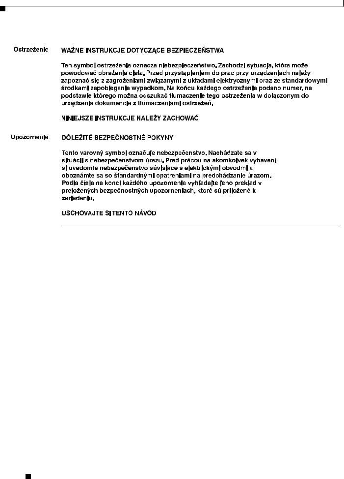
Finding the Product Serial Number
The access point serial number is on the bottom of the access point (refer to Figure 1).
Cisco Aironet 1550 Series Outdoor Mesh Access Point Hardware Installation Guide
|
xvi |
OL-24247-01 |
|
|
|
Running H/F 3
Running H/F 2
Figure 1 |
Location of Serial Number Label |
SN: NNNNNNNNN
231547, 781-00536-01 A0
SN: NNNNNNNNN
The access point serial number label contains the following information:
•Model number, such as AIR-CAP1552E-x-K9.
•Serial number, such as WCN0636279B (11 alphanumeric digits).
•Access point MAC address, for example 68BDABF54600 (12 hexadecimal digits). It is located under the serial number.
•Cable modem (CM) MAC address for cable configuration, such as 54D46F17377A (12 hexadecimal digits). The CM MAC address is only available on the access point cable configuration. It is located to the right of the MAC address.
You need your product serial number when requesting support from the Cisco Technical Assistance Center.
Obtaining Documentation, Support, and Security Guidelines
For information on obtaining documentation and support, providing documentation feedback, security guidelines, and recommended aliases and general Cisco documents, see the monthly What’s New in Cisco Product Documentation, which also lists all new and revised Cisco technical documentation, at:
http://www.cisco.com/en/US/docs/general/whatsnew/whatsnew.html
To view all new wireless documentation, click on Wireless.
Cisco Aironet 1550 Series Outdoor Mesh Access Point Hardware Installation Guide
|
OL-24247-01 |
xvii |
|

Running H/F 3
Running H/F 2
Cisco Aironet 1550 Series Outdoor Mesh Access Point Hardware Installation Guide
|
xviii |
OL-24247-01 |
|
|
|

C H A P T E R 1
Overview
The Cisco Aironet 1550 Series Outdoor Mesh Access Point (hereafter called the access point or AP) is a modularized wireless outdoor access point designed for use in a mesh network. The access point also supports wireless client access, point-to-point bridging, point-to-multipoint bridging, and point-to-multipoint mesh wireless connectivity.
About the 1552 Access Point
The 1552 access point supports two radios (2.4-GHz and 5-GHz) and provides client access without the need for a license. The 5-GHz radios are primarily used for backhaul operations to reach a wired network and the 2.4-GHz radio is used for wireless clients. Depending on the radio, the access point can support 1 to 300 Mb/s data rates (for specific data rates, refer to Appendix D, “Access Point Specifications”).
The 1552 access point supports the modularity of the 1520 series and allows flexibility in radio configuration. In addition to full interoperability with 802.11n clients, the 1552 access point interoperates with legacy clients and offers enhanced backhaul performance. The 1552 access point can also be configured with an integrated DOCSIS 3.0/Euro DOCSIS 3.0 cable modem.
The access point is a standalone unit that can be cable strand or tower mounted. The access point can also operate as a relay node for other access points not directly connected to a wired network. Intelligent wireless routing is provided by the patented Adaptive Wireless Path Protocol (AWPP). This enables each access point to identify its neighbors and intelligently choose the optimal path to the wired network by calculating the cost of each path in terms of signal strength and the number of hops required to get to a controller.
The access point is configured, monitored, and operated through a Cisco wireless LAN controller (hereafter called a controller) as described in the Cisco Wireless LAN Controller Configuration Guide. The Cisco Wireless Mesh Access Points, Design and Deployment Guide, Release 7.3 describes how to plan and initially configure the Cisco mesh network, which supports wireless point-to-point, point-to-multipoint, and mesh deployments. The controllers use a browser-based management system, a command-line interface (CLI), or the Cisco Prime Infrastructure (PI) network management system to manage the controller and the associated access points. The access point supports hardware-based advanced encryption standard (AES) encryption between wireless nodes to provide end-to-end security.
This chapter provides information on the following topics:
•Hardware Models, page 1-2
•Hardware Features, page 1-5
•Network Deployment Examples, page 1-25
Cisco Aironet 1550 Series Outdoor Mesh Access Point Hardware Installation Guide
|
OL-24247-01 |
1-1 |
|
|
|

Chapter 1 Overview
Hardware Models
Hardware Models
The model numbers (or part numbers) and configuration for the Cisco Aironet 1552 Outdoor Mesh Access Points are described in Table 1-1. A detailed list of components supported by each 1552 access point model is shown in Table 1-2.
The Cisco Aironet 1552 Series access points includes two additional models, 1552S and 1552H, that are specifically intended for deployment in hazardous locations. For information on these models, refer to the Cisco Aironet 1550 Series for Hazardous Locations Installation Guide.
For a detailed description of the declarations of conformity and regulatory information for the 1552 access points refer to Appendix B, “Declarations of Conformity and Regulatory Information.”
Table 1-1 1552 Access Point Model Numbers and Descriptions
Model (or part number) |
Configuration |
|
|
AIR-CAP1552E-x-K9 |
Two-radio (2.4 GHz and 5 GHz) modular version. |
|
This model supports three (3) external dual-band |
|
antenna ports. An optional Battery Backup Unit |
|
(BBU) and Small Form Factor Pluggable (SFP) |
|
fiber module can be ordered with the AP. |
|
Countries (regulatory domains) are represented |
|
by the variable x in the product model number. |
|
For specific regulatory domains supported by this |
|
model, refer to the product data sheet at: |
|
http://www.cisco.com/en/US/prod/collateral/wire |
|
less/ps5679/ps5861/product_data_sheet0900aecd |
|
80537b6a.html |
|
|
AIR-CAP1552EU-x-K9 |
Two-radio (2.4 GHz and 5 GHz) modular version. |
|
This model supports three (3) 2.4 GHz antenna |
|
ports and three (3) 5 GHz antenna ports. An |
|
optional Battery Backup Unit (BBU) and Small |
|
Form Factor Pluggable (SFP) fiber module can be |
|
ordered with the AP. Countries (regulatory |
|
domains) are represented by the variable x in the |
|
product model number. |
|
For specific regulatory domains supported by this |
|
model, refer to the product data sheet at: |
|
http://www.cisco.com/en/US/prod/collateral/wire |
|
less/ps5679/ps5861/product_data_sheet0900aecd |
|
80537b6a.html |
|
|
Cisco Aironet 1550 Series Outdoor Mesh Access Point Hardware Installation Guide
1-2 |
OL-24247-01 |
|
|
Chapter 1 Overview
Hardware Models
Table 1-1 1552 Access Point Model Numbers and Descriptions (continued)
Model (or part number) |
Configuration |
|
|
AIR-CAP1552C-x-K9 |
Two-radio (2.4 GHz and 5 GHz) version with |
|
DOCSIS 3.0 or Euro-DOCSIS 3.0 Cable Modem. |
|
This is a lightweight, low-profile AP. It supports |
|
cable modem backhaul and beamforming, and has |
|
an integrated 3-element array antenna. Countries |
|
(regulatory domains) are represented by the |
|
variable x in the product model number. |
|
For specific regulatory domains supported by this |
|
model, refer to the product data sheet at: |
|
http://www.cisco.com/en/US/prod/collateral/wire |
|
less/ps5679/ps5861/product_data_sheet0900aecd |
|
80537b6a.html |
|
|
AIR-CAP1552CU-x-K9 |
Two-radio (2.4 GHz and 5 GHz) version with |
|
DOCSIS 3.0 or Euro-DOCSIS 3.0 Cable Modem. |
|
This model supports three (3) 2.4 GHz antenna |
|
ports and three (3) 5 GHz antenna ports. This is a |
|
lightweight, low-profile AP. It supports cable |
|
modem backhaul and beamforming, and has an |
|
integrated 3-element array antenna. Countries |
|
(regulatory domains) are represented by the |
|
variable x in the product model number. |
|
For specific regulatory domains supported by this |
|
model, refer to the product data sheet at: |
|
http://www.cisco.com/en/US/prod/collateral/wire |
|
less/ps5679/ps5861/product_data_sheet0900aecd |
|
80537b6a.html |
|
|
AIR-CAP1552I-x-K9 |
Two-radio (2.4 GHz and 5 GHz) lightweight, |
|
low-profile version. This version consists of 1 AC |
|
power supply, Ethernet backhaul, and an |
|
integrated 3-element array antenna. Countries |
|
(regulatory domains) are represented by the |
|
variable x in the product model number. |
|
For specific regulatory domains supported by this |
|
model, refer to the product data sheet at: |
|
http://www.cisco.com/en/US/prod/collateral/wire |
|
less/ps5679/ps5861/product_data_sheet0900aecd |
|
80537b6a.html |
|
|
Cisco Aironet 1550 Series Outdoor Mesh Access Point Hardware Installation Guide
|
OL-24247-01 |
1-3 |
|
|
|

Chapter 1 Overview
Hardware Models
Table 1-2 |
Components of Each 1552 Access Point Model |
|
|
|||
|
|
|
|
|
|
|
|
|
1552E |
1552EU |
1552C |
1552CU |
1552I |
|
|
|
|
|
|
|
Antennas |
|
External |
External |
Integrated |
External |
Integrated |
|
|
|
|
|
|
|
Fiber SFP |
|
Yes |
Yes |
- |
- |
- |
|
|
|
|
|
|
|
PoE-Out Port1 |
|
Yes |
Yes |
- |
- |
- |
802.3af (for example, video) |
|
|
|
|
|
|
|
|
|
|
|
|
|
Cable Modem |
|
- |
- |
Yes |
Yes |
- |
DOCSIS 3.0 |
|
|
|
|
|
|
Euro DOCSIS 3.0 |
|
|
|
|
|
|
|
|
|
|
|
|
|
Battery Backup Option |
Yes |
Yes |
- |
- |
- |
|
|
|
|
|
|
|
|
Power Options |
|
AC, DC, |
AC, DC, |
40 to 90 VAC |
40 to 90 VAC |
AC, DC |
|
|
PoE2 |
PoE2 |
Power over |
Power over |
|
|
|
|
|
Cable, |
Cable, |
|
|
|
|
|
12 VDC |
12 VDC |
|
|
|
|
|
|
|
|
1.When a 1552E/EU is powered with PoE, the PoE-Out port is not active.
2, PoE-In is not 802.3af; it does not work with a PoE 802.3af-capable Ethernet switch. It requires the dedicated Power Injector (AIR-PWRINJ1500-2=).
Regulatory Domains
The “-x” in the 1552 model numbers represent the domain. For example, in AIR-CAP1552C-x-K9, the -x represents a regulatory domain for a specific country.
For specific regulatory domains supported by each 1552 access point model, refer to the Wireless LAN Compliance Status at:
http://www.cisco.com/en/US/prod/collateral/wireless/ps5679/ps5861/product_data_sheet0900aecd805 37b6a.html
To locate the 1552 access point models, click on 802.11abgn Mesh Access Points.
Cisco Aironet 1550 Series Outdoor Mesh Access Point Hardware Installation Guide
1-4 |
OL-24247-01 |
|
|

Chapter 1 Overview
Hardware Features
Hardware Features
This section describes the hardware features of the 1552 access point models. The following hardware features are described in this section:
•Connectors, page 1-5
•Antenna Port Locations, page 1-11
•Multiple Radio Operation, page 1-12
•Antenna Configurations, page 1-13
•Multiple Power Sources, page 1-21
•Cable Modem (POC), page 1-22
•Ethernet (PoE) Ports, page 1-22
•Fiber Option, page 1-23
•Metal Enclosure, page 1-24
•Optional Hardware, page 1-24
Connectors
Figure 1-1 through Figure 1-9 show the access point connectors for all models. Figure 1-10 and Figure 1-11 show the external antenna Type-N connectors.
Note The illustrations in this document show all available connections for the access point. Unused connections are capped with a connector plug to ensure the watertight integrity of the access point. Liquid-tight adapters are provided for connector openings, which can be installed before or after deploying the access point.
Cisco Aironet 1550 Series Outdoor Mesh Access Point Hardware Installation Guide
|
OL-24247-01 |
1-5 |
|
|
|
Chapter 1 Overview
Hardware Features
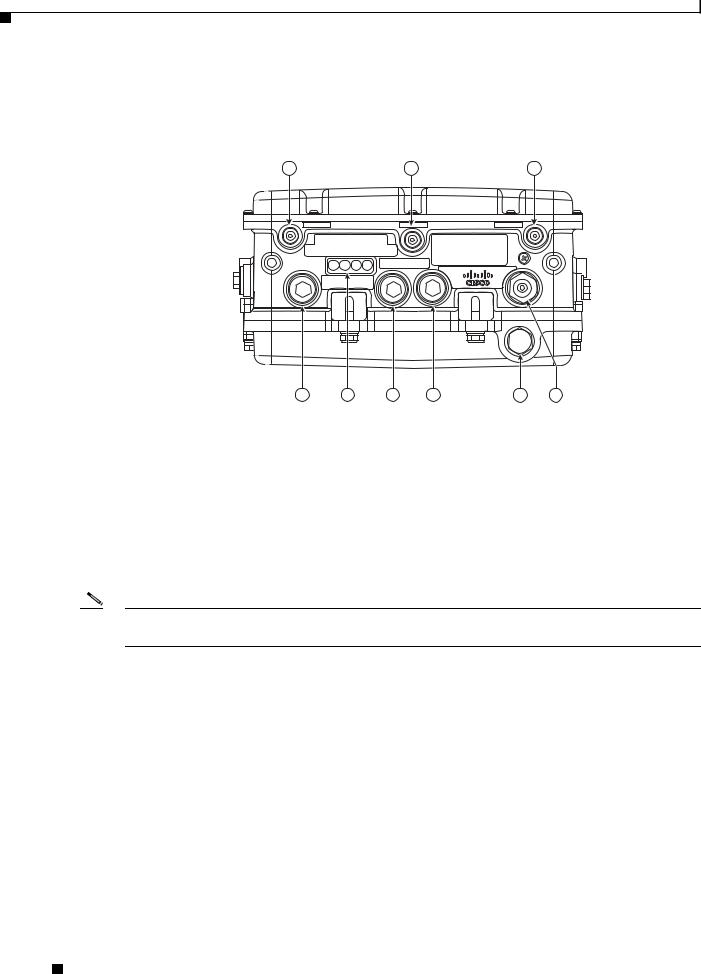
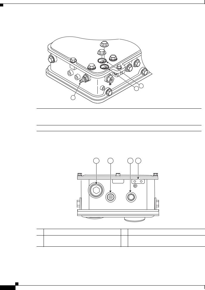
1552E/1552EU Connectors
Figure 1-1 |
Access Point Models AIR-CAP1552E-x-K9 and AIR-CAP1552EU-x-K9 Bottom |
|||||
|
Connectors |
|
|
|
|
|
|
1 |
|
|
2 |
|
3 |
|
|
4 |
5 |
|
6 |
|
|
|
|
|
|
|
282137 |
|
9 |
8 |
7 |
6 |
5 |
4 |
1 |
Antenna port 4 |
6 |
Fiber port |
|
|
|
|
2 |
Antenna port 5 |
7 |
PoE-out port |
|
|
|
|
3 |
Antenna port 6 |
8 |
LEDs (Status, Up Link, RF1, RF2) |
|
|
|
|
4 |
Auxiliary cable gland entry (1/2-NPT) for |
9 |
PoE-in port |
|
data cable (outdoor cat 5 STP cable) |
|
|
|
|
|
|
5 |
AC power entry port for model |
|
|
|
AIR-CAP1552E/EU-x-K9 only |
|
|
|
|
|
|
Note Antenna ports 1, 2, and 3 are not shown in Figure 1-1. These ports are located on the top of the access point.
Cisco Aironet 1550 Series Outdoor Mesh Access Point Hardware Installation Guide
1-6 |
OL-24247-01 |
|
|
Chapter 1 Overview
Hardware Features
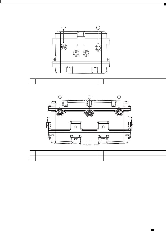
Figure 1-2 |
Console Port for Access Point Models AIR-CAP1552E-x-K9 and AIR-CAP1552EU-x-K9 |
|||
|
|
1 |
2 |
|
|
|
|
|
282138 |
1 |
Console port |
2 |
Not used |
|
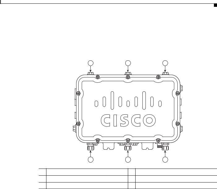
Figure 1-3 |
Access Point Model AIR-CAP1552EU-x-K9 Top Connectors |
|||
3 |
2 |
1 |
345675
1 Antenna port 1 |
3 Antenna port 3 |
2 Antenna port 2
Cisco Aironet 1550 Series Outdoor Mesh Access Point Hardware Installation Guide
|
OL-24247-01 |
1-7 |
|
|
|
Chapter 1 Overview
Hardware Features
1552I Connectors
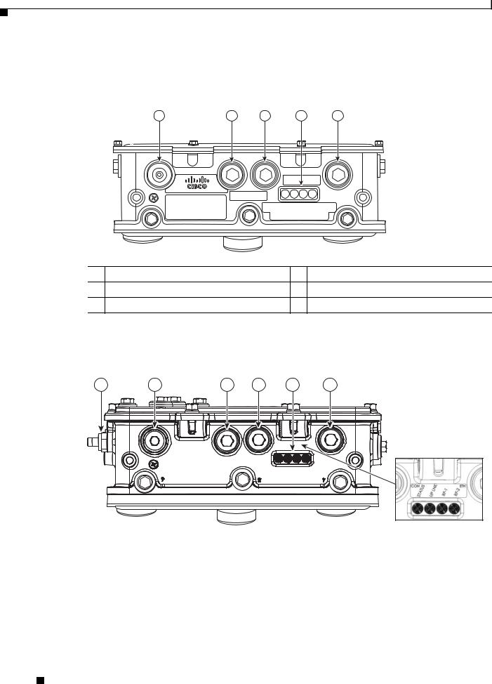
Figure 1-4
Access Point Model AIR-CAP1552I-x-K9 Bottom Connectors
1 |
2 |
3 |
4 |
5 |
|
|
|
282139 |
1 |
AC Connector |
4 |
LEDs (Status, Up Link, RF1, RF2) |
2 |
Not used |
5 |
Ethernet backhaul connector |
3 |
Console port |
|
|
1552C/1552CU Connectors
Figure 1-5 Access Point Model AIR-CAP1552C-x-K9 Bottom/Side Connectors
1 |
2 |
3 |
4 |
5 |
6 |
331577
1 |
F-Connector adapter (splitter) for cable POC |
4 |
Console port |
|
(optional) |
|
|
|
|
|
|
2 |
AC power connector (Not used) |
5 |
LEDs (Status, Up Link, RF1, RF2) |
|
|
|
|
3 |
Not used |
6 |
Not used |
|
|
|
|
Cisco Aironet 1550 Series Outdoor Mesh Access Point Hardware Installation Guide
1-8 |
OL-24247-01 |
|
|
Chapter 1 Overview
Hardware Features
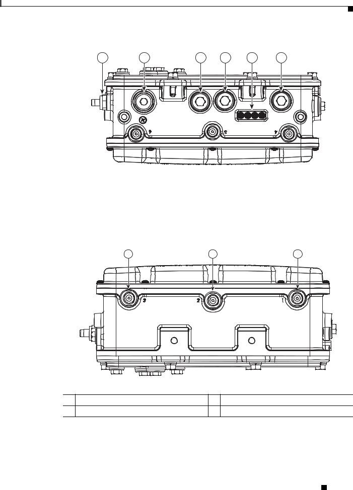
Figure 1-6 Access Point Model AIR-CAP-1552CU-x-K9 Bottom/Side Connectors
1 |
2 |
3 |
4 |
5 |
6 |
345703
1 |
F-Connector adapter (splitter) for cable POC |
4 |
Console port |
|
(optional) |
|
|
|
|
|
|
2 |
AC power connector (Not used) |
5 |
LEDs (Status, Up Link, RF1, RF2) |
|
|
|
|
3 |
Not used |
6 |
Not used |
|
|
|
|
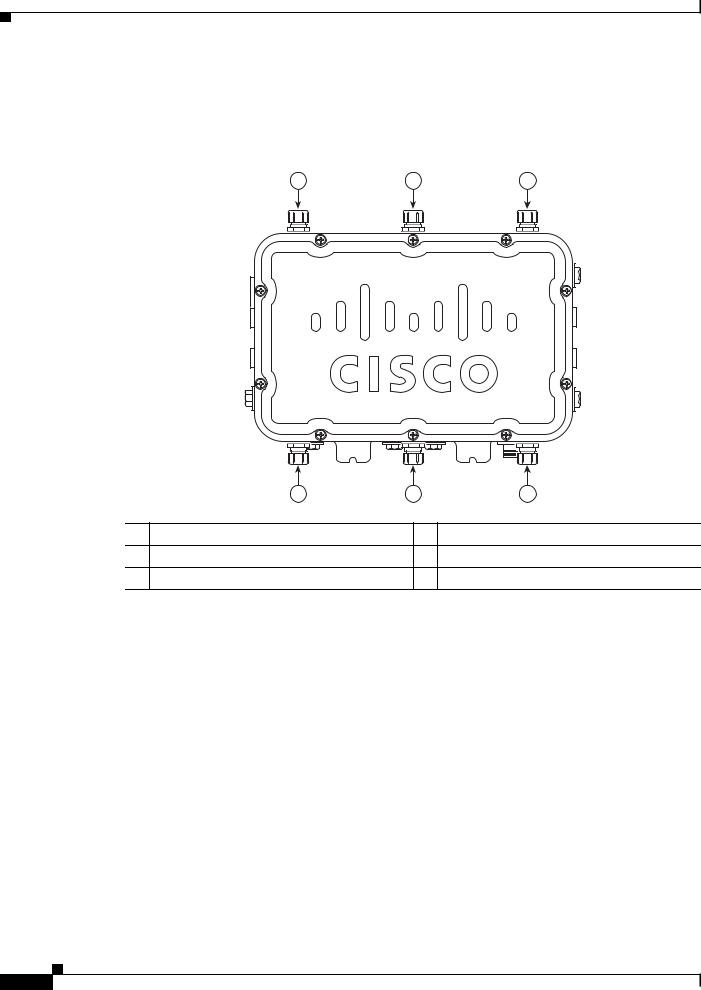
Figure 1-7 Access Point Model AIR-CAP1552CU-x-K9 Top Connectors
3 |
2 |
1 |
345837
1 Antenna port 1 |
3 Antenna port 3 |
2 Antenna port 2
Cisco Aironet 1550 Series Outdoor Mesh Access Point Hardware Installation Guide
|
OL-24247-01 |
1-9 |
|
|
|
Chapter 1 Overview
Hardware Features
Figure 1-8 F-Connector Adapter (Splitter) Components (AIR-CAP1552C-x-K9 and
AIR-CAP1552CU-x-K9)
255265
2
1
3
1 |
RF splitter attenuator (ATTN) |
3 |
F-Connector adapter (splitter) for cable POC |
|
|
|
(optional) |
|
|
|
|
2 |
RF splitter shunt (SHUNT)1 |
|
|
1 Shunt is a 20 amp fuse.
Connectors for All Models
Figure 1-9 Access Point DC Power Connector and Ground Lug (All Models)
1 |
2 |
3 |
4 |
|
|
|
282141 |
1 |
DC power port |
3 |
Bracket mounting nut |
2 |
Bracket mounting hole |
4 |
Ground lug location (connection for earth |
|
|
|
grounding (minimum VD 16 mm,6 AWG) |
|
Cisco Aironet 1550 Series Outdoor Mesh Access Point Hardware Installation Guide |
1-10 |
OL-24247-01 |
Chapter 1 Overview
Hardware Features
Antenna Port Locations
Figure 1-10 shows the antenna port locations for model AIR-CAP1552E-x-K9. The ports used depend on the optional antennas ordered.
Figure 1-10 External Antenna Port Locations for Access Point Models AIR-CAP1552E-x-K9
3 |
2 |
1 |
|
|
|
255247 |
|
6 |
5 |
4 |
1 |
Not used |
4 |
Antenna port 4 - Type N connector (with cap) |
2 |
Not used |
5 |
Antenna port 5 - Type N connector (with cap) |
3 |
Not used |
6 |
Antenna port 6 - Type N connector (with cap) |
|
|
Cisco Aironet 1550 Series Outdoor Mesh Access Point Hardware Installation Guide |
|
|
|
|
|
|
|||
|
OL-24247-01 |
|
|
1-11 |
|
|
|
|
|
||
Chapter 1 Overview
Hardware Features
Figure 1-11 shows the antenna port locations for models AIR-CAP1552CU-x-K9 and
AIR-CAP1552EU-x-K9. The ports used depend on the optional antennas ordered.
Figure 1-11 External Antenna Port Locations for Access Point Models AIR-CAP1552CU-x-K9 and AIR-CAP1552EU-x-K9
3 |
2 |
1 |
|
|
|
345674 |
|
6 |
5 |
4 |
1 |
Antenna port 3 - Type N connector (with cap) |
4 |
Antenna port 6 - Type N connector (with cap) |
2 |
Antenna port 2 - Type N connector (with cap) |
5 |
Antenna port 5 - Type N connector (with cap) |
3 |
Antenna port 1 - Type N connector (with cap) |
6 |
Antenna port 4 - Type N connector (with cap) |
Multiple Radio Operation
The 1552 access point supports simultaneous dual-radio operation using a 2.4-GHz 802.11b/g/n multiple input/multiple output (MIMO) radio and a 5-GHz 802.11a/n MIMO radio. The 2.4 GHz radio supports channels 1 to 11 in US, 1 to 13 in Europe, and 1 to 13 in Japan. It has two transmitters with a maximum total output power of 25 dBm for 802.11b/g/n operation. Output power is configurable to 5 levels. It has three receivers that enable maximum-ratio combining (MRC).
The 5-GHz radio operates in the UNII-2 band (5.25 – 5.35 GHz), UNII-2 Extended/ETSI band (5.47 – 5.725 GHz), upper ISM band (5.725 – 5.850 GHz), and the Extended India Band (5.85 – 5.875 GHz). It has two transmitters with a maximum total output power of 26 dBm for UNII-2 and Extended/ETSI bands. The total maximum output power for the upper ISM band is 28 dBm. Output power is configurable for 5 power levels in 3 dB steps. The three receivers enables maximum-ratio combining (MRC).
|
Cisco Aironet 1550 Series Outdoor Mesh Access Point Hardware Installation Guide |
1-12 |
OL-24247-01 |
Loading...