


2800
Table of contents
 Loading...
Corporate Headquarters:
Copyright © 2004 Cisco Systems, Inc. All rights reserved.
Cisco Systems, Inc., 170 West Tasman Drive, San Jose, CA 95134-1706 USA
Cisco 2800 Series Hardware Documents:
Introduction and Warnings
This introduction discusses the objectives, audience, organization, and conventions of these hardware
documents, and points to related documents that have information beyond the scope of these documents.
This preface contains the following sections:
• Objectives, page 1
• Audience, page 2
• Topics Covered by Hardware Documents, page 2
• Conventions, page 3
• Safety Warnings, page 4
• Related Documentation, page 9
• Cisco 90-Day Limited Hardware Warranty Terms, page 10
• Obtaining Documentation, page 11
• Documentation Feedback, page 12
• Obtaining Technical Assistance, page 12
• Obtaining Additional Publications and Information, page 14
Objectives
These hardware documents provide you with comprehensive hardware-related information about
Cisco 2800 series integrated services routers, including platform descriptions, safety information, site
preparation, chassis installation and interconnection, power up, initial configuration, troubleshooting,
interface card and module installation, and procedures for maintenance and upgrades.
These documents provide enough initial software configuration information to establish network
communication. For detailed software configuration information, refer to the Cisco 2800 series software
configuration documents and to the Cisco IOS configuration guides and command reference
publications. These publications are available online. See the “Obtaining Documentation” section on
page 11 for more information.

2
Cisco 2800 Series Hardware Documents: Introduction and Warnings
OL-5808-01
Audience
These documents describe several router platforms that are similar in functionality, but differ in the
number of interfaces supported. Some information provided may not apply to your particular router
model.
To access warranty, service, and support information, see the “Cisco 90-Day Limited Hardware Warranty
Terms” section on page 10.
Audience
This documentation is designed for the person installing, configuring, and maintaining the router, who
should be familiar with electronic circuitry and wiring practices and has experience as an electronic or
electromechanical technician. It identifies certain procedures that should be performed only by trained
and qualified personnel.
Topics Covered by Hardware Documents
Table 1 lists the topics covered by these hardware documents.
Table 1 Hardware Documentation for Cisco 2800 Series Routers
Topic Description
This document. Describes the features and warnings of
Cisco 2800 series routers.
Overview of Cisco 2800 Series Routers Describes the features and specifications of Cisco 2800
series routers.
Preinstallation Requirements and
Planning for Cisco 2800 Series Routers
Describes safety recommendations, site requirements, and
required tools and equipment, and includes an installation
checklist.
Port and Cable Information for
Cisco 2800 Series Routers
Provides information about cables needed to install your
Cisco 2800 series router.
Chassis Installation Procedures for
Cisco 2800 Series Routers
Describes how to install your Cisco 2800 series router on a
desktop, in a rack, or on a wall.
Cable Connection Procedures for
Cisco 2800 Series Routers
Describes how to connect your Cisco 2800 series router to
a power source and to networks and external devices.
Power Up and Initial Configuration
Procedures for Cisco 2800 Series Routers
Describes how to power up your Cisco 2800 series router
and perform an initial configuration to provide network
access.
Troubleshooting Cisco 2800 Series
Routers
Describes how to isolate problems, read LEDs, and
interpret error and recovery messages.
Installing Network Modules in
Cisco 2800 Series Routers
Contains links to the procedures for installing network
modules in external chassis slots.
Installing Interface Cards in Cisco 2800
Series Routers
Contains links to the procedures for installing the various
types of interface card in external chassis slots.

3
Cisco 2800 Series Hardware Documents: Introduction and Warnings
OL-5808-01
Conventions
Conventions
These documents use the conventions listed in Tab l e 2 to convey instructions and information:
Note Means reader take note. Notes contain helpful suggestions or references to material not covered in the
manual.
Timesaver Means the described action saves time. You can save time by performing the action described in the
paragraph.
Tip Means the following information will help you solve a problem. The tips information might not be
troubleshooting or even an action, but could be useful information, similar to a Timesaver.
Caution Means reader be careful. In this situation, you might do something that could result in equipment
damage or loss of data.
Installing and Upgrading Internal
Modules in Cisco 2800 Series Routers
Describes how to install or upgrade modules that are
located internally within the router, such as memory
modules, AIMs, PVDMs, and power supplies.
Removing and Installing CompactFlash
Memory Cards in Cisco 2800 Series
Routers
Describes hardware installation procedures that do not
require opening the chassis.
Table 1 Hardware Documentation for Cisco 2800 Series Routers (Continued)
Topic Description
Table 2 Document Conventions
Convention Description
boldface font Commands and keywords.
italic font Variables for which you supply values.
[ ] Optional keywords or arguments appear in square brackets.
{x | y | z} A choice of required keywords appears in braces separated by vertical bars. You must select one.
screen font
Examples of information displayed on the screen.
boldface screen
font
Examples of information you must enter.
< > Nonprinting characters, for example passwords, appear in angle brackets in contexts where italics are
not available.
[ ] Default responses to system prompts appear in square brackets.

4
Cisco 2800 Series Hardware Documents: Introduction and Warnings
OL-5808-01
Safety Warnings
Safety Warnings
Safety warnings appear throughout these publications in procedures that, if performed incorrectly, may
harm you. A warning symbol precedes each warning statement. To see translations of the warnings that
appear in these publications, refer to the Cisco 2800 Series Routers Regulatory Compliance and Safety
Information document that accompanied your router.
Warning Definition
Warning
IMPORTANT SAFETY INSTRUCTIONS
This warning symbol means danger. You are in a situation that could cause bodily injury. Before you
work on any equipment, be aware of the hazards involved with electrical circuitry and be familiar
with standard practices for preventing accidents. To see translations of the warnings that appear in
this publication, refer to the translated safety warnings that accompanied this device.
Statement
1071
SAVE THESE INSTRUCTIONS
Waarschuwing
BELANGRIJKE VEILIGHEIDSINSTRUCTIES
Dit waarschuwingssymbool betekent gevaar. U verkeert in een situatie die lichamelijk letsel kan
veroorzaken. Voordat u aan enige apparatuur gaat werken, dient u zich bewust te zijn van de bij
elektrische schakelingen betrokken risico's en dient u op de hoogte te zijn van de standaard
praktijken om ongelukken te voorkomen. Voor een vertaling van de waarschuwingen die in deze
publicatie verschijnen, dient u de vertaalde veiligheidswaarschuwingen te raadplegen die bij dit
apparaat worden geleverd.
Opmerking BEWAAR DEZE INSTRUCTIES.
Varoitus
TÄRKEITÄ TURVALLISUUTEEN LIITTYVIÄ OHJEITA
Tämä varoitusmerkki merkitsee vaaraa. Olet tilanteessa, joka voi johtaa ruumiinvammaan. Ennen
kuin työskentelet minkään laitteiston parissa, ota selvää sähkökytkentöihin liittyvistä vaaroista ja
tavanomaisista onnettomuuksien ehkäisykeinoista. Tässä asiakirjassa esitettyjen varoitusten
käännökset löydät laitteen mukana toimitetuista ohjeista.
Huomautus SÄILYTÄ NÄMÄ OHJEET
Attention
IMPORTANTES INFORMATIONS DE SÉCURITÉ
Ce symbole d'avertissement indique un danger. Vous vous trouvez dans une situation pouvant causer
des blessures ou des dommages corporels. Avant de travailler sur un équipement, soyez conscient
des dangers posés par les circuits électriques et familiarisez-vous avec les procédures couramment
utilisées pour éviter les accidents. Pour prendre connaissance des traductions d'avertissements
figurant dans cette publication, consultez les consignes de sécurité traduites qui accompagnent cet
appareil.
Remarque CONSERVEZ CES INFORMATIONS

5
Cisco 2800 Series Hardware Documents: Introduction and Warnings
OL-5808-01
Safety Warnings
Warnung
WICHTIGE SICHERHEITSANWEISUNGEN
Dieses Warnsymbol bedeutet Gefahr. Sie befinden sich in einer Situation, die zu einer
Körperverletzung führen könnte. Bevor Sie mit der Arbeit an irgendeinem Gerät beginnen, seien Sie
sich der mit elektrischen Stromkreisen verbundenen Gefahren und der Standardpraktiken zur
Vermeidung von Unfällen bewusst. Übersetzungen der in dieser Veröffentlichung enthaltenen
Warnhinweise sind im Lieferumfang des Geräts enthalten.
Hinweis BEWAHREN SIE DIESE SICHERHEITSANWEISUNGEN AUF
Avvertenza
IMPORTANTI ISTRUZIONI SULLA SICUREZZA
Questo simbolo di avvertenza indica un pericolo. La situazione potrebbe causare infortuni alle
persone. Prima di intervenire su qualsiasi apparecchiatura, occorre essere al corrente dei pericoli
relativi ai circuiti elettrici e conoscere le procedure standard per la prevenzione di incidenti. Per le
traduzioni delle avvertenze riportate in questo documento, vedere le avvertenze di sicurezza che
accompagnano questo dispositivo.
Nota CONSERVARE QUESTE ISTRUZIONI
Advarsel
VIKTIGE SIKKERHETSINSTRUKSJONER
Dette varselssymbolet betyr fare. Du befinner deg i en situasjon som kan forårsake personskade. Før
du utfører arbeid med utstyret, bør du være oppmerksom på farene som er forbundet med elektriske
kretssystemer, og du bør være kjent med vanlig praksis for å unngå ulykker. For å se oversettelser av
advarslene i denne publikasjonen, se de oversatte sikkerhetsvarslene som følger med denne
enheten.
Merk TA VARE PÅ DISSE INSTRUKSJONENE
Aviso
INSTRUÇÕES IMPORTANTES DE SEGURANÇA
Este símbolo de aviso significa perigo. O utilizador encontra-se numa situação que poderá ser
causadora de lesões corporais. Antes de iniciar a utilização de qualquer equipamento, tenha em
atenção os perigos envolvidos no manuseamento de circuitos eléctricos e familiarize-se com as
práticas habituais de prevenção de acidentes. Para ver traduções dos avisos incluídos nesta
publicação, consulte os avisos de segurança traduzidos que acompanham este dispositivo.
Nota GUARDE ESTAS INSTRUÇÕES
¡Advertencia!
INSTRUCCIONES IMPORTANTES DE SEGURIDAD
Este símbolo de aviso indica peligro. Existe riesgo para su integridad física. Antes de manipular
cualquier equipo, considere los riesgos de la corriente eléctrica y familiarícese con los
procedimientos estándar de prevención de accidentes. Vea las traducciones de las advertencias
que acompañan a este dispositivo.
Nota GUARDE ESTAS INSTRUCCIONES

6
Cisco 2800 Series Hardware Documents: Introduction and Warnings
OL-5808-01
Safety Warnings
Varning!
VIKTIGA SÄKERHETSANVISNINGAR
Denna varningssignal signalerar fara. Du befinner dig i en situation som kan leda till personskada.
Innan du utför arbete på någon utrustning måste du vara medveten om farorna med elkretsar och
känna till vanliga förfaranden för att förebygga olyckor. Se översättningarna av de
varningsmeddelanden som finns i denna publikation, och se de översatta säkerhetsvarningarna som
medföljer denna anordning.
OBS! SPARA DESSA ANVISNINGAR

7
Cisco 2800 Series Hardware Documents: Introduction and Warnings
OL-5808-01
Safety Warnings
Aviso
INSTRUÇÕES IMPORTANTES DE SEGURANÇA
Este símbolo de aviso significa perigo. Você se encontra em uma situação em que há risco de lesões
corporais. Antes de trabalhar com qualquer equipamento, esteja ciente dos riscos que envolvem os
circuitos elétricos e familiarize-se com as práticas padrão de prevenção de acidentes. Use o
número da declaração fornecido ao final de cada aviso para localizar sua tradução nos avisos de
segurança traduzidos que acompanham o dispositivo.
GUARDE ESTAS INSTRUÇÕES
Advarsel
VIGTIGE SIKKERHEDSANVISNINGER
Dette advarselssymbol betyder fare. Du befinder dig i en situation med risiko for
legemesbeskadigelse. Før du begynder arbejde på udstyr, skal du være opmærksom på de
involverede risici, der er ved elektriske kredsløb, og du skal sætte dig ind i standardprocedurer til
undgåelse af ulykker. Brug erklæringsnummeret efter hver advarsel for at finde oversættelsen i de
oversatte advarsler, der fulgte med denne enhed.
GEM DISSE ANVISNINGER
8
Cisco 2800 Series Hardware Documents: Introduction and Warnings
OL-5808-01
Safety Warnings
9
Cisco 2800 Series Hardware Documents: Introduction and Warnings
OL-5808-01
Related Documentation
Related Documentation
The Cisco IOS software running your Cisco 2800 series router includes extensive features and
functionality. For information that is beyond the scope of these documents, or for additional information,
use the following resources:
Timesaver Make sure that you have access to the documents listed in Table 3. Some of these documents are
available in print, and all are on the World Wide Web. If you need to order printed documents, see the
“Obtaining Documentation” section on page 11.

10
Cisco 2800 Series Hardware Documents: Introduction and Warnings
OL-5808-01
Cisco 90-Day Limited Hardware Warranty Terms
Cisco 90-Day Limited Hardware Warranty Terms
There are special terms applicable to your hardware warranty and various services that you can use
during the warranty period. Your formal Warranty Statement, including the warranties and license
agreements applicable to Cisco software, is available on Cisco.com. Follow these steps to access and
download the Cisco Information Packet and your warranty and license agreements from Cisco.com.
1. Launch your browser, and go to this URL:
http://www.cisco.com/univercd/cc/td/doc/es_inpck/cetrans.htm
The Warranties and License Agreements page appears.
2. To read the Cisco Information Packet, follow these steps:
a. Click the Information Packet Number field, and make sure that the part number
78-5235-03A0 is highlighted.
b. Select the language in which you would like to read the document.
c. Click Go.
The Cisco Limited Warranty and Software License page from the Information Packet appears.
d. Read the document online, or click the PDF icon to download and print the document in Adobe
Portable Document Format (PDF).
Table 3 Related and Referenced Documents
Cisco Product Document Title
Cisco 2800 series routers Cisco 2800 Series Routers Quick Start Guide
Software configuration documentation for Cisco 2800 series routers
Cisco 2800 Series and Cisco 3800 Series Routers Regulatory Compliance
and Safety Information
Cisco 2800 Series Cards and Modules
Cisco Modular Access Router Cable Specifications
Cisco RPS-675 Redundant Power System Hardware Installation Guide
Quick Start Guide: Network Modules for Cisco 2600 Series, Cisco 2800
Series, Cisco 3600 Series, Cisco 3700 Series Routers, and Cisco 3800
Series Routers
Cisco Network Modules Hardware Installation Guide
Quick Start Guide: Interface Cards for Cisco 1600, 1700, 1800, 2600,
2800, 3600, 3700, and 3800 Series Routers
Cisco Interface Cards Installation Guide
Network management
system
Network management software documentation
Cisco IOS software Cisco IOS software documentation, all releases. Refer to the
documentation for the Cisco IOS software release installed on your
router.

11
Cisco 2800 Series Hardware Documents: Introduction and Warnings
OL-5808-01
Obtaining Documentation
Note You must have Adobe Acrobat Reader to view and print PDF files. You can download
the reader from Adobe’s website: http://www.adobe.com
3. To read translated and localized warranty information about your product, follow these steps:
a. Enter this part number in the Warranty Document Number field:
78-5236-01C0
b. Select the language in which you would like to read the document.
c. Click Go.
The Cisco warranty page appears.
d. Review the document online, or click the PDF icon to download and print the document in
Adobe Portable Document Format (PDF).
You can also contact the Cisco service and support website for assistance:
http://www.cisco.com/public/Support_root.shtml.
Duration of Hardware Warranty
Ninety (90) days.
Replacement, Repair, or Refund Policy for Hardware
Cisco or its service center will use commercially reasonable efforts to ship a replacement part within ten
(10) working days after receipt of a Return Materials Authorization (RMA) request. Actual delivery
times can vary, depending on the customer location.
Cisco reserves the right to refund the purchase price as its exclusive warranty remedy.
To Receive a Return Materials Authorization (RMA) Number
Contact the company from whom you purchased the product. If you purchased the product directly from
Cisco, contact your Cisco Sales and Service Representative.
Complete the information below, and keep it for reference:
Obtaining Documentation
Cisco documentation and additional literature are available on Cisco.com. Cisco also provides several
ways to obtain technical assistance and other technical resources. These sections explain how to obtain
technical information from Cisco Systems.
Company product purchased from
Company telephone number
Product model number
Product serial number
Maintenance contract number

12
Cisco 2800 Series Hardware Documents: Introduction and Warnings
OL-5808-01
Documentation Feedback
Cisco.com
You can access the most current Cisco documentation at this URL:
http://www.cisco.com/univercd/home/home.htm
You can access the Cisco website at this URL:
http://www.cisco.com
You can access international Cisco websites at this URL:
http://www.cisco.com/public/countries_languages.shtml
Ordering Documentation
You can find instructions for ordering documentation at this URL:
http://www.cisco.com/univercd/cc/td/doc/es_inpck/pdi.htm
You can order Cisco documentation in these ways:
• Registered Cisco.com users (Cisco direct customers) can order Cisco product documentation from
the Ordering tool:
http://www.cisco.com/en/US/partner/ordering/index.shtml
• Nonregistered Cisco.com users can order documentation through a local account representative by
calling Cisco Systems Corporate Headquarters (California, USA) at 408 526-7208 or, elsewhere in
North America, by calling 800 553-NETS (6387).
Documentation Feedback
You can send comments about technical documentation to bug-doc@cisco.com.
You can submit comments by using the response card (if present) behind the front cover of your
document or by writing to the following address:
Cisco Systems
Attn: Customer Document Ordering
170 West Tasman Drive
San Jose, CA 95134-9883
We appreciate your comments.
Obtaining Technical Assistance
For all customers, partners, resellers, and distributors who hold valid Cisco service contracts, Cisco
Technical Support provides 24-hour-a-day, award-winning technical assistance. The Cisco Technical
Support Website on Cisco.com features extensive online support resources. In addition, Cisco Technical
Assistance Center (TAC) engineers provide telephone support. If you do not hold a valid Cisco service
contract, contact your reseller.

13
Cisco 2800 Series Hardware Documents: Introduction and Warnings
OL-5808-01
Obtaining Technical Assistance
Cisco Technical Support Website
The Cisco Technical Support Website provides online documents and tools for troubleshooting and
resolving technical issues with Cisco products and technologies. The website is available 24 hours a day,
365 days a year at this URL:
http://www.cisco.com/techsupport
Access to all tools on the Cisco Technical Support Website requires a Cisco.com user ID and password.
If you have a valid service contract but do not have a user ID or password, you can register at this URL:
http://tools.cisco.com/RPF/register/register.do
Submitting a Service Request
Using the online TAC Service Request Tool is the fastest way to open S3 and S4 service requests. (S3
and S4 service requests are those in which your network is minimally impaired or for which you require
product information.) After you describe your situation, the TAC Service Request Tool automatically
provides recommended solutions. If your issue is not resolved using the recommended resources, your
service request will be assigned to a Cisco TAC engineer. The TAC Service Request Tool is located at
this URL:
http://www.cisco.com/techsupport/servicerequest
For S1 or S2 service requests or if you do not have Internet access, contact the Cisco TAC by telephone.
(S1 or S2 service requests are those in which your production network is down or severely degraded.)
Cisco TAC engineers are assigned immediately to S1 and S2 service requests to help keep your business
operations running smoothly.
To open a service request by telephone, use one of the following numbers:
Asia-Pacific: +61 2 8446 7411 (Australia: 1 800 805 227)
EMEA: +32 2 704 55 55
USA: 1 800 553 2447
For a complete list of Cisco TAC contacts, go to this URL:
http://www.cisco.com/techsupport/contacts
Definitions of Service Request Severity
To ensure that all service requests are reported in a standard format, Cisco has established severity
definitions.
Severity 1 (S1)—Your network is “down,” or there is a critical impact to your business operations. You
and Cisco will commit all necessary resources around the clock to resolve the situation.
Severity 2 (S2)—Operation of an existing network is severely degraded, or significant aspects of your
business operation are negatively affected by inadequate performance of Cisco products. You and Cisco
will commit full-time resources during normal business hours to resolve the situation.
Severity 3 (S3)—Operational performance of your network is impaired, but most business operations
remain functional. You and Cisco will commit resources during normal business hours to restore service
to satisfactory levels.
Severity 4 (S4)—You require information or assistance with Cisco product capabilities, installation, or
configuration. There is little or no effect on your business operations.

14
Cisco 2800 Series Hardware Documents: Introduction and Warnings
OL-5808-01
Obtaining Additional Publications and Information
Obtaining Additional Publications and Information
Information about Cisco products, technologies, and network solutions is available from various online
and printed sources.
• Cisco Marketplace provides a variety of Cisco books, reference guides, and logo merchandise. Visit
Cisco Marketplace, the company store, at this URL:
http://www.cisco.com/go/marketplace/
• The Cisco Product Catalog describes the networking products offered by Cisco Systems, as well as
ordering and customer support services. Access the Cisco Product Catalog at this URL:
http://cisco.com/univercd/cc/td/doc/pcat/
• Cisco Press publishes a wide range of general networking, training and certification titles. Both new
and experienced users will benefit from these publications. For current Cisco Press titles and other
information, go to Cisco Press at this URL:
http://www.ciscopress.com
• Pack et magazine is the Cisco Systems technical user magazine for maximizing Internet and
networking investments. Each quarter, Packet delivers coverage of the latest industry trends,
technology breakthroughs, and Cisco products and solutions, as well as network deployment and
troubleshooting tips, configuration examples, customer case studies, certification and training
information, and links to scores of in-depth online resources. You can access Packet magazine at this
URL:
http://www.cisco.com/packet
• iQ Magazine is the quarterly publication from Cisco Systems designed to help growing companies
learn how they can use technology to increase revenue, streamline their business, and expand
services. The publication identifies the challenges facing these companies and the technologies to
help solve them, using real-world case studies and business strategies to help readers make sound
technology investment decisions. You can access iQ Magazine at this URL:
http://www.cisco.com/go/iqmagazine
• Internet Protocol Journal is a quarterly journal published by Cisco Systems for engineering
professionals involved in designing, developing, and operating public and private internets and
intranets. You can access the Internet Protocol Journal at this URL:
http://www.cisco.com/ipj
• World-class networking training is available from Cisco. You can view current offerings at
this URL:
http://www.cisco.com/en/US/learning/index.html. This document is to be used in conjunction with
the documents listed in the “Related Documentation” section.

15
Cisco 2800 Series Hardware Documents: Introduction and Warnings
OL-5808-01
Obtaining Additional Publications and Information

16
Cisco 2800 Series Hardware Documents: Introduction and Warnings
OL-5808-01
Obtaining Additional Publications and Information
Copyright © 2004 Cisco Systems, Inc. All rights reserved.
CCVP, the Cisco Logo, and the Cisco Square Bridge logo are trademarks of Cisco Systems, Inc.; Changing the Way We Work, Live, Play, and Learn is a
service mark of Cisco Systems, Inc.; and Access Registrar, Aironet, BPX, Catalyst, CCDA, CCDP, CCIE, CCIP, CCNA, CCNP, CCSP, Cisco, the Cisco
Certified Internetwork Expert logo, Cisco IOS, Cisco Press, Cisco Systems, Cisco Systems Capital, the Cisco Systems logo, Cisco Unity,
Enterprise/Solver, EtherChannel, EtherFast, EtherSwitch, Fast Step, Follow Me Browsing, FormShare, GigaDrive, GigaStack, HomeLink, Interne
t
Quotient, IOS, iPhone, IP/TV, iQ Expertise, the iQ logo, iQ Net Readiness Scorecard, iQuick Study, LightStream, Linksys, MeetingPlace, MGX,
Networking Academy, Network Registrar, Pack e t, PIX, ProConnect, RateMUX, ScriptShare, SlideCast, SMARTnet, StackWise, The Fastest Way to
Increase Your Internet Quotient, and TransPath are registered trademarks of Cisco Systems, Inc. and/or its affiliates in the United States and certain othe
r
countries.
All other trademarks mentioned in this document or Website are the property of their respective owners. The use of the word partner does not imply a
partnership relationship between Cisco and any other company. (0612R)
Corporate Headquarters:
Copyright © 2004 Cisco Systems, Inc. All rights reserved.
Cisco Systems, Inc., 170 West Tasman Drive, San Jose, CA 95134-1706 USA
Overview of Cisco 2800 Series Routers
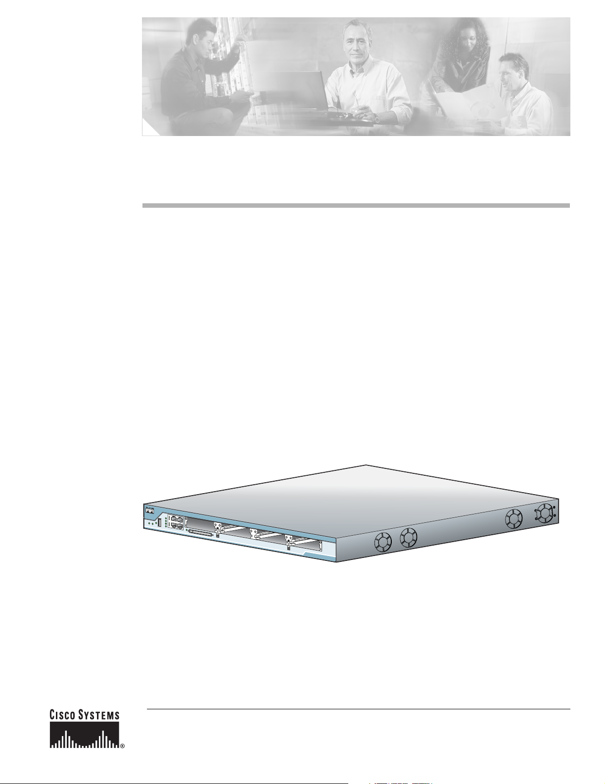
The Cisco 2800 series of integrated services routers offers secure, wire-speed delivery of concurrent
data, voice, and video services. The modular design of the Cisco 2800 series routers provides maximum
flexibility, allowing you to configure your router to meet evolving needs. The Cisco 2800 series routers
incorporate data, security, and voice services in a single system for fast, scalable delivery of crucial
business applications. The routers offer features such as hardware-based VPN encryption acceleration,
intrusion-protection and firewall functions, and optional integrated call processing and voice mail. The
routers offer a wide variety of network modules and interfaces, voice digital signal processor (DSP)
slots, high-density interfaces for a wide range of connectivity requirements, and sufficient performance
and slot density for future network expansion requirements and advanced applications.
The Cisco 2800 series consists of four versions. The Cisco 2801 routers and Cisco 2811 routers are one
rack unit in height and have two 10/100 LAN ports. The more powerful Cisco 2821 routers and
Cisco 2851 routers are two rack units in height and have two 10/100/1000 LAN ports. The higher-end
router platforms of the Cisco 2800 series offer increased performance, increased slot density including
network module slots ad extension voice module slots and increased inline power output.
Figure 1, Figure 2, and Figure 3 show front views of the Cisco 2800 series routers.
Figure 1 Front View of a Cisco 2801 Router
95817

2
Overview of Cisco 2800 Series Routers
OL-5783-01
Hardware Features
Figure 2 Front View of a Cisco 2811 Router
Figure 3 Front View of a Cisco 2821 or Cisco 2851 Router
This chapter describes the features and specifications of the routers and includes the following sections:
• Hardware Features, page 2
• Chassis Views, page 10
• Interface Numbering, page 16
• Specifications, page 18
• Regulatory Compliance, page 25
Hardware Features
This section describes the basic features of Cisco 2800 series routers, including product identification,
built-in interfaces, modules, memory, LED indicators, chassis ventilation, and the internal clock.
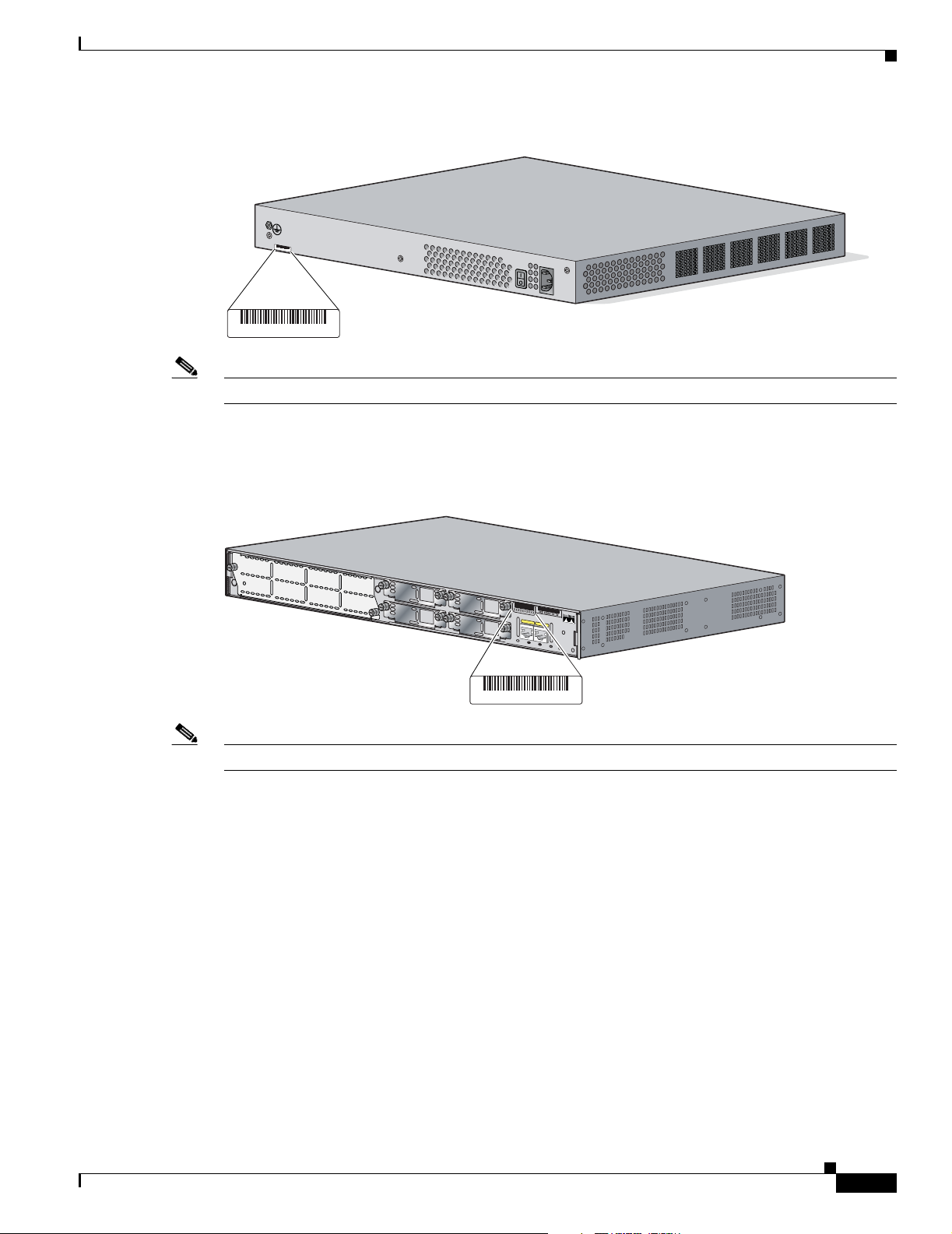
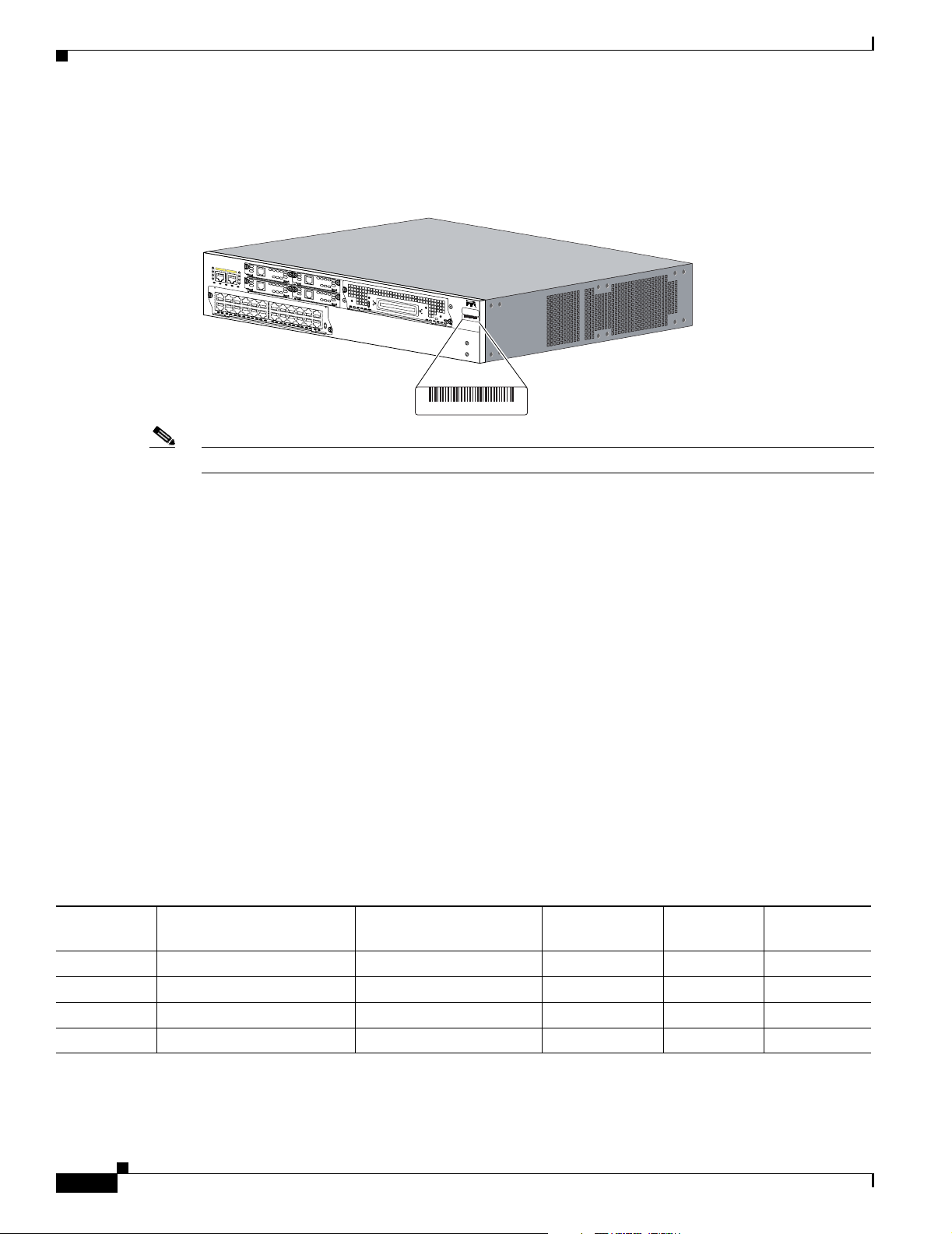
Product Serial Number Location
The serial number label for Cisco 2801 routers is located on the rear of the chassis, along the bottom
edge near the lower left corner. (See Figure 4.)
95902
Do Not Remove During Network O
peration
COMPACT FLASH
CONSOLE
OPTIO
NAL RPS INPUT
12V 11A
AUX
SYS
PW
R
AUX/
PWR
SYS
ACT
CF
-48V 4A
100-240 V~ 4A
50/60 Hz
0
1
95903
Do Not Remove During Network Operation
COMPACT FLASH
CONSOLE
AUX
SYS
PWR
AUX/
PWR
SYS
ACT
CF
0
1
O
P
T
IO
N
A
L
R
P
S
IN
P
U
T
1
2
V
1
1
A
-4
8
V
4
A
100-240 V
~ 4A
50/60 H
z
3
Overview of Cisco 2800 Series Routers
OL-5783-01
Hardware Features
Figure 4 Serial Number Location on the Cisco 2801 Router
Note The serial number for Cisco 2801 routers is 11 characters long.
The serial number label for Cisco 2811 routers is located on the rear of the chassis, near the top right
corner, to the left of the CLEI label. (See Figure 5.)
Figure 5 Serial Number Location on the Cisco 2811 Router
Note The serial number for Cisco 2811 routers is 11 characters long.
117342 781-00286-01
SN: AAANNNNXXXX
SN: AAANNNNX
XXX
103962 781-00287-01
A
=
A
C
T
F
E
0
/1
P
V
D
M
1
P
V
D
M
0
A
IM
1
A
IM
0
F
E
0
/0
S
=
S
P
E
E
D
A
=
F
D
X
A
=
L
IN
K
A
F
S
L
A
F
S
L
S
L
O
T
2
S
L
O
T
0
S
L
O
T
3
S
L
O
T
1
E
N
M
0
SN: AAANNNNXXXX
4
Overview of Cisco 2800 Series Routers
OL-5783-01
Hardware Features
The serial number label for Cisco 2821 and Cisco 2851 routers is located on the rear of the chassis, near
the top right corner, below the CLEI label. (See Figure 6.)
Figure 6 Serial Number Location on the Cisco 2821 and Cisco 2851 Routers
Note The serial number for Cisco 2821 and Cisco 2851 routers is 11 characters long.
Cisco Product Identification Tool
The Cisco Product Identification (CPI) tool provides detailed illustrations and descriptions showing
where to locate serial number labels on Cisco products. It includes the following features:
• A search option that allows browsing for models using a tree-structured product hierarchy
• A search field on the final results page making it easier to look up multiple products
• End-of-sale products are clearly identified in results lists
The tool streamlines the process of locating serial number labels and identifying products. Serial number
information expedites the entitlement process and is important for access to support services.
The Cisco Product Identification tool can be accessed at the following URL:
http://tools.cisco.com/Support/CPI/index.do
Built-in Interfaces
Table 1 summarizes the interface ports built into the chassis.
103963 781-00288-01
A= ACT
FE 0/1
PVDM2
PVDM1
PVD
M0
AIM1
AIM0
FE 0/0
S= SP
EED
A= FDX
A= LINK
A
F
S
L
A
F
S
L
SN: AAANNNNXXXX
SN: AAANNNNXXXX
Table 1 Summary of Cisco 2800 Series Built-In Interfaces
Model
100BASE-T Fast Ethernet (FE)
Ports (RJ-45)
1000BASE-T Gigabit
Ethernet (GE) Ports (RJ-45)
Universal Serial
Bus (USB) Ports
Console Port
(RJ-45)
Auxiliary Port
(RJ-45)
Cisco 2801 2 — 1 1 1
Cisco 2811 2 — 2 1 1
Cisco 2821 — 2 2 1 1
Cisco 2851 — 2 2 1 1

5
Overview of Cisco 2800 Series Routers
OL-5783-01
Hardware Features
Removable and Interchangeable Modules
Table 2 summarizes the optional modules that can be installed in the router to provide specific
capabilities. The network modules, extension voice modules, and interface cards fit into slots, located
on the front of the chassis on the Cisco 2801 router, and on the rear of the chassis on the Cisco 2811,
Cisco 2821, and Cisco 2851 routers; they can be removed and installed without opening the chassis.
Advanced integration modules (AIMs), expansion DRAM memory modules (DIMMs), and packet voice
data modules (PVDMs) plug into connectors inside the chassis; they can be removed and installed only
by opening the chassis.
Table 2 Summary of Cisco 2800 Series Removable and Interchangeable Modules
Router Model
External Modules (In chassis slots) Internal Modules
Network Modules
High-Speed WAN
Interface Cards (HWICs)
Extension Voice
Modules
(EVMs)
Advanced
Integration
Modules (AIMs)
Packet Voice
Data Modules
(PVDMs)
1
1. Cisco 2800 series routers use PVDM II modules that are not compatible with Cisco 2600 series routers.
Cisco 2801 — 2 single-wide (HWIC) or
2 double-wide (HWIC-D)
1 WIC/VWIC/VIC slot
1 VWIC/VIC (voice-only)
—22
Cisco 2811 1 network module (NM) or
1 network module enhanced
(NME)
4 single-wide (HWIC) or
2 double-wide (HWIC-D)
—22
Cisco 2821 1 network module (NM) or
1 network module enhanced
(NME) or
1 network module enhanced
extended (NME-X)
4 single-wide (HWIC) or
2 double-wide (HWIC-D)
123
Cisco 2851 1 network module (NM) or
1 network module enhanced
(NME) or
1 network module enhanced
extended (NME-X) or
1 network module
double-wide (NMD) or
1 network module enhanced
extended double-wide
(NME-XD)
4 single-wide (HWIC) or
2 double-wide (HWIC-D)
123

6
Overview of Cisco 2800 Series Routers
OL-5783-01
Hardware Features
Memory
Cisco 2800 series routers contain the following types of memory:
• DRAM—Stores the running configuration and routing tables and is used for packet buffering by the
network interfaces. Cisco IOS software executes from DRAM memory.
• Boot/NVRAM—Internal flash memory. Stores the bootstrap program (ROM monitor), the
configuration register, and the startup configuration.
• Flash memory—External flash memory. Stores the operating system software image.
Table 3 summarizes the memory options for Cisco 2800 series routers. The default memory numbers for
RAM represent the minimum usable memory. You can install additional RAM in multiples of the default
amount, up to the maximum amount.
Table 3 Router Memory Specifications
Router
Platform DRAM Boot/NVRAM Flash Memory
Cisco 2801 Type—SDRAM DIMM
DIMM sizes—64 MB, 128 MB, 256 MB
DIMM expansion slots—1
1
Default onboard memory—128 MB
Maximum memory—384 MB
1. Cisco 2801 routers have 128 MB of SDRAM soldered onto the system board. You can install a DIMM into the expansion slot
to increase memory to the maximum of 384 MB.
Internal 4-MB
flash memory
External CompactFlash
memory cards of the
following optional
sizes:
• 64 MB (default)
• 128 MB
Cisco 2811 Type—ECC DDR (error-correcting code,
double data rate) SDRAM DIMM
DIMM sizes—256 MB, 512 MB
DIMM slots—2
Default onboard memory— none
Default memory—256 MB
Maximum memory—768 MB
2
2. Cisco 2811 routers can accept one 256 MB and one 512 MB DIMM to provide 768 MB of usable memory.
Internal 2-MB
flash memory
External CompactFlash
memory cards of the
following optional
sizes:
• 64 MB (default)
• 128 MB
• 256 MB
Cisco 2821 Type—ECC DDR (error-correcting code,
double data rate) DRAM DIMM
DIMM sizes—256 MB, 512 MB
DIMM slots—2
Default onboard memory— none
Default memory—256 MB
Maximum memory—1024 MB
3
3. Cisco 2851 routers can accept two 512 MB DIMMs to provide 1024 MB of usable memory.
Cisco 2851

7
Overview of Cisco 2800 Series Routers
OL-5783-01
Hardware Features
Power
Table 4 summarizes the power options for Cisco 2800 series routers. Cisco 2801 routers are equipped
for operation using AC power only. Cisco 2811, Cisco 2821, and Cisco 2851 routers can be equipped for
operation using either AC or DC input power by installation of the appropriate chassis power supply. IP
phone power is supported if the appropriate AC-input chassis power supply is installed.
LED Indicators
Table 5 and Table 6 summarize the LED indicators that are located in the router bezel or chassis, but not
in removable modules or interface cards.
Table 4 Summary of Cisco 2800 Series Power Options
Router Model Power Option Input IP Phone Power Output
Cisco 2801 AC input without IP phone power
output
100 - 240 VAC, 2 A None
AC input with IP phone power
output
100 - 240 VAC, 5 A –48 VDC, 120 W
Cisco 2811 AC input without IP phone power
output
100 - 240 VAC, 2 A None
AC input with IP phone power
output
100 - 240 VAC, 4 A –48 VDC, 160 W
DC input without IP phone power
output
24 - 60 VDC, 8 A None
Cisco 2821 AC input without IP phone power
output
100 - 240 VAC, 3 A None
AC input with IP phone power
output
100 - 240 VAC, 8 A –48 VDC, 240 W
DC input without IP phone power
output
24 - 60 VDC, 12 A None
Cisco 2851 AC input without IP phone power
output
100 - 240 VAC, 3 A None
AC input with IP phone power
output
100 - 240 VAC, 8 A –48 VDC, 360 W
DC input without IP phone power
output
24 - 60 VDC, 12 A None
Cisco 2811,
Cisco 2821, and
Cisco 2851
Backup power for AC- or
DC-powered routers:
Cisco Redundant Power System
(RPS-675)
100 VAC, 10 A,
or 240 VAC, 6 A
The Cisco RPS provides IP phone power
only if the chassis power supply supports
IP phone power.
With Cisco 2811: –48 VDC, 160 W
With Cisco 2821: –48 VDC, 240 W
With Cisco 2851: –48 VDC, 360 W

8
Overview of Cisco 2800 Series Routers
OL-5783-01
Hardware Features
To see descriptions of LEDs in removable modules and interface cards, refer to the applicable
documentation for those products: the Cisco Network Modules Hardware Installation Guide or the Cisco
Interface Cards Installation Guide.
For LED troubleshooting information, including possible trouble causes and corrective actions, see
Table 1 in the “Troubleshooting Cisco 2800 Series Routers” document.
Table 5 Summary of Cisco 2801 Series LED Indicators
LED Color Description Location
SYS PWR Green Router has successfully booted up and the
software is functional. This LED blinks while
booting or in the ROM monitor.
Front
SYS ACT Green Blinking when any packets are transmitted or received
on any WAN or LAN or system is monitoring internal
activities.
Front
CF Green On when flash memory is busy. Do not
remove the CompactFlash memory card when this
light is on.
Front
AUX/PWR Green/
Amber
Indicates that the inline power supply is present
(LED is on). When the inline power supply is not
installed, the LED is off. If the power supply is
working properly, the LED is green. If the
power supply is not working properly, the LED
is amber, indicating an inline power failure.
Front
FE 0 Link Green On when the router is correctly connected to a
local Ethernet LAN through Ethernet port 0.
Front
FE 0 100 Green On indicates a 100-Mbps link.
Off indicates a 10-Mbps link.
Front
FE 0 FDX Green On indicates full-duplex operation.
Off indicates half-duplex operation.
Front
FE 1 Link Green On when the router is correctly connected to a
local Ethernet LAN through Ethernet port 1.
Front
FE 1 100 Green On indicates a 100-Mbps link.
Off indicates a 10-Mbps link.
Front
FE 1 FDX Green On indicates full-duplex operation.
Off indicates half-duplex operation.
Front
AIM 0 Green On indicates presence of an advanced integration
module (AIM) in AIM slot 0.
Front
AIM 1 Green On indicates presence of an AIM in AIM slot 1. Front
PVDM 0 Green On indicates presence of a packet voice data
module (PVDM) in PVDM slot 0.
Front
PVDM 1 Green On indicates presence of a PVDM in PVDM slot 1. Front

9
Overview of Cisco 2800 Series Routers
OL-5783-01
Hardware Features
Table 6 Summary of Cisco 2811, Cisco 2821, and Cisco 2851 Series LED Indicators
LED Location LED Label
LED Color or
State Meaning
Front of chassis SYS
PWR
Solid green System is operating normally
Blinking green System is booting or is in ROM monitor mode
Amber System error
Off Power is off or system board is faulty
AUX /
PWR
Green IP phone power operating normally (if installed), or
Cisco Redundant Power System (RPS) operating normally (if
installed)
Amber IP phone power fault (if installed), or
Cisco Redundant Power System (RPS) fault (if installed)
Off IP phone power and Cisco RPS are not installed
SYS
ACT
Blinking green
or solid green
Packet transfers are occurring
Off No packet transfers are occurring
CF Green Flash memory is being accessed; do not eject the CompactFlash
memory card
Off Flash memory is not being accessed; okay to eject the CompactFlash
memory card
Rear of chassis A (=ACT) Blinking green
or solid green
Packet activity in FE or GE port
Off No packet activity in FE or GE port
F (=FDX) Green FE or GE port is operating in full-duplex mode
Off FE or GE port is operating in half-duplex mode
S (= Speed)
1
1. The Ethernet S (Speed) LED blinks only when the L (Link) LED is on.
1 blink + pause FE or GE port operating at 10 Mbps
2 blinks + pause FE or GE port operating at 100 Mbps
3 blinks + pause GE port operating at 1000 Mbps (Cisco 2821 and Cisco 2851 only)
L (= Link) Green FE or GE link is established
Off No FE or GE link is established
PVDM0
PVDM1
PVDM2
2
2. The PVDM2 LED is applicable only to the Cisco 2821 and Cisco 2851 routers.
Green PVDM in slot (0, 1, or 2) is initialized
Amber PVDM in slot (0, 1, or 2) is detected but not initialized
Off No PVDM installed in slot (0, 1, or 2)
AIM0
AIM1
Green AIM in slot (0 or 1) is initialized
Amber AIM in slot (0 or 1) has initialization error
Off No AIM installed in slot (0 or 1)

10
Overview of Cisco 2800 Series Routers
OL-5783-01
Chassis Views
Chassis Ventilation
Internal multispeed fans provide chassis cooling, controlled by an onboard temperature sensor.
The Cisco 2801 router has two fans. The Cisco 2801 router with inline power includes two additional
fans integrated with the inline power supply, for a total of four fans. The Cisco 2801 internal fans operate
at three different speeds, running at the slower speeds to conserve power and reduce fan noise at ambient
temperatures below 40
o
C. They operate at the highest speed in ambient temperatures above 40
o
C.
The Cisco 2811 router has three fans that operate at a slower speed to conserve power and reduce fan
noise at ambient temperatures below 32
o
C. They operate at high speed in ambient temperatures above
32
o
C.
The Cisco 2821 and Cisco 2851 routers have three fans that operate at a slower speed to conserve power
and reduce fan noise at ambient temperatures below 40
o
C. They operate at high speed in ambient
temperatures above 40
o
C.
Real-Time Clock
An internal real-time clock with battery backup provides the system software with time of day on system
power up. This allows the system to verify the validity of the certification authority (CA) certificate. In
the Cisco 2811, Cisco 2821, and Cisco 2851 routers, the clock and battery are permanently installed; the
battery lasts the life of the router under the operating environmental conditions specified for the router.
The Cisco 2801 router has a socketed lithium battery. This battery lasts the life of the router under the
operating environmental conditions specified for the router, and is not field-replaceable.
Note If the lithium battery in a Cisco 2801 router should fail, the router must be returned to Cisco for repair.
Although the battery is not intended to be field-replaceable, the following warning must be heeded:
Warning
There is the danger of explosion if the battery is replaced incorrectly. Replace the battery only with
the same or equivalent type recommended by the manufacturer. Dispose of used batteries according
to the manufacturer’s instructions.
Statement 1015
Chassis Views
This section contains views of the front and rear panels of the Cisco 2800 series routers, showing
locations of the power and signal interfaces, module slots, status indicators, and chassis identification
labels.
Cisco 2801 Chassis
Figure 7 shows the front panel of a Cisco 2801 router. Figure 8 shows the back panel.
11
Overview of Cisco 2800 Series Routers
OL-5783-01
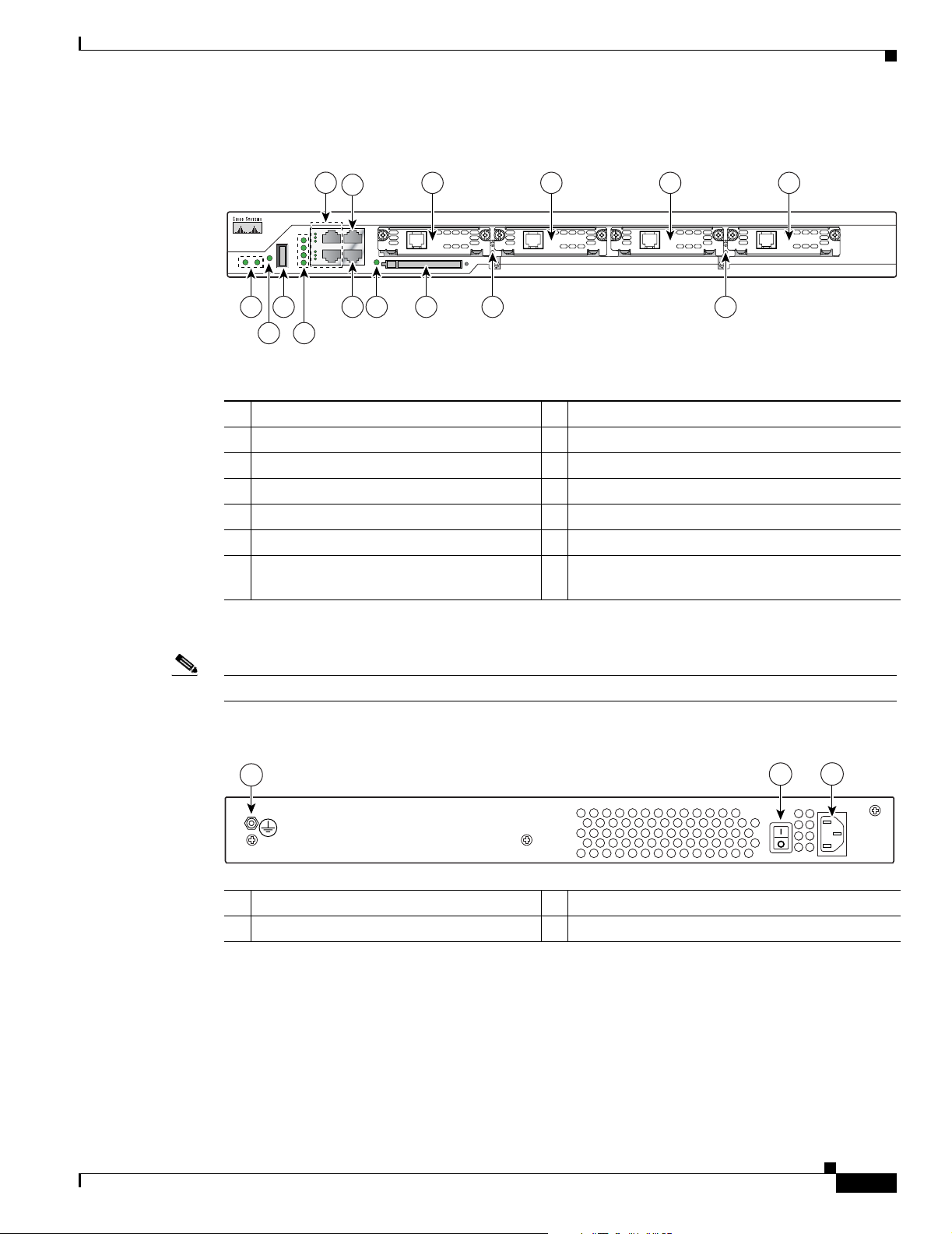
Chassis Views
Figure 7 Front Panel of the Cisco 2801 Router
Double-wide HWICs can go into slots 0 and 1, and into slots 2 and 3.
Note Slot 0 does not support PRI on T1/E1 VWICs, only channel-associated signaling (CAS) digital voice.
Figure 8 Back Panel of the Cisco 2801 Router
1 Slot 0 (VIC or VWIC, for voice only) 8 Auxiliary Power (AUX/PWR) LED
2 Slot 1 (WIC, VIC, VWIC, or HWIC) 9 Universal serial bus (USB) port
3 Slot 2 (WIC, VIC, or VWIC) 10 AIM/PVDM LEDs
4 Slot 3 (WIC, VIC, VWIC, or HWIC) 11 Auxiliary port
5 Console port 12 Compact flash (CF) LED
6 Fast Ethernet ports and LEDs 13 External CompactFlash memory card slot
7 System LEDs 14 Removable center card guides to allow
double-wide HWIC-D installation
958
1
6
1234
5
6
7 9 11 12 13 14 14
8 10
1 Input power connector 3 Chassis ground connection
2 On/Off switch
95905
3
1
2
12
Overview of Cisco 2800 Series Routers
OL-5783-01
Chassis Views
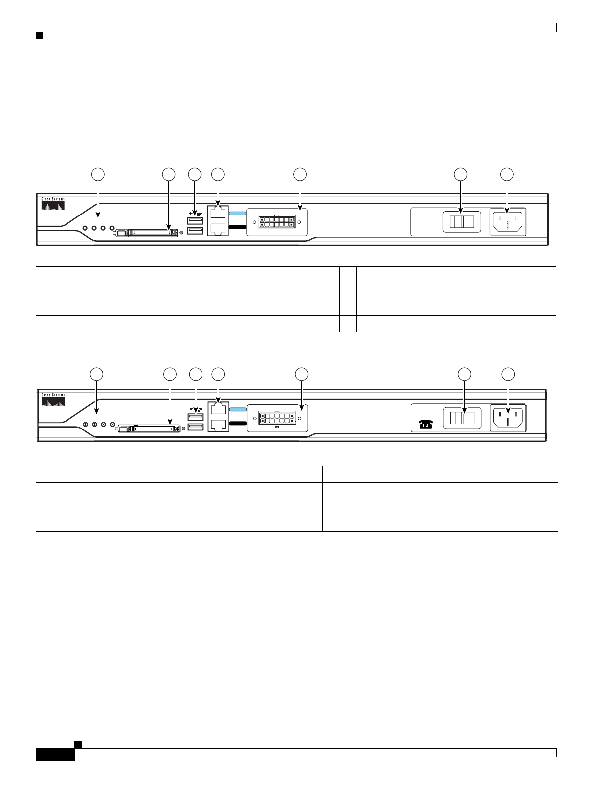
Cisco 2811 Chassis
Figure 9, Figure 10, and Figure 11 show the front panel of a Cisco 2811 router. Figure 12 shows the rear
panel of a Cisco 2811 router.
Figure 9 Front Panel of Cisco 2811 Router with AC Input Power and Without IP Phone Power Output
Figure 10 Front Panel of Cisco 2811 Router with AC Input Power and with IP Phone Power Output
1 Input power connection 5 Universal serial bus (USB) ports
2 On/Off switch 6 External CompactFlash memory card slot
3 Cisco redundant power supply connector (covered if not used) 7 LED indicators
4 Console and auxiliary ports
1 Input power connection 5 Universal serial bus (USB) ports
2 On/Off switch 6 External CompactFlash memory card slot
3 Cisco redundant power supply connector (covered if not used) 7 LED indicators
4 Console and auxiliary ports
95551
Do Not Remove During Network Operation
COMPACT FLASH
CONSOLE
0
1
OPTIONAL RPS INPUT
12V 11A
AUX
SYS
PWR
AUX/
PWR
SYS
ACT CF
100-240 V~ 2A
50/60 Hz
124567 3
95550
CONSOLE
OPTIONAL RPS INPUT
12V 11A
AUX
SYS
PWR
AUX/
PWR
SYS
ACT CF
-48V 4A
124567 3
0
1
100-240V~ 8A
50/60 Hz
Do Not Remove During Network Operation
COMPACT FLASH

13
Overview of Cisco 2800 Series Routers
OL-5783-01
Chassis Views
Figure 11 Front Panel of Cisco 2811 Router with DC Input Power
Figure 12 Rear Panel of Cisco 2811 Router
1 Input power connection 5 Universal serial bus (USB) ports
2 On/Stand-by switch
1
1. This switch does not turn off the power supply completely, but rather puts it in stand-by mode.
6 External CompactFlash memory card slot
3 Cisco redundant power supply connector (covered if not used) 7 LED indicators
4 Console and auxiliary ports
1 Screw holes for ground lug 5 High-speed WAN interface card slot 1
2 Fast Ethernet port 0/0 6 High-speed WAN interface card slot 2
3 Fast Ethernet port 0/1 7 High-speed WAN interface card slot 3
4 High-speed WAN interface card slot 0 8 Network module enhanced (NME) slot
1
1. The network module slot is compatible with Cisco network modules of type NM (network module) and NME (network module enhanced).
95552
Do Not Remove During Network Operation
COMPACT FLASH
CONSOLE
0
1
OPTIONAL RPS INPUT
12V 11A
AUX
SYS
PWR
AUX/
PWR
SYS
ACT CF
4567 3
24-60 V 8A
12
A= ACT
FE 0/1
PVDM1 PVDM0 AIM1 AIM0
FE 0/0
S= SPEED
A= FDX
A= LINK
A
F
S
L
A
F
S
L
H
W
I
C
2
H
W
I
C
0
H
W
I
C
3
H
W
I
C
1
1
23
95556
45
67
1
8
14
Overview of Cisco 2800 Series Routers
OL-5783-01
Chassis Views
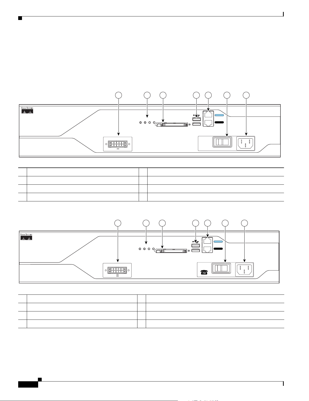
Cisco 2821 and Cisco 2851 Chassis
Figure 13, Figure 14, and Figure 15 show the front panel of Cisco 2821 and Cisco 2851 routers.
Figure 16 shows the rear panel of a Cisco 2821 router. Figure 17 shows the rear panel of a Cisco 2851
router.
Figure 13 Front Panel of Cisco 2821 and Cisco 2851 Routers with AC Input Power and Without IP Phone Power Output
Figure 14 Front Panel of Cisco 2821 and Cisco 2851 Routers with AC Input Power and IP Phone Power Output
1 Input power connection 5 External CompactFlash memory card slot
2 On/Off switch 6 LED indicators
3 Console and auxiliary ports 7 Cisco redundant power supply connector (covered if not used)
4 Universal serial bus (USB) ports
1 Input power connection 5 External CompactFlash memory card slot
2 On/Off switch 6 LED indicators
3 Console and auxiliary ports 7 Cisco redundant power supply connector (covered if not used)
4 Universal serial bus (USB) ports
95553
Do Not Remove During Network Operation
COMPACT FLASH
0
1
OPTIONAL RPS INPUT
SYS
PWR
AUX/
PWR
SYS
ACT CF
12V 18A
100-240 V~ 3A
50/60 Hz
1457 6 3
CONSOLE
AUX
2
95554
Do Not Remove During Network Operation
COMPACT FLASH
0
1
OPTIONAL RPS INPUT
SYS
PWR
AUX/
PWR
SYS
ACT CF
12V 18A
-48V 8A
1457 6 3
CONSOLE
AUX
2
100-240V~ 8A
50/60 Hz
Loading...