


Cisco Catalyst 2960-L Series
Easy Setup Guide
You can easily set up your switch in this step-by-step guide.
1 Connecting PC to Switch
2 Configuring Switch

1 ConnectingPCtoSwitch
1-1 Before You Begin
Before you begin the installation, make sure that you have the following equipment:
● Catalyst 2960-L (the switch) |
● AC Power Cord |
● Ethernet Cable |
● PC |
Make sure that nothing is connected to the switch and your PC settings are configured to use DHCP.
1-2 Connecting PC to Switch
1Connect the AC power cord to the AC power connector of the switch and a grounded AC outlet.
Power the switch.
2
2Confirm that the SYST LED and STAT LED are solid green.
After the switch powers on, it begins the power-on self-test (POST). During POST, the each LED blinks. When POST is completed, the SYST LED and STAT LED turn solid green.
3 4
 MEMO
MEMO
You can confirm the connection by the "ping 10.0.0.1" command from your PC to the switch.
 Caution
1 Connecting PC to Switch
3Press and hold the Mode button.
4Confirm that all the LEDs turn green.
Press the Mode button when the SYST and STAT LED turn green, hold the Mode button until all the LEDs next to the Mode button turn green.
5Connect the Ethernet cable to the Ethernet port of the switch, and the other end of the cable to the Ethernet port on your PC.
Wait until the port LEDs on the switch and your PC are green or blinking green. Green LEDs indicate a successful connection.
At step , if the SYST LED does not turn solid green, or turns amber, the switch failed the POST, reconnect the AC power cord to the switch AC power connector and a grounded AC outlet. Nevertheless the SYST LED does not turn solid green, or turns amber, contact your Cisco representative or reseller.
At step , if the LEDs next to the Mode button blink when you press the button, release it. Blinking LEDs indicate that the switch is already configured and cannot go into Express Setup mode.
At step , the switch port to connect an Ethernet cable is the RJ-45 Ethernet port, not the RJ-45 console port. The RJ-45 Ethernet ports are numbered 1 to 8 on the 8-port model, 1 to 16 on the 16-port model, 1 to 24 on the 24-port model, 1 to 48 on the 48-port model.
Cisco Catalyst 2960-L Series Easy Setup Guide
2 Configuring Switch
2-1 Before You Begin
Before you begin the configuration, make sure that you have the following information.
●IP Address of the Default Gateway (Router)
●IP Address and Subnet Mask for the Switch
2-2 Logging in to Configuration Setup Wizard
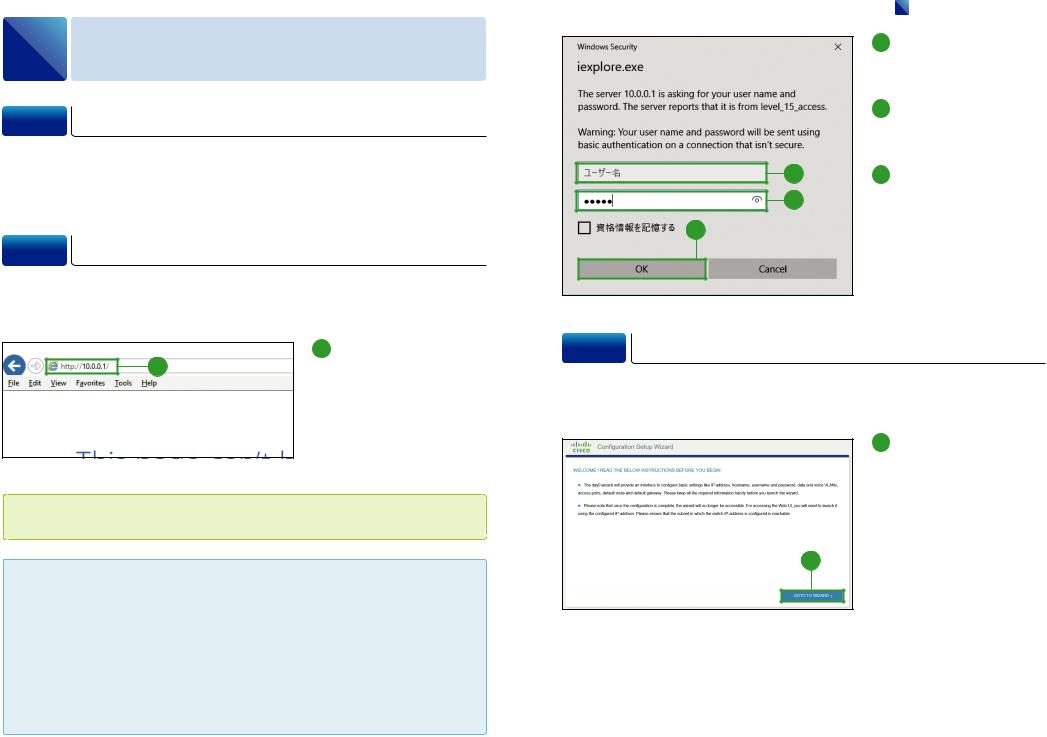
When you first set up the switch, use the Configuration Setup Wizard to enter the initial IP information. Launch a Web browser on your PC, and log in to the Web UI.
1 Enter the IP address
1 "10.0.0.1" into a web browser address bar, and press Enter key.
The authentication dialog box appears.
 MEMO
MEMO
The switch has a default IP address "10.0.0.1" and a secondary IP address "10.0.0.3".
 Caution
If the authentication dialog box does not appear, make sure that:
All the LEDs next to the Mode button turn green.
You connect a straight-through cable to an Ethernet port on the switch and the PC.Any pop-up blockers or proxy settings on your browser are disabled and that any wireless client is disabled on your PC or laptop.
Your PC settings use DHCP. During the Express Setup mode, the switch acts as a DHCP server. If your PC has a static IP address, temporarily configure your PC settings to use DHCP.
2
3
4
|
2 Configuring Switch |
2 |
E n t e r t h e d e f a u l t |
|
username "cisco" in the |
|
[Username]. |
3 |
E n t e r t h e d e f a u l t |
|
password "cisco" in the |
|
[Password]. |
4 |
Click [OK]. |
The Configuration Setup Wizard window appears.
2-3 Basic Configuration
After logging in to the Web UI, the Configuration Setup Wizard automatically appears to help you perform initial configuration.
1 Click [GO TO WIZARD].
The BASIC CONFIGURATION window appears.
1
Cisco Catalyst 2960-L Series Easy Setup Guide
 Loading...