


2305-BTS2-R1
Table of contents
 Loading...
Navini Networks, Inc. Ripwave Base Station I&C Guide
98
Export BTS Data
After successfully calibrating a BTS and before performing the calibration verification
procedure, export the BTS configuration data to a text file. This is done by highlighting the
specific BTS in the Configuration and Alarms Manager (CAM) window, and on the Main Menu
select File > Export BTS Data. This text file will be used as input by the “IC Closeout Tool”
(Part Number 40-00217-00), shown in Appendix V.
Perform the Calibration Verification Procedure
Base Station Calibration Verification is a set of procedures to verify that the equipment has
passed calibration and that the RF portion of the equipment is operating within acceptable
parameters. The results of the tests should be documented in the Base Station Calibration
Verification Form, which is part of the “IC Closeout Tool” (Part Number 40-00217-00).
This procedure is described in Appendix Q.
Single Antenna Element Test
The object of the RFS Single Antenna Element Test Procedure is to verify the functionality of
each antenna element in the Ripwave Radio Frequency Subsystem (RFS). The 8 antenna
elements work together to create the beam forming effect that results from using a Smart
Antenna - Phased Array technology. Using 8 combined antenna elements concentrates the beam
of radiation, adding up to 9 dB of gain, both in the downlink and in the uplink
In the downlink there is an additional 9 dB of gain because there are 8 antenna elements
transmitting simultaneously in the RFS. This gain is not available in the uplink because there is
only one antenna element transmitting at any time in the Modem.
In a Non-TTA BTS, each antenna element has an associated Low Noise Amplifier (LNA) in the
RFS and a Power Amplifier (PA) in the RF Shelf of the BTS. In a TTA BTS, each antenna
element has an associated PA in the RFS and an RF Converter (RFC) in the BTS shelf. In order
to verify that each individual antenna element is working properly, we have to power off the
LNA/PA/RFCs for all the antenna elements, then turn them on individually one at a time and
verify that a test Modem can communicate with the base station through that single antenna
element (Appendix R
).
Install & Test Customer EMS Operations
If you have been using a Test EMS up to this point, you will now need to install and test the
customer’s EMS server. This involves installing the EMS Server and Client on a computer that is
connected through the system backhaul. When connecting the Ripwave equipment to the

Navini Networks, Inc. Ripwave Base Station I&C Guide
99
backhaul, refer to the Regulatory Information in Chapter 1, Page 8 – specifically regarding
cabling to Ethernet or T1/E1 backhauls. Ethernet connections require a UL497B listed protection
device to be installed between the BTS and the first network device. T1/E1 connections must be
routed from the BTS through a UL497 listed protection device at the demarcation point. The
interconnect cables for T1/E1 backhauls must be a minimum #26 AWG wire, in accordance with
NEC/CEC standards. If the customer’s EMS is already installed and has been used for testing
purposes, skip to the “Verify System Performance” section of this chapter.
Install EMS Software
The EMS software installation procedures can be found in the EMS Software Installation Guide,
P/N 40-00017-00. After installing the EMS Server and Client applications, the EMS needs to be
configured with the settings that are designated for the Base Station. The settings are found in the
Network Architecture Plan provided by the customer.
Ensure connection between the Base Station and the backhaul. The connection to the Base
Station will be either an Ethernet connection or T1 connections.
Verify EMS to Base Station Connectivity
Follow the steps below to ensure the EMS and Base Station can communicate.
Step 1. Open a Command Prompt window on the computer where the EMS is installed.
Step 2. Ping the Base Station using the CLI command ping <base station ip address>. Verify
that a reply from the Base Station is received.
Perform Calibration Using Customer’s EMS
This step is necessary only if you have been using a Test EMS up to this point. You will need to
install the customer’s EMS server and software. Calibrate the Base Station using the customer’s
EMS. Follow the same calibration procedures described earlier in this chapter, Calibrate the Base
Station. Perform the procedure three times and make sure that the results are stable (±3).

Navini Networks, Inc. Ripwave Base Station I&C Guide
100
Verify System Performance
Location (FTP) Test
Location Tests are performed to see if the system file transfer functions are working as predicted
between Modem and Base Station. First you perform three uploads and three downloads from
one locations in line-of-sight (LOS) with the Base Station at a distance of about 2 km. Then you
perform three uploads and three downloads at several additiona locations in either line-of-sight
or non-line-of-sight (NLOS) with the Base Station. The number recommended number of
additional locations is 4 for panel antennas and 7 for Omni antennas.
The Location (FTP) Test procedure is described in Appendix S
. The form used to collect the
data is contained in the “IC Closeout Tool” (Part Number 40-00217-00).
The results are sent to Navini Networks Technical Support for evaluation
Drive Study
The Drive Study is performed to verify if the system’s coverage area is as predicted and, if
necessary, to fine-tune the RF model.
The procedure is described in Appendix T. The form used to collect the data is contained in the
“IC Closeout Tool” (Part Number 40-00217-00).
You will perform the Drive Study by driving back and forth through a sector, staying on major
roads about a kilometer apart. Special attention has to be paid to the null and fringe areas. You
will follow this scheme for each sector in the site, recording the results of all tests. The test
results will be sent for evaluation, along with the Location (FTP) test results, to Navini Networks
Technical Support. If the results are not adequate, Technical Support will have you adjust some
of the RF parameters and perform the Drive Study again.
Verify System Operation With Multiple Modems
Set up three computers with Modems connected to them. Perform file transfers from all three
computers to verify Base Station operation.

Navini Networks, Inc. Ripwave Base Station I&C Guide
101
Back Up EMS Database
After all system installation and commissioning activities are complete, perform a backup of the
EMS database. The procedure can be found in the EMS Administration Guide. Place the backup
files on a different system server where they will be periodically backed up on a tape drive.
Customer Acceptance
To conclude the installation and commissioning activities, gather all of the required documents
and forms from the installation and commissioning procedures to create a comprehensive system
I&C package. Refer to Appendix U for a summary of the documentation package. The customer
and Navini Networks will sign the Customer Acceptance Form. A copy of this form is provided
in Appendix W. The signed form and the system I &C package are provided to the customer.
The original, signed Customer Acceptance Form and system I &C package are stored in the
Navini Networks Technical Support database.
Navini Networks, Inc. Ripwave Base Station I&C Guide
102
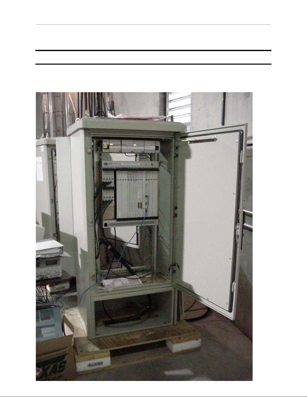
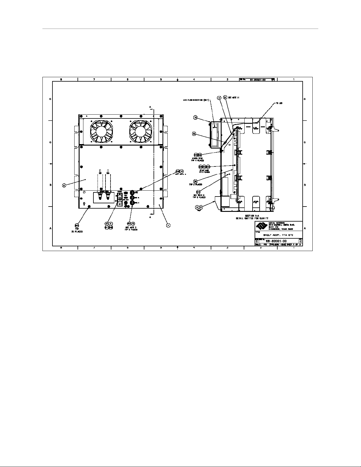
Appendix C: BTS Specifications
Figure C7: TTA Digital Chassis (Front)
Navini Networks, Inc. Ripwave Base Station I&C Guide
103
Figure C8: TTA Digital Chassis (Back)
Navini Networks, Inc. Ripwave Base Station I&C Guide
104
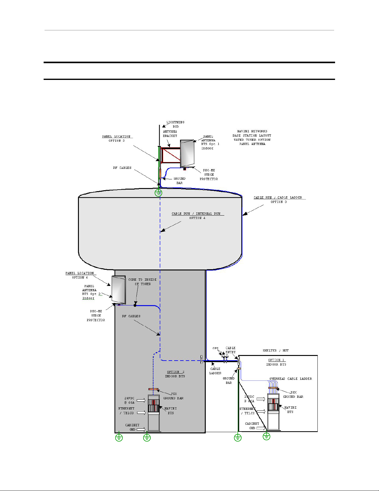
Appendix G: Sample Base Station Drawing
Figure G1: Sample Base Station Drawing
Loading...