


Text Part Number: 78-3158-04
PA-5EFL Ethernet 10BASE-FL
Port Adapter Installation and
Configuration
Product Numbers: PA-5EFL and PA-5EFL=
Introduction
This configuration note describes the installation and configuration of the Ethernet 10BASE-FL port adapter (PA-5EFL[=]), which can be used in the following platforms:
•Cisco 7200 series routers—which consist of the 2-slot Cisco 7202, 4-slot Cisco 7204 and Cisco 7204VXR, and the 6-slot Cisco 7206 and Cisco 7206VXR
•Cisco uBR7246 universal broadband router
•Second-generation Versatile Interface Processor (VIP2) in all Cisco 7500 series routers and in Cisco 7000 series routers using the 7000 Series Route Switch Processor (RSP7000) and 7000 Series Chassis Interface (RSP7000CI) installed.
Contents
The following sections are included in this document:
•
•
•
•
•
If You Need More Information, page 2
Port Adapter Installation Prerequisites, page 2
What Is the 5EFL Port Adapter?, page 8
VIP2 and the 5EFL Port Adapter, page 11
Cisco 7200 Series and the 5EFL Port Adapter, page 25
The section “Cisco Connection Online,” on page 38, includes general reference information.
Corporate Headquarters
Cisco Systems, Inc.
170 West Tasman Drive
San Jose, CA 95134-1706
USA
Copyright © 1998 |
|
Cisco Systems, Inc. |
1 |
All rights reserved. |

If You Need More Information
If You Need More Information
The Cisco IOS software running your router contains extensive features and functionality. The effective use of many of many of these features is easier if you have more information at hand. For additional information on configuring and maintaining the Cisco 7000 series, Cisco 7200 series, and Cisco 7500 series routers, and PA-5EFL, the following documentation resources are available:
•For hardware installation and maintenance information on the Cisco 7000 series and Cisco 7500 series routers, and the VIP2, refer to the following publications:
—The installation and configuration guide that shipped with your Cisco 7000 series or Cisco 7500 series router
—Second-Generation Versatile Interface Processor (VIP2) Installation and Configuration (for VIP2 users only)
•For hardware installation and maintenance information on the Cisco 7200 routers, refer to the following publications that shipped with your router:
—Cisco 7202 Installation and Configuration Guide
—Cisco 7204 Installation and Configuration Guide
—Cisco 7206 Installation and Configuration Guide
•For hardware installation and maintenance information on the Cisco 7200VXR routers, refer to the Cisco 7200 VXR Installation and Configuration Guide publication that shipped with your Cisco 7200VXR router.
•To view Cisco documentation or obtain general information about the documentation, refer to the “Cisco Connection Online” section on page Reference, the “Cisco Connection Online” section on page 38, or call Customer Service at 800 553-6387 or 408 526-7208. Customer Service hours are 5:00 a.m. to 6:00 p.m. Pacific time, Monday through Friday (excluding company holidays). You can also send e-mail to cs-rep@cisco.com, refer to the Cisco Information Packet that shipped with your router, or access Cisco documentation on the World Wide Web at http://www.cisco.com, http://www-china.cisco.com, or http://www-europe.cisco.com.
Port Adapter Installation Prerequisites
This section provides software requirements, a list of parts and tools you will need to perform the port adapter installation, and safety and ESD-prevention guidelines to help you avoid injury and damage to the equipment during installation. Also included is information on the systems in which port adapters can be installed and overview information on interface specifications.
The following sections discuss general information and information about port adapter installation requirements:
•
•
•
•
•
Software and Hardware Requirements
Tools and Parts Required, page 3
Safety Guidelines, page 4
Ethernet and Ethernet 10BASE-FL Overview, page 6
IEEE 802.3 10BASE-FL Specifications, page 7
2 PA-5EFL Ethernet 10BASE-FL Port Adapter Installation and Configuration

Tools and Parts Required
Tools and Parts Required
You need the following tools and parts to install a port adapter. If you need additional equipment, contact a service representative for ordering information.
•PA-5EFL(=) port adapter and one of the following:
—VIP2-15(=), VIP2-20=, VIP2-40(=) or VIP2-50(=)
—Cisco 7200 series router with at least one available port adapter slot
•Cables appropriate for the port adapter interfaces (ST-type optical-fiber cables are not available from Cisco Systems; they are available from outside commercial cable vendors.)
•Number 1 Phillips and a 3/16-inch, flat-blade screwdriver.
•Your own ESD-prevention equipment or the disposable grounding wrist strap included with all upgrade kits, FRUs, and spares.
Software and Hardware Requirements
Table 1 |
PA-5EFL Port Adapter Software Requirements |
|
|
Router Platform |
Minimum Cisco IOS Release |
|
|
Cisco 7000 series and Cisco 7500 series |
|
• With VIP2-15 or VIP2-40 |
Cisco IOS Release 11.1(472) or a later release of Cisco IOS Release 11.1 |
|
Cisco IOS Release 11.1(6)CA or a later release of Cisco IOS Release 11.1 CA |
|
Cisco IOS Release 11.2(1) or a later release of Cisco IOS Release 11.2 |
|
Cisco IOS Release 11.2(6)P or a later release of Cisco IOS Release 11.1 P |
|
Cisco IOS Release 11.1(14)CA or a later release of Cisco IOS Release 11.1 CA |
• With VIP2-50 |
Cisco IOS Release 11.1(14)CA or a later release of Cisco IOS Release 11.1 CA |
|
|
Cisco 7200 series |
|
• Cisco 7204VXR and Cisco 7206VXR |
Cisco IOS Release 12.0(3)T or a later release of Cisco IOS Release 12.0 T |
|
Cisco IOS Release 12.0(2)XE2 or a later release of Cisco IOS Release 12.0 XE |
• Cisco 7204 and Cisco 7206 |
Cisco IOS Release 11.1(9)CA1 or a later release of Cisco IOS Release 11.1 CA |
• Cisco 7202 |
Cisco IOS Release 11.1(19)CC1 or a later release of Cisco IOS Release 11.1 C |
|
Cisco IOS Release 11.3(4)AA or a later release of Cisco IOS Release 11.3 AA |
|
|
In the Cisco 7000 series or Cisco 7500 series routers, the 5EFL port adapter requires the following VIP2 models:
•
•
•
•
VIP2-15 (1 MB of SRAM, 8 MB of DRAM)
VIP2-20 (1 MB of DRAM, 16 MB of SRAM)
VIP2-40 (2 MB of SRAM, 32 MB of DRAM)
VIP2-50 (4 to 8 MB of SRAM, 32 to 128 MB of DRAM)
Caution To prevent system problems, the VIP2 requires that the Cisco 7000 series router has the RSP7000 and RSP7000CI installed. The VIP2 will not operate properly with the Route Processor (RP), Switch Processor (SP), or Silicon Switch Processor (SSP) installed in the Cisco 7000 series router.
PA-5EFL Ethernet 10BASE-FL Port Adapter Installation and Configuration 3

Safety Guidelines
Note Port adapters used with the 7200 VXR routers require the correct base hardware revision in order to function. The following error message will occur on bootup if the incorrect hardware revision is used:
> PA-3-REVNOTSUPPORTED:PA in slot 1 (Ethernet) requires base h/w revision of (1.5)
for this chassis
Use the sh diag command to display the hardware revision. (See the “Using show Commands to
Display Interface Information” section on page 34).
Note The minimum recommended VIP2 model is a VIP2-15.
Safety Guidelines
Following are safety guidelines that you should follow when working with any equipment that connects to electrical power or telephone wiring.
Safety Warnings
Safety warnings appear throughout this publication in procedures that, if performed incorrectly, may harm you. A warning symbol precedes each warning statement.
Warning Means danger. You are in a situation that could cause bodily injury. Before you work on any equipment, be aware of the hazards involved with electrical circuitry and be familiar with standard practices for preventing accidents. To see translations of the warnings that appear in this publication, refer to the
Regulatory Compliance and Safety Information document that accompanied this device.
Waarschuwing Dit waarschuwingssymbool betekent gevaar. U verkeert in een situatie die lichamelijk letsel kan veroorzaken. Voordat u aan enige apparatuur gaat werken, dient u zich bewust te zijn van de bij elektrische schakelingen betrokken risico's en dient u op de hoogte te zijn van standaard maatregelen om ongelukken te voorkomen. Voor vertalingen van de waarschuwingen die in deze publicatie verschijnen, kunt u het document Regulatory Compliance and Safety Information (Informatie over naleving van veiligheidsen andere voorschriften) raadplegen dat bij dit toestel is ingesloten.
Varoitus Tämä varoitusmerkki merkitsee vaaraa. Olet tilanteessa, joka voi johtaa ruumiinvammaan. Ennen kuin työskentelet minkään laitteiston parissa, ota selvää sähkökytkentöihin liittyvistä
vaaroista ja tavanomaisista onnettomuuksien ehkäisykeinoista. Tässä julkaisussa esiintyvien varoitusten käännökset löydät laitteen mukana olevasta Regulatory Compliance and Safety Information -kirjasesta (määräysten noudattaminen ja tietoa turvallisuudesta).
Attention Ce symbole d'avertissement indique un danger. Vous vous trouvez dans une situation pouvant causer des blessures ou des dommages corporels. Avant de travailler sur un équipement, soyez conscient des dangers posés par les circuits électriques et familiarisez-vous avec les procédures couramment utilisées pour éviter les accidents. Pour prendre connaissance des traductions d’avertissements figurant dans cette publication, consultez le document Regulatory Compliance and Safety Information (Conformité aux règlements et consignes de sécurité) qui accompagne cet appareil.
4 PA-5EFL Ethernet 10BASE-FL Port Adapter Installation and Configuration

Safety Warnings
Warnung Dieses Warnsymbol bedeutet Gefahr. Sie befinden sich in einer Situation, die zu einer Körperverletzung führen könnte. Bevor Sie mit der Arbeit an irgendeinem Gerät beginnen, seien Sie sich der mit elektrischen Stromkreisen verbundenen Gefahren und der Standardpraktiken zur Vermeidung von Unfällen bewußt. Übersetzungen der in dieser Veröffentlichung enthaltenen Warnhinweise finden Sie im Dokument Regulatory Compliance and Safety Information
(Informationen zu behördlichen Vorschriften und Sicherheit), das zusammen mit diesem Gerät geliefert wurde.
Avvertenza Questo simbolo di avvertenza indica un pericolo. La situazione potrebbe causare infortuni alle persone. Prima di lavorare su qualsiasi apparecchiatura, occorre conoscere i pericoli relativi ai circuiti elettrici ed essere al corrente delle pratiche standard per la prevenzione di incidenti. La traduzione delle avvertenze riportate in questa pubblicazione si trova nel documento Regulatory Compliance and Safety Information (Conformità alle norme e informazioni sulla sicurezza) che accompagna questo dispositivo.
Advarsel Dette varselsymbolet betyr fare. Du befinner deg i en situasjon som kan føre til personskade. Før du utfører arbeid på utstyr, må du vare oppmerksom på de faremomentene som elektriske kretser innebærer, samt gjøre deg kjent med vanlig praksis når det gjelder å unngå ulykker. Hvis du vil se oversettelser av de advarslene som finnes i denne publikasjonen, kan du se i dokumentet Regulatory Compliance and Safety Information (Overholdelse av forskrifter og sikkerhetsinformasjon) som ble levert med denne enheten.
Aviso Este símbolo de aviso indica perigo. Encontra-se numa situação que lhe poderá causar danos físicos. Antes de começar a trabalhar com qualquer equipamento, familiarize-se com os perigos relacionados com circuitos eléctricos, e com quaisquer práticas comuns que possam prevenir possíveis acidentes. Para ver as traduções dos avisos que constam desta publicação, consulte o documento Regulatory Compliance and Safety Information (Informação de Segurança e Disposições Reguladoras) que acompanha este dispositivo.
¡Advertencia! Este símbolo de aviso significa peligro. Existe riesgo para su integridad física. Antes de manipular cualquier equipo, considerar los riesgos que entraña la corriente eléctrica y familiarizarse con los procedimientos estándar de prevención de accidentes. Para ver una traducción de las advertencias que aparecen en esta publicación, consultar el documento titulado Regulatory Compliance and Safety Information (Información sobre seguridad y conformidad con las disposiciones reglamentarias) que se acompaña con este dispositivo.
Varning! Denna varningssymbol signalerar fara. Du befinner dig i en situation som kan leda till personskada. Innan du utför arbete på någon utrustning måste du vara medveten om farorna med elkretsar och känna till vanligt förfarande för att förebygga skador. Se förklaringar av de varningar som förkommer i denna publikation i dokumentet Regulatory Compliance and Safety Information (Efterrättelse av föreskrifter och säkerhetsinformation), vilket medföljer denna anordning.
Electrical Equipment Guidelines
Follow these basic guidelines when working with any electrical equipment:
•Before beginning any procedures requiring access to the chassis interior, locate the emergency power-off switch for the room in which you are working.
•Disconnect all power and external cables before moving a chassis.
•Do not work alone when potentially hazardous conditions exist and never assume that power has been disconnected from a circuit; always check.
•Do not perform any action that creates a potential hazard to people or makes the equipment unsafe. Carefully examine your work area for possible hazards such as moist floors, ungrounded power extension cables, and missing safety grounds.
PA-5EFL Ethernet 10BASE-FL Port Adapter Installation and Configuration 5

Safety Guidelines
Telephone Wiring Guidelines
Use the following guidelines when working with any equipment that is connected to telephone wiring or to other network cabling:
•
•
Never install telephone wiring during a lightning storm.
Never install telephone jacks in wet locations unless the jack is specifically designed for wet locations.
•Never touch uninsulated telephone wires or terminals unless the telephone line has been disconnected at the network interface.
•Use caution when installing or modifying telephone lines.
Preventing Electrostatic Discharge Damage
Electrostatic discharge (ESD) damage, which can occur when electronic cards or components are improperly handled, results in complete or intermittent failures. Port adapters and processor modules consist of printed circuit boards that are fixed in metal carriers. Electromagnetic interference (EMI) shielding and connectors are integral components of the carrier. Although the metal carrier helps to protect the board from ESD, use a preventive antistatic strap during handling.
Following are guidelines for preventing ESD damage:
•Always use an ESD wrist or ankle strap and ensure that it makes good skin contact.
•Connect the equipment end of the strap to an unfinished chassis surface.
•When installing a component, use any available ejector levers or captive installation screws to properly seat the bus connectors in the backplane or midplane. These devices prevent accidental removal, provide proper grounding for the system, and help to ensure that bus connectors are properly seated.
•When removing a component, use any available ejector levers or captive installation screws to release the bus connectors from the backplane or midplane.
•Handle carriers by available handles or edges only; avoid touching the printed circuit boards or connectors.
•Place a removed component board-side-up on an antistatic surface or in a static shielding container. If you plan to return the component to the factory, immediately place it in a static shielding container.
•Avoid contact between the printed circuit boards and clothing. The wrist strap only protects components from ESD voltages on the body; ESD voltages on clothing can still cause damage.
•Never attempt to remove the printed circuit board from the metal carrier.
Caution For safety, periodically check the resistance value of the antistatic strap. The measurement should be between 1 and 10 megohms.
Ethernet and Ethernet 10BASE-FL Overview
The term Ethernet is commonly used for all carrier sense multiple access/collision detection (CSMA/CD) local-area networks (LANs) that generally conform to Ethernet specifications, including IEEE 802.3. Ethernet Version 2 and IEEE 802.3 were based on, and developed shortly after, Ethernet Version 1. The slight differences between Ethernet and IEEE 802.3 are implemented in hardware, and both are supported automatically by the 5EFL without any hardware configuration
6 PA-5EFL Ethernet 10BASE-FL Port Adapter Installation and Configuration

IEEE 802.3 10BASE-FL Specifications
changes. Together, Ethernet and IEEE 802.3 are the most widely used LAN protocols. They are well suited to applications where a local communication medium must carry sporadic, occasionally heavy traffic at high peak data rates.
The term 10BASE-FL is an abbreviation for 10 Mbps transmission, Baseband medium, F for fiber, and L for link, as defined in the 10BASE-FL specification. The Ethernet specifications call the 5EFL device a transceiver, and it is connected to the station with a transceiver cable. The 5EFL port adapter is not an end station. The IEEE 802.3 specifications refer to the same type of device as a media attachment unit (MAU). Stations on a CSMA/CD LAN can access the network at any time. Before sending data, the station listens to the network to see of it is already in use. If it is, the station waits until the network is not in use, then transmits. A collision occurs when two stations listen for network traffic, hear none, and transmit simultaneously. When this happens, both transmissions are damaged, and the stations must retransmit. The stations detect the collision and use backoff algorithms to determine when they should retransmit.
Both Ethernet and IEEE 802.3 are broadcast networks, which means that all stations see all transmissions. Each station must examine received frames to determine whether it is the intended destination and, if it is, pass the frame to a higher protocol layer for processing. IEEE 802.3 specifies several different physical layers, and Ethernet defines only one. Each IEEE 802.3 physical layer protocol has a name that summarizes its characteristics in the format speed/signaling method/segment length where speed is the LAN speed in Mbps, signaling method is the signaling method used (either Baseband or Broadband), and segment length is the maximum length between stations in hundreds of meters. The maximum distances for Ethernet network segments and connections depend on the type of transmission cable used; for example, fiber-optic cable (10BASE-FL).
IEEE 802.3 10BASE-FL Specifications
Table 2 summarizes the characteristics of IEEE 802.3 Ethernet and Ethernet 10BASE-FL.
Table 2 |
IEEE 802.3 Ethernet and Ethernet 10BASE-FL Physical Characteristics |
||
|
|
|
|
|
IEEE 802.3 |
10BASE-FL |
|
Parameter |
Ethernet |
Ethernet |
|
|
|
|
|
Data Rate (Mbps) |
10 |
10 |
|
|
|
|
|
Signaling method |
Baseband |
Baseband |
|
|
|
|
|
Media |
50-ohm coax (thick) |
Multimode optical fiber |
|
|
|
|
|
Topology |
Bus |
Star |
|
|
|
|
|
Table 3 lists the distance limitations for 10-Mbps transmission over multimode optical-fiber cables.
Table 3 |
Cable Distance Limitations for 10-Mbps 10BASE-FL Transmission |
||
|
|
|
|
Parameter |
|
ST Connections |
|
|
|
|
|
Cable specification |
|
Multimode fiber-optic cable 1 |
|
Maximum segment lengths |
400 m (1,312 ft) for any repeater-to-DTE fiber segment |
||
|
|
500 m (1,640 ft) with four repeaters and five segments |
|
|
|
1000 m (3,280 ft) for any inter-repeater fiber segment |
|
|
|
2km (6,561 ft) without a repeater |
|
|
|
|
|
1 Cisco Systems does not supply fiber-optic cables; these cables are available commercially.
PA-5EFL Ethernet 10BASE-FL Port Adapter Installation and Configuration 7
What Is the 5EFL Port Adapter?
Table 4 lists multimode optical-fiber parameters.
Table 4 |
Multimode Optical-Fiber Parameters |
|
|
Parameter |
Multimode |
|
|
Size |
62.5/125 micrometer (nominal diameter) optical fiber 1 |
Attenuation |
3.75 dB/km, at 850 nanometers (nm) |
|
|
Insertion loss |
< 12.5 dB, at 850 nm |
|
|
Bandwidth |
> 160MHzkm, at 850 nm |
|
|
Propagation delay |
5 microseconds/km |
|
|
1 Specified in IEC Publication 793-2[14].
What Is the 5EFL Port Adapter?
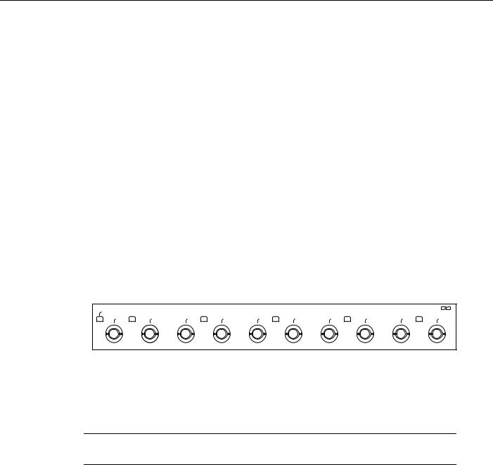
The 5EFL port adapter provides up to five IEEE 802.3 Ethernet 10BASE-FL interfaces. (See Figure 1.) Each Ethernet 10BASE-FL interface allows a maximum bandwidth of 10 Mbps, for a maximum aggregate bandwidth of 50 Mbps, half-duplex. Each 10BASE-FL interface uses two multimode (ST) receptacles for receive (RX) and transmit (TX). All five ports run at wire speed.
Figure 1 5EFL Port Adapter, Faceplate View
EN
ETHERNET-10BFL
RX |
TX |
RX |
TX |
RX |
TX |
RX |
TX |
RX |
TX |
|
0 |
|
1 |
|
2 |
|
3 |
|
4 |
H6471
Port Adapter Locations on the VIP2 and in the Cisco 7200 Series Routers
This section provides information about where you can install the 5EFL port adapter on the VIP2 and in the Cisco 7200 series routers.
Note Port adapters have handles that allow for easy installation and removal; however, they are occasionally not shown in this publication to highlight port adapter faceplate detail.
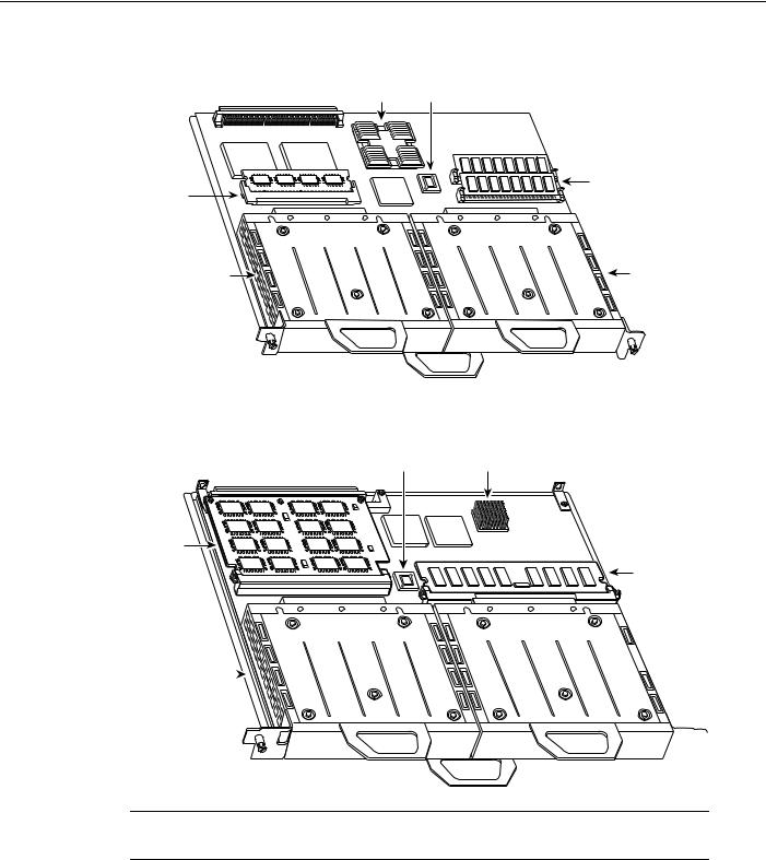
Figure 2 shows a VIP2-15 or VIP2-40 with two installed port adapters. Figure 3 shows a VIP2-50 with two installed port adapters. With the VIP2 oriented as shown, the left port adapter is in port adapter slot 0, and the right port adapter is in port adapter slot 1.
8 PA-5EFL Ethernet 10BASE-FL Port Adapter Installation and Configuration
Port Adapter Locations on the VIP2 and in the Cisco 7200 Series Routers
Figure 2 Two Port Adapters on a VIP2-15 or VIP2-40 (Horizontal Orientation Shown)
Bus connector |
CPU Boot ROM |
|
|
|
U6 |
|
|
|
U2 |
DRAM |
|
SRAM |
SIMMs |
||
U4 |
|||
DIMM U5 |
|
|
|
Port adapter |
|
Port adapter |
|
in slot 0 |
|
in slot 1 |
|
|
|
H6448 |
Figure 3 Two Port Adapters on a VIP2-50 (Horizontal Orientation Shown)
Boot ROM |
CPU |
Bus connector |
|
SRAM |
|
daughter |
DRAM DIMM |
card |
Port adapter  in slot 0

 Port adapter in slot 1
 H10447
Note In the Cisco 7000, Cisco 7507, and Cisco 7513 chassis, the VIP2 is installed vertically. In the Cisco 7010 and Cisco 7505 chassis, the VIP2 is installed horizontally.
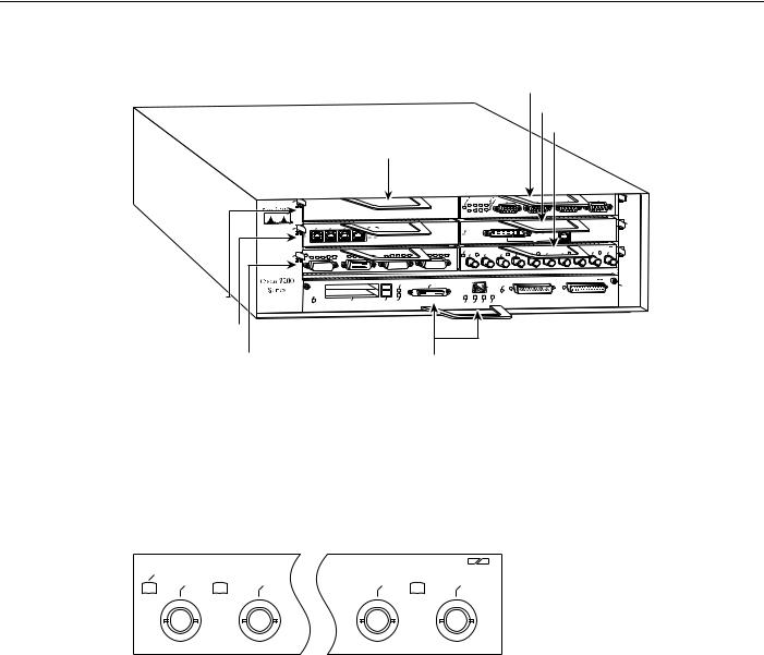
Figure 4 shows a Cisco 7206 with port adapters installed. In the Cisco 7206 and Cisco 7206VXR, port adapter slot 1 is in the lower left position and port adapter slot 6 is in the upper right position. The Cisco 7204 and Cisco 7204VXR are not shown, but have four port adapter slots; PA-5EFL can be installed in any of these four slots.
PA-5EFL Ethernet 10BASE-FL Port Adapter Installation and Configuration 9
What Is the 5EFL Port Adapter?
Figure 4 Port Adapters in the Cisco 7206
5 |
3 |
1 |
Port adapter slot 5 |
Port adapter slot 3 
Port adapter slot 1 
Port adapter slot 6
Port adapter slot 4
Port adapter slot 2
Blank port adapter
|
|
|
|
|
|
|
|
|
|
|
|
|
|
|
TOKEN RING |
|
|
||
|
|
|
|
|
|
|
|
|
|
|
|
|
|
|
|
|
|
|
6 |
|
|
|
|
|
|
ETHERNET 10BT |
|
|
|
|
|
|
|
|
FAST ETHERNET |
|
|
||
|
|
|
|
|
|
ENABLED |
|
|
|
|
LINK |
RJ45 |
|
|
|
|
|
|
|
|
|
|
|
|
|
|
|
|
|
MII |
|
|
|
|
|
4 |
|||
|
|
|
|
|
|
|
|
|
|
|
|
|
|
|
|
||||
|
|
|
|
|
|
|
|
|
|
|
0 |
|
|
|
|
|
|
|
|
|
|
|
|
|
|
FAST SERIAL |
|
|
|
|
|
|
|
|
ETHERNET-10BFL |
|
|
|
|
|
|
|
|
|
|
|
EN |
TX |
RX |
TX |
RX |
TX |
RX |
TX |
RX |
|
TX |
|
2 |
|
|
|
|
|
|
|
RX |
4 |
|
||||||||||
|
|
|
|
|
|
|
|
0 |
|
1 |
2 |
|
|
3 |
|
|
|
|
|
|
|
|
SLOT |
1 |
|
MII |
|
|
|
|
FAST ETHERNET INPUT/OUTPUT CONTROLLER |
|
|
|
|
||||
|
|
|
|
FE |
|
|
|
|
|
|
|
|
|
|
|
|
|
H6422 |
|
ENABLED |
|
|
|
|
|
|
|
|
|
|
|
|
|
|
|
|
|
0 |
|
|
|
|
|
|
|
|
|
|
|
|
|
|
|
|
|
|
|
||
PCMCIA |
EJECT |
SLOT |
0 |
|
|
MII |
RJ45 |
RJ45 |
|
|
|
|
|
|
|
|
|
|
|
|
|
|
|
|
|
|
|
|
|
|
|
|
|||||||
|
|
|
EN |
EN |
LINK |
|
|
|
|
|
|
|
|
|
|
||||
|
|
|
|
|
|
|
|
|
|
|
|
|
|
|
|
|
|
|
|
Port adapter slot 0
5EFL Port Adapter LEDs
The 5EFL port adapter contains the enabled LED, standard on all port adapters, and one status LED for each port, called the link LED. After system initialization, the enabled LED goes on to indicate that the 5EFL port adapter has been enabled for operation. (The LEDs are shown in Figure 5.)
Figure 5 LEDs on the 5EFL Port Adapter, Partial Faceplate View
EN |
|
|
PACKET OVER SONET/SDH |
||
RX |
TX |
RX |
TX |
||
|
|||||
|
|
0 |
|
4 |
|
H6470
The following conditions must be met before the enabled LED goes on:
•The 5EFL interface is correctly connected and receiving power
•The 5EFL-equipped card or chassis contains a valid microcode version that has been downloaded successfully
•The bus recognizes the 5EFL port adapter or 5EFL-equipped VIP2
If any of these conditions is not met, or if the initialization fails for other reasons, the enabled LED does not go on. When a 10BASE-FL port is active, its link LED is on when the 5EFL port adapter is receiving a carrier signal from the network.
10 PA-5EFL Ethernet 10BASE-FL Port Adapter Installation and Configuration
5EFL Port Adapter Multimode Fiber-Optic Cable and Receptacles
5EFL Port Adapter Multimode Fiber-Optic Cable and Receptacles
The interface connectors on the 5EFL port adapter are five pairs of (ST) receptacles, designated as RX and TX. You can use all five connection pairs simultaneously or any combination of each pair individually. Each connection pair supports IEEE 802.3 and Ethernet 10BASE-FL interfaces compliant with appropriate standards. Figure 6 shows the ST fiber-optic cable plug used for RX and TX connections.
Figure 6 Ethernet 10BASE-FL Fiber-Optic Cable Plug (ST Type)


 H1348a
Note The 5EFL interfaces on a VIP2 are configured for 10 Mbps, half duplex, for a maximum aggregate bandwidth of 50 Mbps for half-duplex. Cisco Systems does not supply ST-type optical-fiber cables; these cables are available commercially. For ST-type, multimode optical-fiber cable specifications and transmission distance limitations and requirements, refer to the section “IEEE 802.3 10BASE-FL Specifications” on page 7.
VIP2 and the 5EFL Port Adapter
This section describes the 5EFL port adapter and its use with the VIP2.
The following sections provide additional information specific to the 5EFL port adapter and its use on the VIP2 in Cisco 7000 series and Cisco 7500 series routers:
•
•
•
Installing or Replacing a Port Adapter on a VIP2, page 13
Attaching 5EFL Port Adapter Interface Cables, page 17
Configuring the 5EFL Interfaces, page 17
—Selecting Chassis Slot, Port Adapter, and Ethernet 10BASE-FL Interface Port Numbers, page 18
—Configuring the 5EFL Interfaces, page 17
—Checking the Configuration, page 20
The 5EFL port adapter can be installed on the VIP2 in port adapter slot 0 and port adapter slot 1. Figure 7 shows two 5EFL port adapters installed in port adapter slots 0 and 1 on a VIP2-15 or VIP2-40.
PA-5EFL Ethernet 10BASE-FL Port Adapter Installation and Configuration 11

VIP2 and the 5EFL Port Adapter
Figure 7 |
VIP2-15 or VIP2-40 with Two 5EFL Port Adapter Installed (Horizontal |
||
|
Orientation Shown) |
|
|
|
Bus connector |
CPU Boot ROM |
|
|
|
U6 |
|
SRAM |
|
U2 |
DRAM |
|
SIMMs |
||
DIMM U5 |
|
U4 |
|
Port adapter |
|
|
Port adapter |
|
|
slot 1 |
|
slot 0 |
|
|
|
|
|
|
|
EN |
|
|
|
|
|
|
|
|
ETHERNET-10BFL |
EN |
|
|
|
|
|
|
|
|
ETHERNET-10BFL |
|||
RX |
TX |
RX |
TX |
RX |
TX |
RX |
TX |
RX |
TX |
RX |
TX |
RX |
TX |
RX |
TX |
RX |
TX |
RX |
TX |
|||
|
|
|||||||||||||||||||||
|
|
0 |
|
1 |
|
2 |
|
3 |
|
4 |
|
|
0 |
|
1 |
|
2 |
|
3 |
|
4 |
|
Port adapter handles not shown
H6472
Note Port adapters have a handle attached, but this handle is not shown to allow a full view of detail on each port adapter’s faceplate.
Figure 8 shows two 5EFL port adapters installed in port adapter slots 0 and 1 on a VIP2-50.
Figure 8 |
VIP2-50 with Two 5EFL Port Adapters Installed (Horizontal Orientation Shown) |
|
|
Boot ROM |
CPU |
|
Bus connector |
|
SRAM |
|
daughter |
SDRAM DIMM |
card |
 5EFL in
5EFL in 
port adapter
port adapter
slot 1
slot 0
EN |
|
|
|
|
|
|
|
|
ETHERNET-10BFL |
||
RX |
TX |
RX |
TX |
RX |
TX |
RX |
TX |
RX |
TX |
||
|
|||||||||||
|
|
0 |
|
1 |
|
2 |
|
3 |
|
4 |
|
EN |
|
|
|
|
|
|
|
|
ETHERNET-10BFL |
||
RX |
TX |
RX |
TX |
RX |
TX |
RX |
TX |
RX |
TX |
||
|
|||||||||||
|
|
0 |
|
1 |
|
2 |
|
3 |
|
4 |
|
 H11236
Port adapter handles not shown
12 PA-5EFL Ethernet 10BASE-FL Port Adapter Installation and Configuration
 Loading...