


 Loading...
Preface
Purpose
This guide describes the hardware features of the Catalyst 3650 switches. It describes the physical and performance characteristics of each switch, explains how to install a switch, and provides troubleshooting information.
This guide does not describe system messages that you might receive or how to configure your switch. See the switch software configuration guide, the switch command reference, and the switch system message guide on
http://www.cisco.com/go/cat3650_docs
Document Conventions
This document uses the following conventions.
Note Means reader take note. Notes contain helpful suggestions or references to materials not contained in this manual.
Caution Means reader be careful. In this situation, you might do something that could result in equipment damage or loss of data.
Catalyst 3650 Switch Hardware Installation Guide
|
OL-29734-01 |
v |
|

Preface
Warning IMPORTANT SAFETY INSTRUCTIONS
This warning symbol means danger. You are in a situation that could cause bodily injury. Before you work on any equipment, be aware of the hazards involved with electrical circuitry and be familiar with standard practices for preventing accidents. Use the statement number provided at the end of each warning to locate its translation in the translated safety warnings that accompanied this device. Statement 1071
SAVE THESE INSTRUCTIONS
The safety warnings for this product are translated into several languages in the Regulatory Compliance and Safety Information for the Catalyst 3650 Switch that is available on Cisco.com. The EMC regulatory statements are also included in that guide.
Related Documentation
Note Before installing or upgrading the switch, refer to the switch release notes.
•Catalyst 3650 switch documentation at: http://www.cisco.com/go/cat3650_docs
•Cisco SFP and SFP+ modules documentation, including compatibility matrixes at:
http://www.cisco.com/en/US/products/hw/modules/ps5455/tsd_products_support_series_home.ht ml
•Cisco Validated Designs documents at: http://www.cisco.com/go/designzone
•Error Message Decoder, located at: https://www.cisco.com/cgi-bin/Support/Errordecoder/index.cgi
Obtaining Documentation and Submitting a Service Request
For information on obtaining documentation, submitting a service request, and gathering additional information, see the monthly What’s New in Cisco Product Documentation, which also lists all new and revised Cisco technical documentation, at:
http://www.cisco.com/en/US/docs/general/whatsnew/whatsnew.html
Subscribe to the What’s New in Cisco Product Documentation as a Really Simple Syndication (RSS) feed and set content to be delivered directly to your desktop using a reader application. The RSS feeds are a free service and Cisco currently supports RSS Version 2.0.
Catalyst 3650 Switch Hardware Installation Guide
|
vi |
OL-29734-01 |
|
|
|

C H A P T E R 1
Product Overview
The Catalyst 3650 series switches are Ethernet switches to which you can connect devices such as Cisco IP Phones, Cisco Wireless Access Points, workstations, and other network devices such as servers, routers, and other switches.
The Catalyst 3650 switches support stacking through Cisco StackWise-160 technology.
Unless otherwise noted, the term switch refers to a standalone switch and to a switch stack.
•Switch Models, page 1-1
•Front Panel, page 1-4
•Rear Panel, page 1-15
•Management Options, page 1-20
Switch Models
Table 1-1 |
Catalyst 3650 Switch Models |
|
|
|
|
|
|
Switch Model |
|
Cisco IOS Image |
Description |
|
|
|
|
Catalyst 3650-24TS-L |
LAN Base |
Stackable 24 10/100/1000 Ethernet downlink |
|
|
|
|
ports, 4 1-Gigabit SFP (small form-factor |
|
|
|
pluggable) uplink ports, 250-W power supply |
|
|
|
|
Catalyst 3650-48TS-L |
LAN Base |
Stackable 48 10/100/1000 Ethernet downlink |
|
|
|
|
ports, 4 1-Gigabit SFP uplink ports, 250-W power |
|
|
|
supply |
|
|
|
|
Catalyst 3650-24PS-L |
LAN Base |
Stackable 24 10/100/1000 PoE+1 downlink ports, |
|
|
|
|
4 1-Gigabit SFP uplink ports, 640-W power |
|
|
|
supply |
|
|
|
|
Catalyst 3650-48PS-L |
LAN Base |
Stackable 48 10/100/1000 PoE+ downlink ports, |
|
|
|
|
4 1-Gigabit SFP uplink ports, 640-W power |
|
|
|
supply |
|
|
|
|
Catalyst 3650-48FS-L |
LAN Base |
Stackable 48 10/100/1000 Full POE downlink |
|
|
|
|
ports, 4 1-Gigabit SFP uplink ports, 1025-W |
|
|
|
power supply |
|
|
|
|
Catalyst 3650 Switch Hardware Installation Guide
|
OL-29734-01 |
1-1 |
|
|
|

Chapter 1 Product Overview
Switch Models
Table 1-1 |
Catalyst 3650 Switch Models (continued) |
||
|
|
|
|
Switch Model |
|
Cisco IOS Image |
Description |
|
|
|
|
Catalyst 3650-24TD-L |
LAN Base |
Stackable 24 10/100/1000 Ethernet downlink |
|
|
|
|
ports, 2 1-Gigabit SFP and 2 10-Gigabit SFP+ |
|
|
|
uplink ports, 250-W power supply |
|
|
|
|
Catalyst 3650-48TD-L |
LAN Base |
Stackable 48 10/100/1000 Ethernet downlink |
|
|
|
|
ports, 2 1-Gigabit SFP and 2 10-Gigabit SFP+ |
|
|
|
uplink ports, 250-W power supply |
|
|
|
|
Catalyst 3650-24PD-L |
LAN Base |
Stackable 24 10/100/1000 PoE+ downlink ports, |
|
|
|
|
2 1-Gigabit SFP and 2 10-Gigabit SFP+ uplink |
|
|
|
ports, 640-W power supply |
|
|
|
|
Catalyst 3650-48PD-L |
LAN Base |
Stackable 48 10/100/1000 PoE+ downlink ports, |
|
|
|
|
2 1-Gigabit SFP and 2 10-Gigabit SFP+ uplink |
|
|
|
ports, 640-W power supply |
|
|
|
|
Catalyst 3650-48FD-L |
LAN Base |
Stackable 48 10/100/1000 Full PoE downlink |
|
|
|
|
ports, 2 1-Gigabit SFP and 2 10-Gigabit SFP+ |
|
|
|
uplink ports, 1025-W power supply |
|
|
|
|
Catalyst 3650-48FQ-L |
LAN Base |
Stackable 48 10/100/1000 Full PoE downlink |
|
|
|
|
ports, 4 10-Gigabit SFP+ uplink ports, 1025-W |
|
|
|
power supply |
|
|
|
|
Catalyst 3650-48PQ-L |
LAN Base |
Stackable 48 10/100/1000 PoE+ downlink ports, |
|
|
|
|
4 10-Gigabit SFP+ uplink ports, 640-W power |
|
|
|
supply |
|
|
|
|
Catalyst 3650-48TQ-L |
LAN Base |
Stackable 48 10/100/1000 Ethernet downlink |
|
|
|
|
ports, 4 10-Gigabit SFP+ uplink ports, 250-W |
|
|
|
power supply |
|
|
|
|
Catalyst 3650-24TS-S |
IP Base |
Stackable 24 10/100/1000 Ethernet downlink |
|
|
|
|
ports, 4 1-Gigabit SFP uplink ports, 250-W power |
|
|
|
supply |
|
|
|
|
Catalyst 3650-48TS-S |
IP Base |
Stackable 48 10/100/1000 Ethernet downlink |
|
|
|
|
ports, 4 1-Gigabit SFP uplink ports, 250-W power |
|
|
|
supply |
|
|
|
|
Catalyst 3650-24PS-S |
IP Base |
Stackable 24 10/100/1000 PoE+ downlink ports, |
|
|
|
|
4 1-Gigabit SFP uplink ports, 640-W power |
|
|
|
supply |
|
|
|
|
Catalyst 3650-48PS-S |
IP Base |
Stackable 48 10/100/1000 PoE+ downlink ports, |
|
|
|
|
4 1-Gigabit SFP uplink ports, 640-W power |
|
|
|
supply |
|
|
|
|
Catalyst 3650-48FS-S |
IP Base |
Stackable 48 10/100/1000 Full PoE downlink |
|
|
|
|
ports, 4 1-Gigabit SFP uplink ports, 1025-W |
|
|
|
power supply |
|
|
|
|
Catalyst 3650-24TD-S |
IP Base |
Stackable 24 10/100/1000 Ethernet downlink |
|
|
|
|
ports, 2 1-Gigabit SFP and 2 10-Gigabit SFP+ |
|
|
|
uplink ports, 250-W power supply |
|
|
|
|
Catalyst 3650 Switch Hardware Installation Guide
1-2 |
OL-29734-01 |
|
|

Chapter 1 Product Overview
Switch Models
Table 1-1 |
Catalyst 3650 Switch Models (continued) |
||
|
|
|
|
Switch Model |
|
Cisco IOS Image |
Description |
|
|
|
|
Catalyst 3650-48TD-S |
IP Base |
Stackable 48 10/100/1000 Ethernet downlink |
|
|
|
|
ports, 2 1-Gigabit SFP and 2 10-Gigabit SFP+ |
|
|
|
uplink ports, 250-W power supply |
|
|
|
|
Catalyst 3650-24PD-S |
IP Base |
Stackable 24 10/100/1000 PoE+ downlink ports, |
|
|
|
|
2 1-Gigabit SFP and 2 10-Gigabit SFP+ uplink |
|
|
|
ports, 640-W power supply |
|
|
|
|
Catalyst 3650-48PD-S |
IP Base |
Stackable 48 10/100/1000 PoE+ downlink ports, |
|
|
|
|
2 1-Gigabit SFP and 2 10-Gigabit SFP+ uplink |
|
|
|
ports, 640-W power supply |
|
|
|
|
Catalyst 3650-48FD-S |
IP Base |
Stackable 48 10/100/1000 Full PoE downlink |
|
|
|
|
ports, 2 1-Gigabit SFP and 2 10-Gigabit SFP+ |
|
|
|
uplink ports, 1025-W power supply |
|
|
|
|
Catalyst 3650-48FQ-S |
IP Base |
Stackable 48 10/100/1000 Full PoE downlink |
|
|
|
|
ports, 4 10-Gigabit SFP+ uplink ports, 1025-W |
|
|
|
power supply |
|
|
|
|
Catalyst 3650-48PQ-S |
IP Base |
Stackable 48 10/100/1000 PoE+ downlink ports, |
|
|
|
|
4 10-Gigabit SFP+ uplink ports, 640-W power |
|
|
|
supply |
|
|
|
|
Catalyst 3650-48TQ-S |
IP Base |
Stackable 48 10/100/1000 Ethernet downlink |
|
|
|
|
ports, 4 10-Gigabit SFP+ uplink ports, 250-W |
|
|
|
power supply |
|
|
|
|
Catalyst 3650-24TS-E |
IP Services |
Stackable 24 10/100/1000 Ethernet downlink |
|
|
|
|
ports, 4 1-Gigabit SFP uplink ports, 250-W power |
|
|
|
supply |
|
|
|
|
Catalyst 3650-48TS-E |
IP Services |
Stackable 48 10/100/1000 Ethernet downlink |
|
|
|
|
ports, 4 1-Gigabit SFP uplink ports, 250-W power |
|
|
|
supply |
|
|
|
|
Catalyst 3650-24PS-E |
IP Services |
Stackable 24 10/100/1000 PoE+ downlink ports, |
|
|
|
|
4 1-Gigabit SFP uplink ports, 640-W power |
|
|
|
supply |
|
|
|
|
Catalyst 3650-48PS-E |
IP Services |
Stackable 48 10/100/1000 PoE+ downlink ports, |
|
|
|
|
4 1-Gigabit SFP uplink ports, 640-W power |
|
|
|
supply |
|
|
|
|
Catalyst 3650-48FS-E |
IP Services |
Stackable 48 10/100/1000 Full PoE downlink |
|
|
|
|
ports, 4 1-Gigabit SFP uplink ports, 1025-W |
|
|
|
power supply |
|
|
|
|
Catalyst 3650-24TD-E |
IP Services |
Stackable 24 10/100/1000 Ethernet downlink |
|
|
|
|
ports, 2 1-Gigabit SFP and 2 10-Gigabit SFP+ |
|
|
|
uplink ports, 250-W power supply |
|
|
|
|
Catalyst 3650-48TD-E |
IP Services |
Stackable 48 10/100/1000 Ethernet downlink |
|
|
|
|
ports, 2 1-Gigabit SFP and 2 10-Gigabit SFP+ |
|
|
|
uplink ports, 250-W power supply |
|
|
|
|
Catalyst 3650 Switch Hardware Installation Guide
|
OL-29734-01 |
1-3 |
|
|
|

Chapter 1 Product Overview
Front Panel
Table 1-1 |
Catalyst 3650 Switch Models (continued) |
||
|
|
|
|
Switch Model |
|
Cisco IOS Image |
Description |
|
|
|
|
Catalyst 3650-24PD-E |
IP Services |
Stackable 24 10/100/1000 PoE+ downlink ports, |
|
|
|
|
2 1-Gigabit SFP and 2 10-Gigabit SFP+ uplink |
|
|
|
ports, 640-W power supply |
|
|
|
|
Catalyst 3650-48PD-E |
IP Services |
Stackable 48 10/100/1000 PoE+ downlink ports, |
|
|
|
|
2 1-Gigabit SFP and 2 10-Gigabit SFP+ uplink |
|
|
|
ports, 640-W power supply |
|
|
|
|
Catalyst 3650-48FD-E |
IP Services |
Stackable 48 10/100/1000 Full PoE downlink |
|
|
|
|
ports, 2 1-Gigabit SFP and 2 10-Gigabit SFP+ |
|
|
|
uplink ports, 1025-W power supply |
|
|
|
|
Catalyst 3650-48FQ-E |
IP Services |
Stackable 48 10/100/1000 Full PoE downlink |
|
|
|
|
ports, 4 10-Gigabit SFP+ uplink ports, 1025-W |
|
|
|
power supply |
|
|
|
|
Catalyst 3650-48PQ-E |
IP Services |
Stackable 48 10/100/1000 PoE+ downlink ports, |
|
|
|
|
4 10-Gigabit SFP+ uplink ports, 640-W power |
|
|
|
supply |
|
|
|
|
Catalyst 3650-48TQ-E |
IP Services |
Stackable 48 10/100/1000 Ethernet downlink |
|
|
|
|
ports, 4 10-Gigabit SFP+ uplink ports, 250-W |
|
|
|
power supply |
|
|
|
|
1. PoE+ = Power over Ethernet plus (provides up to 30 W per port).
Front Panel
This section describes the front panel components:
•24 or 48 downlink ports of one of these types:
–10/100/1000
–10/100/1000 PoE+
•4 uplink ports of one of these types or combinations of:
–SFP module slots
–SFP+ module slots
•USB Type A connector
•USB mini-Type B (console) port
•LEDs
•Mode button
All of the switches have similar components. See Figure 1-1 and Figure 1-2 for examples.
Catalyst 3650 Switch Hardware Installation Guide
1-4 |
OL-29734-01 |
|
|

Chapter 1 Product Overview
Front Panel
Note The illustrations of the Catalyst 3650 switch are not intended to depict any particular color scheme. They are provided as a reference for various features and markings described within this guide.
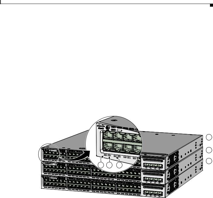
Figure 1-1 Catalyst 3650-48PD-L Switch Front Panel
3
1 2 4
ACTV
01X
12X 13X |
|
|
|
Catalyst 3650 |
48PoE+ 2X10G |
|
|
24X |
25X |
|
|
|
|
|
|
|
36X |
37X |
|
|
|
|
|
|
|
48X |
G1 |
G2 |
G3 |
TE3 G4 |
|
|
|
|
|
TE4 |
|||
|
|
|
|
|
|
||
5
6
347809
Figure 1-2 |
Catalyst 3650-24PS-L Switch Front Panel |
|||
|
|
|
|
|
1 |
Mode button |
4 |
USB Type A storage port |
|
|
|
|
|
|
2 |
Status LEDs |
|
5 |
10/100/1000 PoE+ Ethernet ports |
|
|
|
|
|
3 |
USB mini-Type B (console) port |
6 |
Uplink ports |
|
|
|
|
|
|
|
|
3 |
1 |
2 |
4 |
ACTV
|
|
|
Catalyst 3650 |
48PoE+ 2X10G |
|
|
01X |
|
|
|
|
|
|
12X |
13X |
|
|
|
|
|
|
24X |
G1 |
G2 |
G3 |
TE3 G4 |
|
|
|
|
TE4 |
|||
|
|
|
|
|
||
5
|
|
|
6 |
|
|
|
|
1 |
Mode button |
4 |
USB Type A storage port |
|
|
|
|
2 |
Status LEDs |
5 |
10/100/1000 PoE+ Ethernet ports |
|
|
|
|
3 |
USB mini-Type B (console) port |
6 |
Uplink ports |
|
|
|
|
347615
Catalyst 3650 Switch Hardware Installation Guide
|
OL-29734-01 |
1-5 |
|
|
|

Chapter 1 Product Overview
Front Panel
10/100/1000 Ethernet Ports
The 10/100/1000 Ethernet ports use RJ-45 connectors with Ethernet pinouts. The maximum cable length is 328 feet (100 meters). The 100BASE-TX and 1000BASE-T traffic requires Category 5, Category 5e, or Category 6 unshielded twisted pair (UTP) cable. The 10BASE-T traffic can use Category 3 or Category 4 UTP cable.
For information about the 10/100/1000 Ethernet port connections and specifications, see the “10/100/1000 Ethernet Port Connections” section on page 2-19 and Appendix B, “Connector and Cable Specifications.”
PoE and PoE+
The PoE+ ports use the same connectors as described in the “10/100/1000 Ethernet Ports” section on page 1-6.
These PoE+ ports provide:
•Support for IEEE 802.3af-compliant powered devices (up to 15.4 W PoE per port) and support for IEEE 802.3at-compliant powered devices (up to 30 W PoE+ per port).
•Support for Cisco-enhanced PoE.
•Support for prestandard Cisco powered devices.
•Configurable support for Cisco intelligent power management, including enhanced power negotiation, power reservation, and per-port power policing.
See Table 1-12 on page 1-18 for the power supply matrix that defines the available PoE and PoE+ power per port.
Note For information on 250-W AC power supply support on the PoE-capable switch models, refer to the
Release Notes for the Cisco Catalyst 3650 Switch on Cisco.com.
Note The output of the PoE+ circuit has been evaluated as a Limited Power Source (LPS) per IEC 60950-1.
For information about power supply modules, PoE+ port connections, and PoE+ specifications, see the “Power Supply Modules” section on page 1-17, the “PoE+ Port Connections” section on page 2-21, and Appendix B, “Connector and Cable Specifications.”
Management Ports
•Ethernet management port (see the “Ethernet Management Port” section on page 1-20)
•RJ-45 console port (EIA/TIA-232) (see the “RJ-45 Console Port” section on page 1-20)
•USB mini-Type B console port (5-pin connector)
You can connect the switch to a host such as a Windows workstation or a terminal server through the Ethernet management port, the RJ-45 console port, or the USB console port (USB mini-Type B port).
The USB console port connection uses a USB Type A to 5-pin mini-Type B cable. The USB console interface speeds are the same as the RJ-45 console interface speeds.
Catalyst 3650 Switch Hardware Installation Guide
1-6 |
OL-29734-01 |
|
|

Chapter 1 Product Overview
Front Panel
USB Mini-Type B Port
The switch provides a USB mini-Type B console connection on the front panel, and the RJ-45 console port on the switch rear panel. Console output is always active on both connectors, but console input is active on only one connector at a time, with the USB connector taking precedence over the RJ-45 connector.
Use a USB type-A-to-USB 5-pin mini-Type B cable to connect a PC or other device to the switch. The required USB cable is included in the optional accessory kit.
The connected device must include a terminal emulation application.
Windows PCs need a driver for the USB port. See the “Installing the Cisco Microsoft Windows USB Device Driver” section on page C-3 for installation instructions.
When the switch detects a valid USB connection to a powered device, input from the RJ-45 console port is immediately disabled, and input from the USB console is enabled. Removing the USB connection immediately reenables input from the RJ-45 console connection. An LED on the switch front panel (see Figure 1-4) is green when the USB console connection is enabled.
The switch provides a configurable inactivity timeout that reactivates the RJ-45 console if no input activity has occurred on the USB console for a specified time period. After the USB console has been deactivated due to a timeout, you can restore its operation by disconnecting and reconnecting the USB cable. You can disable USB console operation by using Cisco IOS commands. See the switch software configuration guide for details.
Note The 4-pin mini-Type B connectors resemble 5-pin mini-Type B connectors. They are not compatible. Use only the 5-pin mini-Type B. See Figure 1-3.
Figure 1-3 USB Mini-Type B Port
 253163
You can use the command-line interface (CLI) to configure an inactivity timeout which reactivates the RJ-45 console if the USB console has been activated and no input activity has occurred on the USB console for a specified time period.
After the USB console deactivates due to inactivity, you cannot use the CLI to reactivate it. Disconnect and reconnect the USB cable to reactivate the USB console. For information on using the CLI to configure the USB console interface, see the switch software guide.
USB Type A Port
The USB Type A interface provides access to external USB flash devices (also known as thumb drives or USB keys).
The interface supports Cisco USB flash drives with capacities from 64 MB to 1 GB.
Cisco IOS software provides standard file system access to the flash device: read, write, erase, and copy, as well as the ability to format the flash device with a FAT file system.
For more information about the switch management ports, see the switch software configuration guide and the command reference on Cisco.com and the “Connector Specifications” section on page B-1.
Catalyst 3650 Switch Hardware Installation Guide
|
OL-29734-01 |
1-7 |
|
|
|

Chapter 1 Product Overview
Front Panel
Uplink Ports
The switch supports four SFP module slots that provide uplink ports to connect to other devices. Depending upon the switch model, the uplink port support for SFP and SFP+ modules is:
•Four slots supporting only 1-Gigabit SFP modules.
•Two slots (left side) supporting only 1-Gigabit SFP modules and two slots (right side) supporting either 10-Gigabit SFP+ modules or 1-Gigabit SFP modules.
•Four slots supporting either 1-Gigabit SFP modules or 10-Gigabit SFP+ modules.
For more information, see “Catalyst 3650 Switch Models” in Table 1-1 on page 1-1. For cable specifications, see Appendix B, “Connector and Cable Specifications.”
Note If you insert an SFP+ module in an SFP module slot, the SFP+ module slot does not operate, and the switch logs an error message. SFP modules can operate in SFP+ module slots.
SFP and SFP+ Modules
The SFP and SFP+ modules provide copper or fiber-optic connections to other devices. These transceiver modules are field replaceable, and provide the uplink interfaces when installed in an SFP module slot. The SFP modules have LC connectors for fiber-optic connections or RJ-45 connectors for copper connections.
Use only Cisco SFP and SFP+ modules on the switch. For the latest information about supported SFP/SFP+ modules, refer to the Cisco Transceiver Modules Compatibility Matrix documentation at:
http://www.cisco.com/en/US/products/hw/modules/ps5455/products_device_support_tables_list.html
For information about SFP modules, see your SFP module documentation and the “Installing SFP and SFP+ Modules” section on page 2-17. For cable specifications, see Appendix B, “Connector and Cable Specifications.”
LEDs
You can use the switch LEDs to monitor switch activity and its performance. Figure 1-4 shows the switch LEDs and the Mode button that you use to select a port mode.
Catalyst 3650 Switch Hardware Installation Guide
1-8 |
OL-29734-01 |
|
|
Chapter 1 Product Overview
Front Panel
Figure 1-4 Switch Front Panel LEDs
1 |
2 |
3 |
4 |
5 |
6 |
|
|
||||
|
|
|
|||
|
|
|
|
01X
7 8
347616
1 |
STAT (status) |
5 |
PoE1 |
2 |
DUPLX (duplex) |
6 |
CONSOLE (USB mini-Type B (console) port |
|
|
|
|
3 |
SPEED |
7 |
SYST (system) |
|
|
|
|
4 |
STACK |
8 |
ACTV (active) |
|
|
|
|
1. Only switches with PoE+ ports.
The illustrations of the Catalyst 3650 switch are not intended to depict any particular color scheme. They are provided as a reference for various features and markings described within this guide.
SYST LED
Table 1-2 |
SYST LED |
|
|
|
|
Color |
|
System Status |
|
|
|
Off |
|
System is not powered on. |
|
|
|
Green |
|
System is operating normally. |
|
|
|
Blinking green |
|
Switch is running POST. |
|
|
|
Catalyst 3650 Switch Hardware Installation Guide
|
OL-29734-01 |
1-9 |
|
|
|

Chapter 1 Product Overview
Front Panel
Table 1-2 |
SYST LED (continued) |
||
|
|
|
|
Color |
|
System Status |
|
|
|
|
|
Blinking amber |
|
There is a fault with one of the following: |
|
|
|
• |
Power supply |
|
|
• |
Fan module |
|
|
|
|
Amber |
|
System is receiving power but is not functioning properly. |
|
|
|
|
|
For information on the SYST LED colors during POST, see the “Diagnosing Problems” section on page 5-1.
Port LEDs and Modes
Each Ethernet port, 1-Gigabit Ethernet module slot, and 10-Gigabit Ethernet module slot has a port LED. These port LEDs, as a group or individually, display information about the switch and about the individual ports. The port mode determines the type of information shown by the port LEDs. Table 1-3 lists the mode LEDs and their associated port modes and meanings.
To select or change a mode, press the Mode button until the desired mode is highlighted. When you change port modes, the meanings of the port LED colors also change. Table 1-4 explains how to interpret the port LED colors in different port modes.
When you press the Mode button on any switch in the switch stack, all the stack switches change to show the same selected mode. For example, if you press the Mode button on the active switch to show the SPEED LED, all the other switches in the stack also show the SPEED LED.
Table 1-3 |
Port Mode LEDs |
|
|
|
|
Mode LED |
Port Mode |
Description |
|
|
|
STAT |
Port status |
The port status. This is the default mode. |
|
|
|
SPEED |
Port speed |
The port operating speed: 10, 100 Mb/s, 1 or 10 Gb/s |
|
|
|
DUPLX |
Port duplex mode |
The port duplex mode: full duplex or half duplex. |
|
|
|
ACTV |
Active |
The active switch status. |
|
|
|
PoE1 |
PoE+ port power |
The PoE+ port status. |
1. Only switches with PoE+ ports.
|
Catalyst 3650 Switch Hardware Installation Guide |
1-10 |
OL-29734-01 |

Chapter 1 Product Overview
Front Panel
Table 1-4 |
Meaning of Switch LED Colors in Different Modes |
||
|
|
|
|
Port Mode |
|
Port LED Color |
Meaning |
|
|
|
|
STAT |
|
Off |
No link, or port was administratively shut down. |
(port status) |
|
|
|
|
Green |
Link present, no activity. |
|
|
|
||
|
|
|
|
|
|
Blinking green |
Activity. Port is sending or receiving data. |
|
|
|
|
|
|
Alternating |
Link fault. Error frames can affect connectivity, and errors such as |
|
|
green-amber |
excessive collisions, CRC errors, and alignment and jabber errors |
|
|
|
are monitored for a link-fault indication. |
|
|
|
|
|
|
Amber |
Port is blocked by Spanning Tree Protocol (STP) and is not |
|
|
|
forwarding data. |
|
|
|
After a port is reconfigured, the port LED can be amber for up to 30 |
|
|
|
seconds as STP checks the switch for possible loops. |
|
|
|
|
SPEED |
|
10/100/1000/SFP ports |
|
|
|
|
|
|
|
Off |
Port is operating at 10 Mb/s. |
|
|
|
|
|
|
Green |
Port is operating at 100 Mb/s. |
|
|
|
|
|
|
Single green |
Port is operating at 1000 Mb/s. |
|
|
flash (on for |
|
|
|
100 ms, off for |
|
|
|
1900 ms) |
|
|
|
|
|
|
|
SFP+ ports |
|
|
|
|
|
|
|
Off |
Port is not operating. |
|
|
|
|
|
|
Blinking green |
Port is operating at up to 10 Gb/s. |
|
|
|
|
DUPLX |
|
Off |
Port is operating in half duplex. |
(duplex) |
|
|
|
|
Green |
Port is operating in full duplex. |
|
|
|
||
|
|
|
|
ACTV |
|
Off |
The switch is not the active switch. |
(data active |
|
|
Note For a standalone switch, this LED is off. |
switch) |
|
|
|
|
|
|
|
|
Green |
The switch is the active switch. |
|
|
|
||
|
|
|
|
|
|
Amber |
Error during active switch election. |
|
|
|
|
|
|
Blinking green |
Switch is a standby member of a data stack and assumes active |
|
|
|
responsibilities if the current active switch fails. |
|
|
|
|
STACK |
|
Off |
No stack member corresponding to that member number. |
(stack member) |
|
|
|
|
Blinking green |
Stack member number. |
|
|
|
|
|
|
|
Green |
Member numbers of other stack member switches. |
|
|
|
|
|
|
Catalyst 3650 Switch Hardware Installation Guide |
|
|
|
|
|
|
|||
|
OL-29734-01 |
|
|
1-11 |
|
|
|
|
|
||

Chapter 1 Product Overview
Front Panel
Table 1-4 |
Meaning of Switch LED Colors in Different Modes (continued) |
|
|||||
|
|
|
|
|
|||
Port Mode |
|
Port LED Color |
Meaning |
|
|||
|
|
|
|
|
|||
PoE+1 |
|
Off |
PoE+ is off. |
|
|||
|
|
|
If the powered device is receiving power from an AC power source, |
|
|||
|
|
|
the port LED is off even if the device is connected to the switch port. |
|
|||
|
|
|
|
|
|||
|
|
Green |
PoE+ is on. The port LED is green when the switch port is providing |
|
|||
|
|
|
power. |
|
|||
|
|
|
|
|
|||
|
|
Alternating |
PoE+ is denied because providing power to the powered device will |
|
|||
|
|
green and |
exceed the switch power capacity. |
|
|||
|
|
amber |
|
|
|
|
|
|
|
|
|
|
|||
|
|
Blinking amber |
PoE+ is off due to a fault or because it has exceeded a limit set in |
|
|||
|
|
|
the switch software. |
|
|||
|
|
|
|
|
|
|
|
|
|
|
Caution PoE+ faults occur when noncompliant cabling or |
|
|||
|
|
|
|
|
|
powered devices are connected to a PoE+ port. Use only |
|
|
|
|
|
|
|
standard-compliant cabling to connect Cisco prestandard |
|
|
|
|
|
|
|
IP Phones and wireless access points or |
|
|
|
|
|
|
|
IEEE 802.3af-compliant devices to PoE+ ports. You must |
|
|
|
|
|
|
|
remove from the network any cable or device that causes |
|
|
|
|
|
|
|
a PoE+ fault. |
|
|
|
|
|
|
|
||
|
|
|
|
|
|||
|
|
Amber |
PoE+ for the port has been disabled. |
|
|||
|
|
|
Note PoE+ is enabled by default. |
|
|||
|
|
|
|
|
|
|
|
1. Only switches with PoE or PoE+ ports.
USB Console LED
The USB console LED (Figure 1-4) shows whether there is an active USB connection to the port.
Table 1-5 |
USB Console Port LED |
|
|
|
|
Color |
|
Description |
|
|
|
Off |
|
USB console is disabled. |
|
|
|
Green |
|
USB console is enabled. |
|
|
|
ACTV LED
Table 1-6 |
ACTV LED |
|
|
|
|
Color |
|
Description |
|
|
|
Off |
|
Switch is not the active switch. |
|
|
|
Green |
|
Switch is the active switch or a standalone switch. |
|
|
|
|
Catalyst 3650 Switch Hardware Installation Guide |
1-12 |
OL-29734-01 |
Chapter 1 Product Overview
Front Panel
Table 1-6 |
ACTV LED (continued) |
|
|
|
|
Color |
|
Description |
|
|
|
Amber |
|
An error occurred when the switch was selecting the active |
|
|
switch, or another type of stack error occurred. |
|
|
|
Slow blinking green |
Switch is in stack standby mode. |
|
|
|
|
STACK LED
The STACK LED shows the sequence of member switches in a stack. Up to nine switches can be members of a stack. The first nine port LEDs show the member number of a switch in a stack. Figure 1-5 shows the LEDs on the first switch, which is stack member number 1. For example, if you press the Mode button and select Stack, the LED for port 1 blinks green. The LEDs for ports 2 and 3 are solid green, as these represent the member numbers of other switches in the stack. The other port LEDs are off because there are no more members in the stack.
Figure 1-5 |
STACK LED |
ACTV
 1
1
01X |
|
|
12X |
13X |
|
|
24X |
25X |
ACTV |
|
|
01X |
|
|
12X |
13X |
|
ACTV |
24X |
25X |
01X |
|
|
12X |
13X |
|
|
24X |
25X |
|
|
|
|
Catalyst |
|
|
|
|
4 |
5 |
6 |
|
3650 48PoE+ 2X10G |
|
|||
G1 |
|
|
|
|
|
|||
|
|
48X |
G2 |
G3 |
TE3 |
G4 |
|
|
|
|
|
|
TE4 |
||||
|
|
|
|
Catalyst |
|
|
|
|
|
|
|
|
3650 48PoE+ 2X10G |
|
|||
|
36X |
37X |
|
|
|
|
|
|
|
|
48X |
G1 |
G2 |
G3 |
|
|
|
|
|
|
TE3 |
G4 |
|
|||
|
|
|
|
|
|
|||
|
|
|
|
Catalyst 3650 |
48PoE+ 2X10G |
|
||
|
36X |
37X |
|
|
|
|
|
|
|
|
48X |
G1 |
G2 |
G3 |
TE3 |
|
|
|
|
|
|
G4 |
TE4 |
|||
|
|
|
|
|
|
|||
 2
2
 3
3
347617
1 |
Stack member 1 |
4 |
LED blinks green to show that this is switch 1 in the stack. |
|
|
|
|
2 |
Stack member 2 |
5 |
LED is solid green to show that switch 2 is a stack member. |
|
|
|
|
3 |
Stack member 3 |
6 |
LED is solid green to show that switch 3 is a stack member. |
|
|
|
|
When you select the STACK LED mode, the representative STACK LEDs are green when the StackWise ports are up, and the representative STACK LEDs are amber when the ports are down.
PoE+ LED
If the PoE mode is not selected on a switch with PoE+ ports, the PoE+ LED still shows detected PoE+ problems.
|
|
Catalyst 3650 Switch Hardware Installation Guide |
|
|
|
|
|
|
|||
|
OL-29734-01 |
|
|
1-13 |
|
|
|
|
|
||

Chapter 1 Product Overview
Front Panel
Table 1-7 |
PoE+ Mode LED |
|
|
|
|
Color |
|
PoE+ Status |
|
|
|
Off |
|
PoE mode is not selected. None of the 10/100/1000 ports have been denied power |
|
|
or are in a fault condition. |
|
|
|
Green |
|
PoE mode is selected, and the port LEDs show the PoE+ status. |
|
|
|
Blinking amber |
|
PoE mode is not selected. At least one of the 10/100/1000 ports has been denied |
|
|
power, or at least one of the 10/100/1000 ports has a PoE+ fault. |
|
|
|
Uplink Ports LEDs
The four uplink ports have four status LEDs. Each port LED is labeled according to its SFP and SFP+ module status.
For SFP ports, a G(x) labeling nomenclature is used, where G = 1 Gigabit and x = the port number. The The G(x) label appears to the left of the uplink port LED.
For SFP+ ports, a TE(x) labeling nomenclature is used, where TE = 10 Gigabit and x = the port number. The TE(x) label appears to the right of the uplink port LED.
An SFP+ module ports has two labels, G(x) and TE(x), because it supports both SFP and SFP+ modules. The uplink port labeling layouts for the various switch models are:
•Four uplink port LEDs labeled G1, G2, G3, G4—This labeling represents four ports supporting SFP modules.
•Four uplink port LEDs labeled G1, G2, G3, G4 and two right side uplink ports LEDs also labeled TE3 and TE4—This labeling represents two ports (left side) supporting SFP modules and two ports (right side) supporting SFP and SFP+ modules.
•Four uplink port LEDs labeled G1, G2, G3, G4 and TE1, TE2, TE3, TE4—This labeling represents four slots supporting SFP and SFP+ modules.
Figure 1-6 shows an example of an uplink ports LED arrangement representing two SFP and two SFP+ ports (Catalyst 3650-48FD-S switch model).
|
Catalyst 3650 Switch Hardware Installation Guide |
1-14 |
OL-29734-01 |

Chapter 1 Product Overview
Rear Panel
Figure 1-6 Uplink Ports LEDs
|
|
|
Catalyst 3650 |
48PoE+ |
2X10G |
|
||
|
|
|
|
|
|
|
||
|
|
G1 |
G2 |
G3 |
TE3 |
G4 |
|
|
|
|
|
TE4 |
|||||
|
|
|
|
|||||
|
|
|
|
|
||||
|
|
|
|
|
|
|
||
|
|
|
|
|
|
|
|
|
|
|
1 |
2 |
|
3 |
|
|
4 |
|
|
|
|
|
|
|||
1 |
G1 LED |
3 |
G3, TE3 LED |
|
|
|||
2 |
G2 LED |
4 |
G4, TE4 LED |
|
|
|||
347665
Table 1-8 |
Uplink Ports LEDs |
|
||||
|
|
|
|
|||
Color |
|
Uplink Ports Link Status |
|
|||
|
|
|
|
|||
Off |
|
Link is off. |
|
|||
|
|
|
|
|||
Green |
|
Link is on, no activity. |
|
|||
|
|
|
|
|||
Blinking green |
|
Activity on a link, no faults. |
|
|||
|
|
|
|
|||
Blinking amber |
|
Link is off due to a fault or because it has exceeded a limit set in the |
|
|||
|
|
switch software. |
|
|||
|
|
|
|
|
|
|
|
|
Caution Link faults occur when noncompliant cabling is connected |
|
|||
|
|
|
|
|
to an SFP or SFP+ port. Use only standard-compliant |
|
|
|
|
|
|
cabling to connect to Cisco SFP and SFP+ ports. You must |
|
|
|
|
|
|
remove from the ports any cable or device that causes a |
|
|
|
|
|
|
link fault. |
|
|
|
|
|
|
||
|
|
|
|
|||
Amber |
|
Link for the SFP or SFP+ has been disabled. |
|
|||
|
|
|
|
|
|
|
Rear Panel
The switch rear panel includes StackWise connectors, ports, fan modules, and power supply modules. See Figure 1-7.
|
|
Catalyst 3650 Switch Hardware Installation Guide |
|
|
|
|
|
|
|||
|
OL-29734-01 |
|
|
1-15 |
|
|
|
|
|
||

Chapter 1 Product Overview
Rear Panel
Figure 1-7 Catalyst 3650 Switch Rear Panel
1 2 3 4
MGMT
1 2 3
PWR-C2-250WAC
PWR-C2-640WAC
CONSOLE |
MGMT |
4 |
5 |
4 |
5 |
4 |
6 |
7 |
8 |
6 |
7 |
8 |
347678
1 |
Ground connector |
5 |
StackWise port connector |
|
|
|
|
2 |
CONSOLE (RJ-45 console port) |
6 |
AC OK (input) status LED |
|
|
|
|
3 |
MGMT (RJ-45 10/100/1000 management |
7 |
PS OK (output) status LED |
|
port) |
|
|
|
|
|
|
4 |
Fan module |
8 |
Power supply modules (AC power supply |
|
|
|
modules shown) |
|
|
|
|
RJ-45 Console Port LED
Table 1-9 |
RJ-45 Console Port LED |
|
|
|
|
Color |
|
RJ-45 Console Port Status1 |
Off |
|
RJ-45 console is disabled. USB console is active. |
|
|
|
Green |
|
RJ-45 console is enabled. USB console is disabled. |
|
|
|
1. The USB console has priority over the RJ-45 console.
StackWise Ports
StackWise ports are used to connect switches in StackWise stacking configurations. StackWise cables are used to connect the StackWise ports for stacking. For more information on StackWise cables, see the “StackWise Cables” section on page B-5.
A StackWise adapter must be installed in the StackWise port to enable stacking. StackWise adapter blanks installed in the StackWise ports is the default setup. For more information on StackWise adapters and StackWise adapter blanks, see the “StackWise Adapters” section on page B-6 and the “StackWise Adapter Blanks” section on page B-7.
|
Catalyst 3650 Switch Hardware Installation Guide |
1-16 |
OL-29734-01 |

Chapter 1 Product Overview
Rear Panel
For Catalyst 3650 switches where stacking is specified, StackWise adapters are preinstalled in the StackWise ports, and optional StackWise cables can be ordered. When stacking is not specified, but is required, the StackWise adapter blanks must be removed and StackWise adapters installed. For more information on connecting switches for stacking see “Connecting to the StackWise Ports” section on page 2-15.
Caution Use only approved cables, and connect only to similar Cisco equipment. Equipment might be damaged if connected to nonapproved Cisco cables or equipment.
Note You cannot have a switch stack containing a mix of Catalyst 3650 and Catalyst 3850 switches.
Power Supply Modules
The 24and 48-port switches are powered through one or two internal power supply modules.
Supported power supply modules:
•PWR-C2-250WAC=
•PWR-C2-640WAC=
•PWR-C2-1025WAC=
•PWR-C2-640WDC=
The switch has two internal power supply module slots. You can use two AC modules, two DC modules, a mixed configuration of one AC and one DC power supply module, or one power supply module and a blank cover. The switch can operate with either one or two active power supply modules.
Table 1-1 shows the default power supply modules that ship with each switch model. All power supply modules (except the blank covers) have internal fans. All switches ship with a blank cover in the second power supply slot if switches are configured with only one power supply.
Caution Do not operate the switch with one power supply module slot empty. For proper chassis cooling, both power supply module slots must be populated, or with either a power supply or a blank cover.
The 250-W and 640-W AC power supply modules are autoranging units that support input voltages between 100 and 240 VAC. The 1025-W power supply module is an autoranging unit that supports input voltages between 115 and 240 VAC. The 640-W DC power supply module supports input voltages between -40 and -60 VDC.
Note For information on 250-W AC power supply support on the PoE-capable switch models, refer to the
Release Notes for the Cisco Catalyst 3650 Switch on Cisco.com.
Each AC power supply module has a power cord for connection to an AC power outlet. The 1025-W and 640-W modules use a 16-AWG cord (only North America). All other modules use an 18-AWG cord. The DC-power supply module must be wired to a DC-power source.
Table 1-10, Table 1-11, and Table 1-12 show the PoE available and PoE requirements for Catalyst 3650 switches.
|
|
Catalyst 3650 Switch Hardware Installation Guide |
|
|
|
|
|
|
|||
|
OL-29734-01 |
|
|
1-17 |
|
|
|
|
|
||

Chapter 1 Product Overview
Rear Panel
Table 1-10 |
Available PoE with AC Power Supply |
|
|
|
|
|
|
|
|
Models |
|
Default Power Supply |
Available PoE Power |
|
|
|
|
|
|
24-port data switch |
PWR-C2-250WAC= |
— |
||
|
|
|
|
|
48-port data switch |
|
|
|
|
|
|
|
|
|
24-port PoE switch |
PWR-C2-640WAC |
390 W |
||
|
|
|
|
|
48-port PoE switch |
|
|
|
|
|
|
|
|
|
48-port full PoE switch |
PWR-C2-1025WAC |
775 W |
||
|
|
|
|
|
Table 1-11 |
Available PoE with DC Power Supply1 |
|
|
|
|
|
|
|
|
Models |
|
Number of Power Supplies |
Available PoE Power |
|
|
|
|
|
|
24-port PoE switch |
1 |
390 W |
||
|
|
|
|
|
|
|
2 |
780 W |
|
|
|
|
|
|
48-port PoE switch |
1 |
390 W |
||
|
|
|
|
|
|
|
2 |
780 W |
|
|
|
|
|
|
1. The 640-W DC (PWR-C2-640WDC) power supply is the only DC module.
Table 1-12 |
Switch Power Supply Requirements for PoE and PoE+ |
||||
|
|
|
|
||
PoE Option |
|
24-Port Switch |
48-Port Switch1 |
||
PoE (up to 15.4 per |
(1) 640-W |
Power supply combinations: |
|||
port) |
|
|
• |
(1) |
1025-W |
|
|
|
|||
|
|
|
• |
(1) |
640-W + (1) 640-W |
|
|
|
|||
PoE+ (up to 30 W per |
Power supply combinations: |
Power supply combinations: |
|||
ports |
|
• (1) 1025-W |
• |
(2) |
1025-W |
|
|
||||
|
|
• (1) 640-W + (1) 640-W |
|
|
|
|
|
|
|
|
|
1. A 48-port switch with one 640-W power supply provides up to 390 W of PoE to all ports.
The power supply modules have two status LEDs.
Table 1-13 |
Switch Power Supply Module LEDs |
|
|
|
|
|
|
||
AC-Power Supply Module LEDs |
|
|
||
|
|
|
|
|
AC OK |
|
Description |
PS OK |
Description |
|
|
|
|
|
Off |
|
No AC input power. |
Off |
Output is disabled, or input is |
|
|
|
|
outside operating range (AC LED |
|
|
|
|
is off). |
|
|
|
|
|
Green |
|
AC input power present. |
Green |
Power output to switch active. |
|
|
|
|
|
|
|
|
Red |
Output has failed. |
|
|
|
|
|
|
Catalyst 3650 Switch Hardware Installation Guide |
1-18 |
OL-29734-01 |
Chapter 1 Product Overview
Rear Panel
Table 1-13 |
Switch Power Supply Module LEDs (continued) |
|
||
|
|
|
||
DC-Power Supply Module LEDs |
|
|
||
|
|
|
|
|
DC OK |
|
Description |
PS OK |
Description |
|
|
|
|
|
Off |
|
No DC input power. |
Off |
Output is disabled, or input is |
|
|
|
|
outside operating range (DC LED |
|
|
|
|
is off). |
|
|
|
|
|
Green |
|
DC input power present. |
Green |
Power output to switch active. |
|
|
|
|
|
|
|
|
Red |
Output has failed. |
|
|
|
|
|
For information about replacing a power supply module, wiring a DC power supply module, and module specifications, see Chapter 3, “Power Supply Installation,” and Appendix A, “Technical Specifications.”
Fan Modules
The switch has three internal hot-swappable 12-V fan modules. The air circulation system consists of the fan modules and the power supply modules. The airflow patterns vary depending on the power supply configuration.
Figure 1-8 shows the airflow patterns for the 24and 48-port switches. The blue arrow shows cool air flow, and the red arrow shows warm air flow. When the fan modules are operating properly, a green LED is on at the top left corner of the fan assembly (viewed from the rear). If the fan fails, the LED turns to amber. The switch can operate with two operational fans, but the failed fan should be replaced as soon as possible to avoid a service interruption due to a second fan fault.
Note Three fans are required for proper cooling.
Table 1-14 Switch Fan Module
Fan Module |
|
Description |
|
|
|
|
|
FAN-T1= |
|
Fan module |
|
|
|
|
|
Figure 1-8 |
24and 48-Port Switch Airflow Patterns |
||
ACTV
01X
12X |
13X |
Catalyst 3650 |
48PoE+ 4X1G |
|
24X |
25X |
36X |
37X |
48X
347812
For information about installing a fan module and fan specifications, see Chapter 4, “Installing the Fan,” and Appendix A, “Technical Specifications.”
|
|
Catalyst 3650 Switch Hardware Installation Guide |
|
|
|
|
|
|
|||
|
OL-29734-01 |
|
|
1-19 |
|
|
|
|
|
||

Chapter 1 Product Overview
Management Options
Management Ports
Ethernet Management Port
You can connect the switch to a host such as a Windows workstation or a terminal server through the 10/100/1000 Ethernet management port or one of the console ports (see Figure 1-7). The 10/100/1000 Ethernet management port is a VPN routing/forwarding (VRF) interface and uses a RJ-45 crossover or straight-through cable.
Table 1-15 shows the Ethernet management port LED colors and their meanings.
Table 1-15 |
Ethernet Management Port LED |
|
|
|
|
Color |
|
Description |
|
|
|
Green |
|
Link up but no activity. |
|
|
|
Blinking green |
|
Link up and activity. |
|
|
|
Off |
|
Link down. |
|
|
|
RJ-45 Console Port
The RJ-45 console port connection uses the supplied RJ-45-to-DB-9 female cable.
Table 1-16 shows the RJ-45 console port LED colors and their meanings.
Table 1-16 |
RJ-45 Console LEDs |
|
|
Color |
Description |
|
|
Green |
RJ-45 console port is active. |
|
|
Off |
The port is not active. |
|
|
Management Options
•Configuration Wizard
The Configuration Wizard is a Web-based controller user interface (UI) that lets you complete the initial wireless configuration after you configure the IP address, local username, and password or authorization using the authentication server. Using the Web UI, you can configure the controller, WLAN, and radios for all initial operations, establish management parameters, set security policies, access software management commands, configure system logs, and other tasks.
For more information on using the Configuration Wizard, see the switch software configuration guide on Cisco.com.
•Cisco Network Assistant
Cisco Network Assistant is a PC-based network management GUI application for LANs. You can use the GUI to configure and manage switch clusters or standalone switches. Cisco Network Assistant is available at no cost and can be downloaded from this URL:
http://www.cisco.com/pcgi-bin/tablebuild.pl/NetworkAssistant
|
Catalyst 3650 Switch Hardware Installation Guide |
1-20 |
OL-29734-01 |

Chapter 1 Product Overview
Management Options
For information on starting the Network Assistant application, see the Getting Started with Cisco Network Assistant guide on Cisco.com.
•Device Manager
You can use Device Manager, which is in the switch memory, to manage individual and standalone switches. This web interface offers quick configuration and monitoring. You can access Device Manager from anywhere in your network through a web browser. For more information, see the getting started guide and the Device Manager online help.
•Cisco IOS CLI
You can configure and monitor the switch and switch cluster members from the CLI. You can access the CLI by connecting your management station directly to the switch console port or by using Telnet from a remote management station. See the switch command reference on Cisco.com for more information.
•Cisco Prime Infrastructure
Cisco Prime Infrastructure combines the wireless functionality of Cisco Prime Network Control System (NCS) and the wired functionality of Cisco Prime LAN Management Solution (LMS), with application performance monitoring and troubleshooting capabilities of Cisco Prime Assurance Manager. For more information, see the Cisco Prime Infrastructure documentation on Cisco.com.
http://www.cisco.com/en/US/products/ps12239/index.html
Network Configurations
See the switch software configuration guide on Cisco.com for network configuration concepts and examples of using the switch to create dedicated network segments and interconnecting the segments through Gigabit Ethernet connections.
|
|
Catalyst 3650 Switch Hardware Installation Guide |
|
|
|
|
|
|
|||
|
OL-29734-01 |
|
|
1-21 |
|
|
|
|
|
||

Chapter 1 Product Overview
Management Options
|
Catalyst 3650 Switch Hardware Installation Guide |
1-22 |
OL-29734-01 |

C H A P T E R 2
Switch Installation
This chapter describes how to install and connect a Catalyst 3650 switch. It also includes planning and cabling considerations for stacking switches. Read the topics and perform the procedures in this order:
•Preparing for Installation, page 2-1
•Planning a Switch Data Stack, page 2-4
•Installing the Switch, page 2-9
•Connecting to the StackWise Ports, page 2-15
•Connecting Devices to the Ethernet Ports, page 2-19
•Where to Go Next, page 2-22
For initial switch setup, how to assign the switch IP address, and for powering information, see the switch getting started guide on Cisco.com.
Preparing for Installation
•Safety Warnings, page 2-1
•Installation Guidelines, page 2-3
•Tools and Equipment, page 2-4
Safety Warnings
This section includes the basic installation caution and warning statements. Translations of the warning statements appear in the Regulatory Compliance and Safety Information for the Catalyst 3650 Switch document available at Cisco.com. Read this section before you start the installation procedure.
Warning Before working on equipment that is connected to power lines, remove jewelry (including rings, necklaces, and watches). Metal objects will heat up when connected to power and ground and can cause serious burns or weld the metal object to the terminals. Statement 43
Warning Do not stack the chassis on any other equipment. If the chassis falls, it can cause severe bodily injury and equipment damage. Statement 48
Catalyst 3650 Switch Hardware Installation Guide
|
OL-29734-01 |
2-1 |
|
|
|

Chapter 2 Switch Installation
Preparing for Installation
Warning Ethernet cables must be shielded when used in a central office environment. Statement 171
Warning Voice over IP (VoIP) service and the emergency calling service do not function if power fails or is disrupted. After power is restored, you might have to reset or reconfigure equipment to regain access to VoIP and the emergency calling service. In the USA, this emergency number is 911. You need to be aware of the emergency number in your country. Statement 361
Warning Do not work on the system or connect or disconnect cables during periods of lightning activity.
Statement 1001
Warning Read the installation instructions before connecting the system to the power source. Statement 1004
Warning This unit is intended for installation in restricted access areas. A restricted access area can be accessed only through the use of a special tool, lock and key, or other means of security.
Statement 1017
Warning The plug-socket combination must be accessible at all times, because it serves as the main disconnecting device. Statement 1019
Warning Use copper conductors only. Statement 1025
Warning This unit might have more than one power supply connection. All connections must be removed to de-energize the unit. Statement 1028
Warning Only trained and qualified personnel should be allowed to install, replace, or service this equipment.
Statement 1030
Warning Ultimate disposal of this product should be handled according to all national laws and regulations.
Statement 1040
Warning For connections outside the building where the equipment is installed, the following ports must be connected through an approved network termination unit with integral circuit protection: 10/100/1000 Ethernet. Statement 1044
Catalyst 3650 Switch Hardware Installation Guide
2-2 |
OL-29734-01 |
|
|

Chapter 2 Switch Installation
Preparing for Installation
Warning To prevent the system from overheating, do not operate it in an area that exceeds the maximum recommended ambient temperature of:
113°F (45°C) Statement 1047
Warning No user-serviceable parts inside. Do not open. Statement 1073
Warning Installation of the equipment must comply with local and national electrical codes. Statement 1074
Warning To prevent airflow restriction, allow clearance around the ventilation openings to be at least: 3 in. (7.6 cm) Statement 1076
Note The grounding architecture of this product is DC-isolated (DC-I).
Installation Guidelines
Before installing the switch, verify that these guidelines are met:
•For the clearance to the front and rear panels, make sure that
–Front-panel indicators can be easily read.
–Clearance is at least 4.4 in. (11.1 cm) from switch rear panel.
–Access to ports is sufficient for unrestricted cabling.
–AC power cord can reach from the AC power outlet to the connector on the switch rear panel.
–The SFP or SFP+ module minimum bend radius and connector length is met. See the SFP or SFP+ module documentation for more information.
•For switches with the optional 1025-W power-supply module (PWR-C2-1025WAC=), first rack-mount the switch before installing the power-supply module.
•Make sure power-supply modules and fan modules are securely inserted in the chassis before moving the switch.
•When connecting or disconnecting the power cord on a switch that is installed above or below a 1025-W power supply-equipped switch, you might need to remove the module from the switch to access the power cord.
•Cabling is away from sources of electrical noise, such as radios, power lines, and fluorescent lighting fixtures. Make sure that the cabling is safely away from other devices that might damage the cables.
•For copper connections on Ethernet ports, cable lengths from the switch to connected devices can be up to 328 feet (100 meters).
•For cable requirements for SFP+ module connections, see the “Cable and Adapter Specifications” section on page B-5. Each port must match the wave-length specifications on the other end of the cable, and the cable must not exceed the maximum cable length.
Catalyst 3650 Switch Hardware Installation Guide
|
OL-29734-01 |
2-3 |
|
|
|

Chapter 2 Switch Installation
Planning a Switch Data Stack
•Operating environment is within the ranges listed in Appendix A, “Technical Specifications.”
•Airflow around the switch and through the vents is unrestricted.
•Temperature around the unit does not exceed 113°F (45°C). If the switch is installed in a closed or multirack assembly, the temperature around it might be greater than normal room temperature.
•Cisco Ethernet switches are equipped with cooling mechanisms, such as fans and blowers. However, these fans and blowers can draw dust and other particles, causing contaminant buildup inside the chassis, which can result in system malfunction. You must install this equipment in an environment as free from dust and foreign conductive material (such as metal flakes from construction activities) as is possible.
Tools and Equipment
Obtain these necessary tools and equipment:
•A number-2 Phillips screwdriver to rack-mount the switch.
•A Torx T15 screwdriver, or the Torx T15 key that ships with StackWise upgrade kits, to install the StackWise adapter.
Verifying Switch Operation
Before you install the switch in a rack, or on a table or shelf, you should power on the switch and verify that the switch passes POST. See the “Running Express Setup” section in the getting started guide for the steps required to connect a PC to the switch and to run Express Setup.
Powering Off the Switch
After a successful POST, disconnect the power cord from the switch. Install the switch in a rack, on a table, or on a shelf as described in the Chapter 2, “Installing the Switch,” section.
Planning a Switch Data Stack
Catalyst 3650 switches can share bandwidth by using data stacking.
•Switch Stacking Guidelines, page 2-5
•Data Stack Cabling Configurations, page 2-5
•Data Stack Bandwidth and Partitioning Examples, page 2-6
•Power-On Sequence for Switch Data Stacks, page 2-7
•Changes to Switch Stack Membership, page 2-8
Catalyst 3650 Switch Hardware Installation Guide
2-4 |
OL-29734-01 |
|
|

Chapter 2 Switch Installation
Planning a Switch Data Stack
Switch Stacking Guidelines
For general concepts and management procedures for switch stacks, see the switch software configuration guide on Cisco.com.
A StackWise adapter must be installed in the stacking port to enable stacking. The StackWise cable connects to the StackWise adapter in the stacking port. For switches ordered with stacking, the StackWise adapters are pre-installed. If the switch is not ordered with stacking, the adapters must be ordered separately and installed.
Before connecting the switches in a stack, observe these stacking guidelines:
•Size of the switch and any optional power-supply module. The 1025-W power-supply module is longer than the other modules. Stacking switches with the same power-supply modules together makes it easier to cable the switches. For switch dimensions, see Appendix A, “Technical Specifications.”
•Length of StackWise cable. Depending on the configurations that you have, you might need different-sized StackWise cables. If you do not specify the length of the StackWise cable, the 0.5-meter cable is supplied. If you need the 1-meter cable or the 3-meter cable, you can order it from your Cisco supplier. For cable part numbers, see the “StackWise Cables” section on page B-5. The “Data Stack Cabling Configurations” section on page 2-5 provides examples of recommended configurations.
•Minimum bend radius and coiled diameter for StackWise cables. Cisco recommends a minimum bend radius and coiled diameter for each StackWise cable. For more information, see Table B-1 in the “StackWise Cables Minimum Bend Radius and Coiled Diameter” section on page B-6.
•Data stacks can be created with up to nine switches in a stack.
Note You cannot have a switch stack containing a mix of Catalyst 3650 and Catalyst 3850 switches.
Data Stack Cabling Configurations
Figure 2-1 is an example of a recommended configuration that uses the supplied 0.5-meter StackWise cable. In this example, the switches are stacked in a vertical rack or on a table. This configuration provides redundant connections.
Catalyst 3650 Switch Hardware Installation Guide
|
OL-29734-01 |
2-5 |
|
|
|
Loading...