


 Loading...
Cisco 3200 Series Router Hardware
Reference
August 2008
Americas Headquarters
Cisco Systems, Inc. 170 West Tasman Drive
San Jose, CA 95134-1706 USA http://www.cisco.com Tel: 408 526-4000
800 553-NETS (6387) Fax: 408 527-0883
Text Part Number: OL-5816-10
THE SPECIFICATIONS AND INFORMATION REGARDING THE PRODUCTS IN THIS MANUAL ARE SUBJECT TO CHANGE WITHOUT NOTICE. ALL STATEMENTS, INFORMATION, AND RECOMMENDATIONS IN THIS MANUAL ARE BELIEVED TO BE ACCURATE BUT ARE PRESENTED WITHOUT WARRANTY OF ANY KIND, EXPRESS OR IMPLIED. USERS MUST TAKE FULL RESPONSIBILITY FOR THEIR APPLICATION OF ANY PRODUCTS.
THE SOFTWARE LICENSE AND LIMITED WARRANTY FOR THE ACCOMPANYING PRODUCT ARE SET FORTH IN THE INFORMATION PACKET THAT SHIPPED WITH THE PRODUCT AND ARE INCORPORATED HEREIN BY THIS REFERENCE. IF YOU ARE UNABLE TO LOCATE THE SOFTWARE LICENSE OR LIMITED WARRANTY, CONTACT YOUR CISCO REPRESENTATIVE FOR A COPY.
The following information is for FCC compliance of Class A devices: This equipment has been tested and found to comply with the limits for a Class A digital device, pursuant to part 15 of the FCC rules. These limits are designed to provide reasonable protection against harmful interference when the equipment is operated in a commercial environment. This equipment generates, uses, and can radiate radio-frequency energy and, if not installed and used in accordance with the instruction manual, may cause harmful interference to radio communications. Operation of this equipment in a residential area is likely to cause harmful interference, in which case users will be required to correct the interference at their own expense.
The following information is for FCC compliance of Class B devices: The equipment described in this manual generates and may radiate radio-frequency energy. If it is not installed in accordance with Cisco’s installation instructions, it may cause interference with radio and television reception. This equipment has been tested and found to comply with the limits for a Class B digital device in accordance with the specifications in part 15 of the FCC rules. These specifications are designed to provide reasonable protection against such interference in a residential installation. However, there is no guarantee that interference will not occur in a particular installation.
Modifying the equipment without Cisco’s written authorization may result in the equipment no longer complying with FCC requirements for Class A or Class B digital devices. In that event, your right to use the equipment may be limited by FCC regulations, and you may be required to correct any interference to radio or television communications at your own expense.
You can determine whether your equipment is causing interference by turning it off. If the interference stops, it was probably caused by the Cisco equipment or one of its peripheral devices. If the equipment causes interference to radio or television reception, try to correct the interference by using one or more of the following measures:
•Turn the television or radio antenna until the interference stops.
•Move the equipment to one side or the other of the television or radio.
•Move the equipment farther away from the television or radio.
•Plug the equipment into an outlet that is on a different circuit from the television or radio. (That is, make certain the equipment and the television or radio are on circuits controlled by different circuit breakers or fuses.)
Modifications to this product not authorized by Cisco Systems, Inc. could void the FCC approval and negate your authority to operate the product.
The Cisco implementation of TCP header compression is an adaptation of a program developed by the University of California, Berkeley (UCB) as part of UCB’s public domain version of the UNIX operating system. All rights reserved. Copyright © 1981, Regents of the University of California.
NOTWITHSTANDING ANY OTHER WARRANTY HEREIN, ALL DOCUMENT FILES AND SOFTWARE OF THESE SUPPLIERS ARE PROVIDED “AS IS” WITH ALL FAULTS. CISCO AND THE ABOVE-NAMED SUPPLIERS DISCLAIM ALL WARRANTIES, EXPRESSED OR IMPLIED, INCLUDING, WITHOUT LIMITATION, THOSE OF MERCHANTABILITY, FITNESS FOR A PARTICULAR PURPOSE AND NONINFRINGEMENT OR ARISING FROM A COURSE OF DEALING, USAGE, OR TRADE PRACTICE.
IN NO EVENT SHALL CISCO OR ITS SUPPLIERS BE LIABLE FOR ANY INDIRECT, SPECIAL, CONSEQUENTIAL, OR INCIDENTAL DAMAGES, INCLUDING, WITHOUT LIMITATION, LOST PROFITS OR LOSS OR DAMAGE TO DATA ARISING OUT OF THE USE OR INABILITY TO USE THIS MANUAL, EVEN IF CISCO OR ITS SUPPLIERS HAVE BEEN ADVISED OF THE POSSIBILITY OF SUCH DAMAGES.
CCDE, CCENT, Cisco Eos, Cisco Lumin, Cisco Nexus, Cisco StadiumVision, Cisco TelePresence, the Cisco logo, DCE, and Welcome to the Human Network are trademarks; Changing the Way We Work, Live, Play, and Learn and Cisco Store are service marks; and Access Registrar, Aironet, AsyncOS, Bringing the Meeting To You, Catalyst, CCDA, CCDP, CCIE, CCIP, CCNA, CCNP, CCSP, CCVP, Cisco, the Cisco Certified Internetwork Expert logo, Cisco IOS, Cisco Press, Cisco Systems, Cisco Systems Capital, the Cisco Systems logo, Cisco Unity, Collaboration Without Limitation, EtherFast, EtherSwitch, Event Center, Fast Step, Follow Me Browsing, FormShare, GigaDrive, HomeLink, Internet Quotient, IOS, iPhone, iQ Expertise, the iQ logo, iQ Net Readiness Scorecard, iQuick Study, IronPort, the IronPort logo, LightStream, Linksys, MediaTone, MeetingPlace, MeetingPlace Chime Sound, MGX, Networkers, Networking Academy, Network Registrar, PCNow, PIX, PowerPanels, ProConnect, ScriptShare, SenderBase, SMARTnet, Spectrum Expert, StackWise, The Fastest Way to Increase Your Internet Quotient, TransPath, WebEx, and the WebEx logo are registered trademarks of Cisco Systems, Inc. and/or its affiliates in the United States and certain other countries.
All other trademarks mentioned in this document or Website are the property of their respective owners. The use of the word partner does not imply a partnership relationship between Cisco and any other company. (0807R)
Any Internet Protocol (IP) addresses used in this document are not intended to be actual addresses. Any examples, command display output, and figures included in the document are shown for illustrative purposes only. Any use of actual IP addresses in illustrative content is unintentional and coincidental.
Cisco 3200 Series Router Hardware Reference
© 2008 Cisco Systems, Inc. All rights reserved.

|
|
|
|
|
|
|
|
|
|
C O N T E N T S |
|||||
|
|
|
Introduction to the Cisco 3200 Series Routers |
vii |
|
|
|
|
|
||||||
|
|
|
Audience and Scope |
viii |
|
|
|
|
|
|
|
|
|
|
|
|
|
|
Related Documentation |
viii |
|
|
|
|
|
|
|
|
|
||
|
|
|
Conventions |
ix |
|
|
|
|
|
|
|
|
|
|
|
|
|
Cisco 3200 Rugged Enclosures |
|
|
|
|
|
|
|
|
|
||||
C H A P T E R |
1 |
1-1 |
|
|
|
|
|
|
|
|
|||||
|
|
|
Cisco 3270 Rugged Enclosure |
1-3 |
|
|
|
|
|
|
|
|
|||
|
|
|
Cisco 3270 Router Card Stack |
1-4 |
|
|
|
|
|
|
|
||||
|
|
|
Cisco 3230 Rugged Enclosure |
1-5 |
|
|
|
|
|
|
|
|
|||
|
|
|
Cisco 3230 Router Card Stack |
1-6 |
|
|
|
|
|
|
|
||||
|
|
|
Rugged Enclosure End Caps |
1-7 |
|
|
|
|
|
|
|
|
|||
|
|
|
Antenna End Cap |
1-7 |
|
|
|
|
|
|
|
|
|
||
|
|
|
I/O End Caps for the Cisco 3200 Rugged Enclosures |
1-8 |
|
|
|
|
|||||||
|
|
|
End Cap Fast Ethernet and WMIC Console Ports |
1-8 |
|
|
|
|
|||||||
|
|
|
Cisco 3270 Router I/O End Cap |
1-9 |
|
|
|
|
|
|
|||||
|
|
|
Cisco 3230 Router I/O End Cap |
1-12 |
|
|
|
|
|
|
|||||
|
|
|
Protective End Cap Cover |
1-13 |
|
|
|
|
|
|
|
|
|||
|
|
|
I/O End Cap Port Signals |
1-15 |
|
|
|
|
|
|
|
|
|||
|
|
|
Gigabit Ethernet Signal Limitations |
1-15 |
|
|
|
|
|
|
|||||
|
|
|
Fast Ethernet Signals |
1-15 |
|
|
|
|
|
|
|
|
|||
|
|
|
Fast Ethernet Port Cabling for the Cisco 3250 and Cisco 3230 Routers 1-16 |
||||||||||||
|
|
|
Console Port Signals |
1-17 |
|
|
|
|
|
|
|
|
|||
|
|
|
AUX Port Signals |
1-17 |
|
|
|
|
|
|
|
|
|
||
|
|
|
Cisco 3200 Rugged Enclosure LED Indications |
1-18 |
|
|
|
|
|
||||||
|
|
|
Cisco 3270 Rugged Enclosure I/O End Cap LED Indications |
1-18 |
|
|
|
||||||||
|
|
|
Cisco 3230 Rugged Enclosure I/O End Cap LED Indications |
1-19 |
|
|
|
||||||||
|
|
|
WMIC Console LEDs |
1-19 |
|
|
|
|
|
|
|
|
|||
|
|
|
Thermal Plates |
1-20 |
|
|
|
|
|
|
|
|
|
|
|
|
|
|
Mounting Brackets |
1-21 |
|
|
|
|
|
|
|
|
|
|
|
|
|
Cisco 3270 Rugged Router Card |
|
|
|
|
|
|
|
|
|
||||
C H A P T E R |
2 |
2-1 |
|
|
|
|
|
|
|
|
|||||
|
|
|
Cisco 3270 Rugged Router Card Component Systems 2-2 |
|
|
|
|
|
|||||||
|
|
|
|
|
|
|
|
|
|
Cisco 3200 Series Router Hardware Reference |
|
|
|
||
|
|
|
|
|
|
|
|
|
|
|
|||||
|
OL-5816-10 |
|
|
|
|
|
|
|
|
|
|
|
3 |
|
|
|
|
|
|
|
|
|
|
|
|
|
|
|
|||

Contents
|
|
|
|
|
Cisco 3270 Rugged Router Card Power Requirements |
2-4 |
|
|||||||
|
|
|
|
|
Power Connections (AUX) |
2-4 |
|
|
|
|
||||
|
|
|
|
|
Hardware Encryption Processor |
2-4 |
|
|
|
|
||||
|
|
|
|
|
Ethernet Port Speed and Duplex Mode |
2-6 |
|
|
||||||
|
|
|
|
|
Cisco 3270 Rugged Router Card Encryption Module 2-7 |
|
|
|||||||
|
|
|
|
|
Security Engine Features |
2-7 |
|
|
|
|
|
|||
|
|
|
|
|
Temperature Sensor 2-8 |
|
|
|
|
|
|
|
||
|
|
|
|
|
Cisco 3270 Rugged Router Card MAC Address Allocation |
2-8 |
|
|||||||
|
|
|
Mobile Access Router Card |
|
|
|
|
|
|
|
||||
C H A P T E R |
3 |
|
3-1 |
|
|
|
|
|
|
|||||
|
|
|
|
|
MARC Component Systems |
3-2 |
|
|
|
|
|
|||
|
|
|
|
|
MARC Power Requirements |
3-3 |
|
|
|
|
||||
|
|
|
|
|
MARC Router Signals |
3-3 |
|
|
|
|
|
|
||
|
|
|
|
|
Fast Ethernet Signals on the MARC |
3-3 |
|
|
||||||
|
|
|
|
|
Console and Auxiliary Signals |
3-4 |
|
|
|
|||||
|
|
|
Fast Ethernet Switch Mobile Interface Card |
|
|
|
||||||||
C H A P T E R |
4 |
|
4-1 |
|
|
|||||||||
|
|
|
|
|
Autonegotiation and Auto-MDI/MDIX |
4-2 |
|
|
|
|||||
|
|
|
|
|
MAC Address Allocation |
|
4-2 |
|
|
|
|
|
|
|
|
|
|
|
|
FESMIC Component Systems 4-3 |
|
|
|
|
|
||||
|
|
|
|
|
Signals for the FESMIC |
4-4 |
|
|
|
|
|
|||
|
|
|
|
|
FESMIC Rotary Switch Positions |
4-5 |
|
|
|
|||||
|
|
|
Serial Mobile Interface Card |
|
|
|
|
|
|
|||||
C H A P T E R |
5 |
|
5-1 |
|
|
|
|
|
||||||
|
|
|
|
|
SMIC Component Systems |
5-2 |
|
|
|
|
|
|||
|
|
|
|
|
Signals for the SMIC |
|
5-3 |
|
|
|
|
|
|
|
|
|
|
|
|
4-Port SMIC Rotary Switch Positions |
5-3 |
|
|
||||||
|
|
|
|
|
2-port SMIC Rotary Switch Positions |
5-4 |
|
|
||||||
|
|
|
|
|
SMIC LED Signals |
5-4 |
|
|
|
|
|
|
||
|
|
|
|
|
SMIC Power Consumption |
5-5 |
|
|
|
|
|
|
||
|
|
|
Wireless Mobile Interface Cards |
|
|
|
|
|
||||||
C H A P T E R |
6 |
|
6-1 |
|
|
|
|
|||||||
|
|
|
|
|
WMIC Component Systems |
6-1 |
|
|
|
|
|
|||
|
|
|
|
|
Antenna Connector |
6-2 |
|
|
|
|
|
|
||
|
|
|
|
|
WMIC Console and Fast Ethernet Ports |
6-2 |
|
|
|
|||||
|
|
|
|
|
Fast Ethernet Signals on the WMIC |
6-3 |
|
|
|
|||||
|
|
|
|
|
LED Behavior |
6-4 |
|
|
|
|
|
|
|
|
|
|
|
|
|
Key Features |
6-5 |
|
|
|
|
|
|
|
|
|
|
|
|
Cisco 3200 Series Router Hardware Reference |
|
|
|
|
|
|
|
|
||
|
|
|
|
|
|
|
|
|
|
|
|
|||
|
4 |
|
|
|
|
|
|
|
|
|
|
|
OL-5816-10 |
|
|
|
|
|
|
|
|
|
|
|
|
|
|
||

Contents
MAC Address Allocation |
6-7 |
|
|
|
|||
WMIC Power Requirement |
6-7 |
|
|
|
|||
Mean Time Between Failure |
6-7 |
|
|
|
|||
Differences Between WMICs |
6-7 |
|
|
|
|||
2.4-GHz (802.11b/g) WMIC Features |
6-10 |
|
|||||
Universal Workgroup Bridge Limitations |
6-12 |
||||||
4.9-GHz (Public Safety) WMIC Features |
6-13 |
||||||
4.9-GHz Channels |
6-13 |
|
|
|
|||
Throughput |
6-14 |
|
|
|
|
|
|
Modulation |
6-14 |
|
|
|
|
|
|
Receive Sensitivity |
6-15 |
|
|
|
|||
5.0-GHz (802.11h) Radio Features |
6-15 |
|
|||||
5.0-GHz (802.11h) Channels |
6-15 |
|
|
||||
Throughput |
6-16 |
|
|
|
|
|
|
Modulation |
6-16 |
|
|
|
|
|
|
Receive Sensitivity |
6-16 |
|
|
|
|||
Transmit Sensitivity |
6-17 |
|
|
|
|||
Related Documentation |
6-17 |
|
|
|
|
|
|
Replacing SFP Modules into SFP Module Slots |
B-2 |
||||||
Diagnosing SFP Problems |
|
B-3 |
|
|
|
||
Error Messages |
B-4 |
|
|
|
|
|
|
Cisco 3200 Series Router Hardware Reference
|
OL-5816-10 |
5 |
|
|
|

Contents
Cisco 3200 Series Router Hardware Reference
6 |
OL-5816-10 |
|
|

Introduction to the Cisco 3200 Series Routers
The Cisco 3200 Series routers provides industry-standard network software features that run on ruggedized hardware, suitable for harsh environments. A router includes a combination of mobile interface cards and a Cisco 3200 Rugged Enclosure. The following major components are available from Cisco:
•Cisco 3200 Rugged Enclosures
•Cisco 3270 Rugged Router card
•Mobile Access Router Card (MARC)
•Fast Ethernet Switch Mobile Interface Cards (FESMICs)
•Serial Mobile Interface Cards (SMICs)
•Wireless Mobile Interface Cards (WMICs)
This document describes the Cisco cards and the enclosure solutions that are used to assemble
Cisco 3200 Series routers. A router can be purchased as a complete unit or purchased in part from Cisco and assembled by a qualified system integrator (SI) as a custom solution. For example, a qualified SI might assemble cards into a custom enclosure to suit a particular environment. Custom solutions based on Cisco cards must include a power source, cables, and an enclosure. For information about the specific hardware configuration of your router, contact your SI.
The following chapters provide information that you need for understanding the physical components of a completed Cisco 3200 Series router. This document is not intended to cover assembly or repair instructions.
Chapter 1, “Cisco 3270 Rugged Enclosure,” describes the enclosures that house the Cisco 3200 Series routers.
Chapter 2, “Cisco 3270 Rugged Router Card,” describes the Cisco 3270 Rugged Router card layout.
Chapter 3, “Mobile Access Router Card,” describes the MARC layout.
Chapter 4, “Fast Ethernet Switch Mobile Interface Card,” describes the FESMIC layout, ports, and buses.
Chapter 5, “Serial Mobile Interface Card,” describes the SMIC layout, ports, and buses.
Chapter 6, “Wireless Mobile Interface Cards,” describes the WMIC layout, ports, and buses.
Appendix A, “Smart Serial Port External Seal,” describes how to seal the Smart Serial port.
Appendix B, “SFP Module Replacement,” describes how to install and remove small form-factor pluggable (SFP) modules on the Cisco 3270 Rugged Router card.
Cisco 3200 Series Router Hardware Reference
|
OL-5816-10 |
7 |
|
|
|

Audience and Scope
The audience for this document is the system administrator (SA), the SI, and the system engineer (SE). They are experts with networking industry training and experience. We assume that users are familiar with the terminology and concepts of the PC-104, Cisco IOS software, and Mobile IP networking.
The SA, SI, or SE refers to this document to understand how the router hardware is connected to peripheral devices and to perform minor troubleshooting on the cards in an existing router. Although they might not be specifically identified as SAs, SIs, or SEs, all users of this documentation are assumed to have comparable skills and knowledge.
Related Documentation
You can access these documents on the Documentation page on Cisco Connection Online (CCO) at www.cisco.com. The following documentation is available at the http://www.cisco.com/en/US/products/hw/routers/ps272/tsd_products_support_series_home.html:
•Release Notes for the Cisco 3200 Series Mobile Access Routers (78-13975)—Provides information about accessing documentation and technical assistance for the Cisco 3200 Series router.
•Radio Channels and Transmit Frequencies(OL-11491-03)—Description of how to determine the radio type and how to configure radio channel spacing, radio channel or frequency, and Dynamic Frequency Selection (DFS).
•Roles and the Associations of Wireless Devices(OL-11494-03)—Description of the roles Cisco wireless devices can be assigned and how the role of a device affects its ability to associate or not associate with other wireless devices.
•Cisco 3200 Series Wireless MIC Software Configuration Guide (OL-6415-05)—Provides sample procedures for using the IOS commands to configure Wireless Mobile Interface Cards (WMICs).
•Cisco 3200 Series Mobile Access Router Software Configuration Guide (OL-1926-06)—Provides sample procedures for using the Cisco IOS commands to configure the Cisco 3270 Rugged Router card or the Mobile Access Router Card (MARC) in Cisco 3200 Series routers.
•Cisco 3200 Series Mobile Access Router Hardware Reference (OL-5816)—(This book) Provides descriptions of the Cisco MIC I/O cards in the Cisco 3200 Series routers.
•Cisco 3200 Series Mobile Access Router Reference Sell Document (OL-3880)—Presents an overview of the reference sell program and components for the Cisco 3200 Series router.
•Regulatory Compliance and Safety Information for the Cisco 3200 Mobile Access Router
(78-16930)—Provides regulatory compliance and safety information.
The release notes that list the enhancements to and caveats for Cisco IOS releases that pertain to the Cisco 3200 Series router are available at:
http://www.cisco.com/en/US/products/sw/iosswrel/products_ios_cisco_ios_software_releases.html
or
http://www.cisco.com/en/US/products/sw/iosswrel/ps5012/ps4629/index.html
For information about using Cisco IOS software to configure SNMP, see to the following documents:
•The “Configuring SNMP Support” chapter of the Cisco IOS Configuration Fundamentals Configuration Guide, Release 12.2
•The “SNMP Commands” chapter of the Cisco IOS Configuration Fundamentals Command Reference, Release 12.2
Cisco 3200 Series Router Hardware Reference
8 |
OL-5816-10 |
|
|

For information about using Cisco IOS software to configure Simple Network
Management Protocol (SNMP) Management Information Base (MIB) features, see to the appropriate documentation for your network management system.
For information on configuring Mobile IP using Cisco IOS software, see to the following documents:
•The “Configuring Mobile IP” chapter of the Cisco IOS IP Configuration Guide, Release 12.2
•The “Mobile IP Commands” chapter of the Cisco IOS IP Command Reference, Volume 1 of 3: Addressing and Services, Release 12.2
Related documents from the Cisco TAC Web pages include:
•Antenna Cabling http://www.cisco.com/warp/public/102/wlan/antcable.html
Obtaining Documentation and Submitting a Service Request
For information on obtaining documentation, submitting a service request, and gathering additional information, see the monthly What’s New in Cisco Product Documentation, which also lists all new and revised Cisco technical documentation, at:
http://www.cisco.com/en/US/docs/general/whatsnew/whatsnew.html
Subscribe to the What’s New in Cisco Product Documentation as a Really Simple Syndication (RSS) feed and set content to be delivered directly to your desktop using a reader application. The RSS feeds are a free service and Cisco currently supports RSS version 2.0.
Conventions
This publication uses these conventions to convey instructions and information:
Command descriptions use these conventions:
•Commands and keywords are in boldface text.
•Arguments for which you supply values are in italic.
•Square brackets ([ ]) mean optional elements.
•Braces ({ }) group required choices, and vertical bars ( | ) separate the alternative elements.
•Braces and vertical bars within square brackets ([{ | }]) mean a required choice within an optional element.
Interactive examples use these conventions:
•Terminal sessions and system displays are in screen font.
•Information you enter is in boldface screen font.
•Nonprinting characters, such as passwords or tabs, are in angle brackets (< >). Notes, cautions, and timesavers use these conventions and symbols:
Tip Means the following will help you solve a problem. The tips information might not be troubleshooting or even an action, but could be useful information.
Cisco 3200 Series Router Hardware Reference
|
OL-5816-10 |
9 |
|
|
|

Note Means reader take note. Notes contain helpful suggestions or references to materials not contained in this manual.
Caution Means reader be careful. In this situation, you might do something that could result in equipment damage or loss of data.
Warning This warning symbol means danger. You are in a situation that could cause bodily injury. Before you work on any equipment, be aware of the hazards involved with electrical circuitry and be familiar with standard practices for preventing accidents. (To see translations of the warnings that appear in this publication, refer to the appendix “Translated Safety Warnings.”)
Waarschuwing Dit waarschuwingssymbool betekent gevaar. U verkeert in een situatie die lichamelijk letsel kan veroorzaken. Voordat u aan enige apparatuur gaat werken, dient u zich bewust te zijn van de bij elektrische schakelingen betrokken risico’s en dient u op de hoogte te zijn van standaard maatregelen om ongelukken te voorkomen. (Voor vertalingen van de waarschuwingen die in deze publicatie verschijnen, kunt u het aanhangsel “Translated Safety Warnings” (Vertalingen van veiligheidsvoorschriften) raadplegen.)
Varoitus Tämä varoitusmerkki merkitsee vaaraa. Olet tilanteessa, joka voi johtaa ruumiinvammaan. Ennen kuin työskentelet minkään laitteiston parissa, ota selvää sähkökytkentöihin liittyvistä vaaroista ja tavanomaisista onnettomuuksien ehkäisykeinoista. (Tässä julkaisussa esiintyvien varoitusten käännökset löydät liitteestä "Translated Safety Warnings" (käännetyt turvallisuutta koskevat varoitukset).)
Attention Ce symbole d’avertissement indique un danger. Vous vous trouvez dans une situation pouvant entraîner des blessures. Avant d’accéder à cet équipement, soyez conscient des dangers posés par les circuits électriques et familiarisez-vous avec les procédures courantes de prévention des accidents. Pour obtenir les traductions des mises en garde figurant dans cette publication, veuillez consulter l’annexe intitulée « Translated Safety Warnings » (Traduction des avis de sécurité).
Warnung Dieses Warnsymbol bedeutet Gefahr. Sie befinden sich in einer Situation, die zu einer Körperverletzung führen könnte. Bevor Sie mit der Arbeit an irgendeinem Gerät beginnen, seien Sie sich der mit elektrischen Stromkreisen verbundenen Gefahren und der Standardpraktiken zur Vermeidung von Unfällen bewußt. (Übersetzungen der in dieser Veröffentlichung enthaltenen Warnhinweise finden Sie im Anhang mit dem Titel “Translated Safety Warnings” (Übersetzung der Warnhinweise).)
Cisco 3200 Series Router Hardware Reference
10 |
OL-5816-10 |
|
|
Avvertenza Questo simbolo di avvertenza indica un pericolo. Si è in una situazione che può causare infortuni. Prima di lavorare su qualsiasi apparecchiatura, occorre conoscere i pericoli relativi ai circuiti elettrici ed essere al corrente delle pratiche standard per la prevenzione di incidenti. La traduzione delle avvertenze riportate in questa pubblicazione si trova nell’appendice, “Translated Safety Warnings” (Traduzione delle avvertenze di sicurezza).
Advarsel Dette varselsymbolet betyr fare. Du befinner deg i en situasjon som kan føre til personskade. Før du utfører arbeid på utstyr, må du være oppmerksom på de faremomentene som elektriske kretser innebærer, samt gjøre deg kjent med vanlig praksis når det gjelder å unngå ulykker. (Hvis du vil se oversettelser av de advarslene som finnes i denne publikasjonen, kan du se i vedlegget "Translated Safety Warnings" [Oversatte sikkerhetsadvarsler].)
Aviso Este símbolo de aviso indica perigo. Encontra-se numa situação que lhe poderá causar danos fisicos. Antes de começar a trabalhar com qualquer equipamento, familiarize-se com os perigos relacionados com circuitos eléctricos, e com quaisquer práticas comuns que possam prevenir possíveis acidentes. (Para ver as traduções dos avisos que constam desta publicação, consulte o apêndice “Translated Safety Warnings” - “Traduções dos Avisos de Segurança”).
¡Advertencia! Este símbolo de aviso significa peligro. Existe riesgo para su integridad física. Antes de manipular cualquier equipo, considerar los riesgos que entraña la corriente eléctrica y familiarizarse con los procedimientos estándar de prevención de accidentes. (Para ver traducciones de las advertencias que aparecen en esta publicación, consultar el apéndice titulado “Translated Safety Warnings.”)
Varning! Denna varningssymbol signalerar fara. Du befinner dig i en situation som kan leda till personskada. Innan du utför arbete på någon utrustning måste du vara medveten om farorna med elkretsar och känna till vanligt förfarande för att förebygga skador. (Se förklaringar av de varningar som förekommer i denna publikation i appendix "Translated Safety Warnings" [Översatta säkerhetsvarningar].)
Cisco 3200 Series Router Hardware Reference
|
OL-5816-10 |
11 |
|
|
|

Cisco 3200 Series Router Hardware Reference
12 |
OL-5816-10 |
|
|

C H A P T E R 1
Cisco 3200 Rugged Enclosures
This chapter provides an overview of the Cisco 3200 Rugged Enclosures so that simple troubleshooting, such as reconnecting a loose cable, can be performed in the field. The chapter is not intended as a complete guide to the chassis, because the devices should be serviced or repaired by a qualified personnel.
The enclosure seals the Cisco 3200 Series router cards so that they can withstand the harsh environments that are common in police cars, military vehicles, trains, airborne vehicles, and outdoor locations that are exposed to the elements.
Cisco 3200 Rugged Enclosure features include:
•Symmetrical mounting holes for the mounting brackets, so that the unit can be mounted upside-down if required.
•A design that meets NEMA4 requirements (impervious to rain or hose-directed water). The enclosure is slightly rounded on the top and bottom. This provides a non-pooling surface in case the enclosure is exposed to water.
•Maximum heat dissipation. Thermally conductive pads and thermal vias around the board perimeter of each card physically contact thermal plates that physically contact the aluminum chassis. This minimizes the overall board thermal rise by transferring heat into the surrounding environment.
The Cisco 3200 Rugged Enclosures are available as:
•A fully assembled Cisco 3270 Rugged Enclosure that supports the Cisco 3270 Rugged Router card, up to five mobile interface cards, and one Cisco Mobile Router Power Card (MRPC).
•A fully assembled Cisco 3230 Rugged Enclosure that supports the Mobile Access Router Card (MARC), up to five mobile interface cards (MICs), and one MRPC.
Cisco 3200 Series Router Hardware Reference
|
OL-5816-10 |
1-1 |
|
|
|

Chapter 1 Cisco 3200 Rugged Enclosures
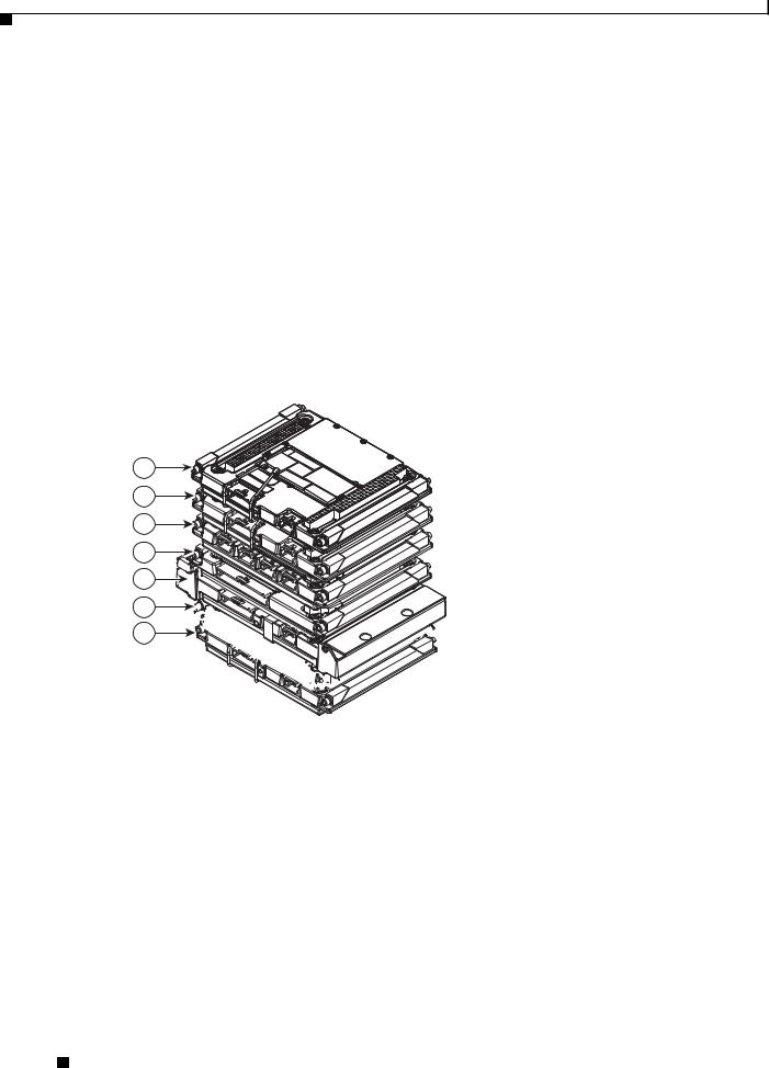
Figure 1-1 shows an exploded view of a Cisco 3230 Rugged Enclosure. (The design of the longer Cisco 3270 Rugged Enclosure is similar.)
Figure 1-1 Exploded View of a Rugged Enclosure
4
3
270439
1 |
2 |
5 |
1 |
I/O end cap1 |
2 |
Wiring card |
3 |
Card stack |
4 |
Extrusion (body of the enclosure) |
|
|
|
|
5 |
Antenna end cap |
|
|
|
|
|
|
1. This end cap shows four serial ports, but the typical configuration has two serial ports.
The enclosures are sealed by using O-rings between the extrusion and the end caps.
Cisco 3200 Series Router Hardware Reference
1-2 |
OL-5816-10 |
|
|

Chapter 1 Cisco 3200 Rugged Enclosures
Cisco 3270 Rugged Enclosure
The Cisco 3270 Rugged Enclosure operates in a temperature range from –40 to +165°F (–40 to +74°C) when all ports are copper. If the Cisco 3270 Router includes a fiber-optic port, it operates at a temperature range from –40 to +147°F (–40 to +64°C).
The Cisco 3270 Rugged Enclosure is designed to meet NEMA4 requirements. Figure 1-2 shows an example of a fully assembled Cisco 3270 Rugged Enclosure. Note the greater length to accommodate the Cisco 3270 Rugged Router card and future expansion.
Figure 1-2 Cisco 3270 Rugged Enclosure
270440
Cisco 3200 Series Router Hardware Reference
|
OL-5816-10 |
1-3 |
|
|
|

Chapter 1 Cisco 3200 Rugged Enclosures
Cisco 3270 Router Card Stack
The Cisco 3270 Rugged Enclosure supports the following configurations:
•One Cisco 3270 Rugged Router card
•Up to three Wireless Mobile Interface Cards (WMICs)
•One Serial Mobile Interface Card (SMIC)
•One Fast Ethernet Switch Mobile Interface Card (FESMIC)
•One Cisco Mobile Router Power Card (MRPC)
A base configuration includes one of each of the following: Cisco 3270 Rugged Router card, SMIC, FESMIC, and MRPC.
In the Cisco 3270 Rugged Enclosure, the cards should be stacked in the order shown in Figure 1-3. The figure includes three optional WMICs. If WMICs are added, the first WMIC should be installed on the bottom of the stack, and the next two WMICs should be installed at the top of the stack.
Figure 1-3 Example of a Cisco 3270 Router Card Stack with Three Optional WMICs
8
7
6
5
4
3
2
9
1
270441
1 |
WMIC 1 |
2 |
MRPC |
|
|
|
|
3 |
MARC |
4 |
SMIC |
|
|
|
|
5 |
FESMIC |
6 |
WMIC 2 |
|
|
|
|
7 |
WMIC 3 |
8 |
Small-form-factor pluggable |
|
|
|
(SFP) module |
|
|
|
|
9 |
Second PCI bus |
|
|
|
|
|
|
Cisco 3200 Series Router Hardware Reference
1-4 |
OL-5816-10 |
|
|

Chapter 1 Cisco 3200 Rugged Enclosures
Cisco 3230 Rugged Enclosure
The Cisco 3230 Rugged Enclosure is designed to accommodate the Mobile Access Router Card (MARC). This enclosure operates in a temperature range from –40 to 165°F (–40 to +74°C), and is certified to meet NEMA4 requirements. Figure 1-4 shows an example of a Cisco 3230 Rugged Enclosure.
Figure 1-4 Cisco 3230 Rugged Enclosure
1
270442
2
1 |
Front of the enclosure (I/O end cap)1 |
2 |
Back of the enclosure (antenna end cap) |
1. This end cap shows four serial ports, but the typical configuration has two serial ports.
Cisco 3200 Series Router Hardware Reference
|
OL-5816-10 |
1-5 |
|
|
|
Chapter 1 Cisco 3200 Rugged Enclosures
Cisco 3230 Router Card Stack
The Cisco 3230 Rugged Enclosure can accommodate up to seven cards, including:
•One MARC
•Up to three WMICs
•One SMIC (or no SMIC)
•One FESMIC
•One MRPC
A basic configuration includes one of each of the following: MARC, SMIC, FESMIC, WMIC, and MRPC.
In the Cisco 3230 Rugged Enclosure, the cards should be stacked in the order shown in Figure 1-5. The two optional WMICs are on the top of the stack.
Figure 1-5 Cisco 3230 Router Stack
7
6
5
4
3
2
1
 270443
1 |
WMIC 1 |
2 |
MRPC |
|
|
|
|
3 |
MARC |
4 |
SMIC |
|
|
|
|
5 |
FESMIC |
6 |
WMIC 2 |
|
|
|
|
7 |
WMIC 3 |
|
|
|
|
|
|
Cisco 3200 Series Router Hardware Reference
1-6 |
OL-5816-10 |
|
|
Chapter 1 Cisco 3200 Rugged Enclosures
Rugged Enclosure End Caps
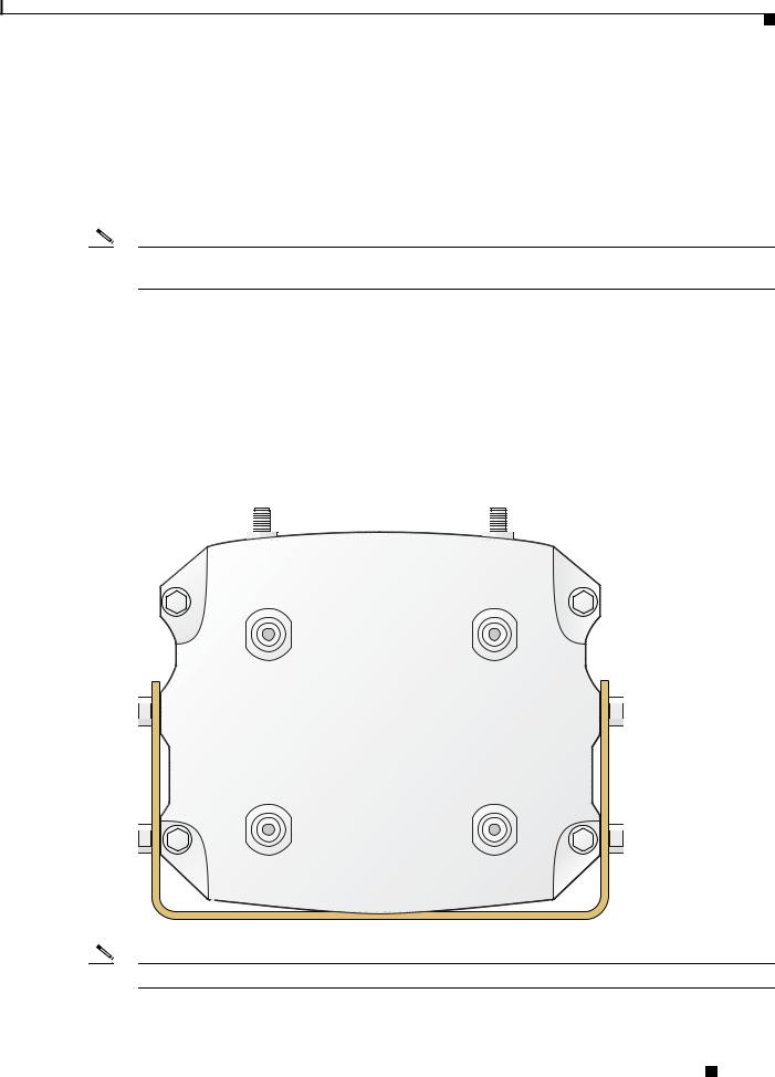
Each Cisco 3200 Rugged Enclosure has two end caps: an antenna end cap that connects to the back of the enclosure, and an I/O end cap that connects to the front of the enclosure. The port configurations of the I/O end caps vary, based on the contents of the enclosure. For example, the number and location of antenna ports installed on the antenna end cap depend on how many WMICs are installed in the enclosure.
Note To prevent exposure to the elements, we recommend using the protective port covers (provided) on ports that are not in use and using port covers (provided) on the mating cables.
Antenna End Cap
The antenna end cap has four antenna ports on the flat side and two ports on the top surface. The end cap is used with the Cisco 3270 Rugged Enclosure or the Cisco 3230 Rugged Enclosure. The antenna ports are connector type RP-TNC. Each RP-TNC is connected internally to a WMIC. Typically, two antenna ports are used to support each WMIC. If fewer than three WMICs are installed, the unused antenna connector ports are sealed with a cap to protect them from the environment.
Figure 1-6 Cisco 3200 Rugged Enclosure Antenna End Cap with a Mounting Bracket
135533
Note By default, the Cisco 3205 WMIC uses the right antenna to receive and transmit data.
Cisco 3200 Series Router Hardware Reference
|
OL-5816-10 |
1-7 |
|
|
|

Chapter 1 Cisco 3200 Rugged Enclosures
Note For additional information on antennas and antenna cables, see the “Antenna Basics” technical note at http://www.cisco.com/en/US/products/hw/wireless/ps458/products_installation_guide_chapter09186a0 08007f74a.html
and the “Antenna Cabling” technical note at http://www.cisco.com/en/US/tech/tk722/tk809/technologies_tech_note09186a00801c12c2.shtml
I/O End Caps for the Cisco 3200 Rugged Enclosures
The I/O end cap has multiple connectors for connecting power and data cables. The end cap configurations shown in this section are fully populated; however, the number of ports and their functions may differ, depending upon the number of WMICs in the system.
End Cap Fast Ethernet and WMIC Console Ports
Internally, five Fast Ethernet ports are available: one routed Fast Ethernet port on the router card and four switched Fast Ethernet ports on the Fast Ethernet Switch Mobile Interface Card (FESMIC). When a WMIC is installed in addition to the router, the WMIC Fast Ethernet port is connected internally to the routed Fast Ethernet port on the router card or is connected to one of the switched Fast Ethernet ports on the FESMIC to provide a communications link with the router. In contrast, the Serial Mobile Interface Card (SMIC) and FESMIC communicate with the router through the bus. All the router Fast Ethernet ports are addressed by using the slot/port format.
In typical configurations, the first WMIC Fast Ethernet port is connected to the routed Fast Ethernet port on the router card. The Fast Ethernet ports of the second and third WMICs are connected to FESMIC switched Fast Ethernet ports. The differences in the types of the router Fast Ethernet ports that the WMICs are connected to affect how they are configured, as, for example, when uploading a Cisco IOS image to a WMIC.
The WMIC runs an independent Cisco IOS image and when you configure the WMIC, the link forms an internal LAN. In standard configurations, the WMIC Fast Ethernet port is never brought out to the end cap.
The WMIC console port is brought out to the corresponding RJ-45 port on the I/O end cap, replacing a Fast Ethernet port. If the router includes one WMIC, the EIA/TIA-232 WMIC console port replaces a Fast Ethernet port on the end cap. If the router includes two WMICs, two WMIC EIA/TIA-232 console ports replace two Fast Ethernet ports on the end cap.
Note At present, even if the router contains no WMICs, in standard configurations the maximum three Fast Ethernet ports are brought out to the end cap. Unused EIA/TIA-232 ports are sealed.
Cisco 3200 Series Router Hardware Reference
1-8 |
OL-5816-10 |
|
|
Chapter 1 Cisco 3200 Rugged Enclosures
Cisco 3270 Router I/O End Cap
Figure 1-7 shows the Cisco 3270 Router I/O end cap.
Figure 1-7 Cisco 3270 Router End Cap
1 |
2 |
3 |
4 |
5 |
6 |
|
7 |
15
14
13
12
11
10
9
8
270447
1 |
Router console port |
2 |
FE0 port |
|
|
|
|
3 |
FE1 port |
4 |
FE0X port |
|
|
|
|
5 |
GE0 (Gigabit Ethernet) port |
6 |
Fiber-Optic port (shown) or Copper Gigabit |
|
|
|
Ethernet (GE1) port |
|
|
|
|
7 |
USB0 (bottom) and USB1 (top) ports |
8 |
Ser2 Smart Serial port |
|
|
|
|
9 |
Power input |
10 |
Ser1 EIA/TIA-232 (DCE) port |
|
|
|
|
11 |
AUX port |
12 |
Ser0 EIA/TIA-232 (DCE) port |
|
|
|
|
13 |
FE1X port or WMIC 3 console port1 |
14 |
FE2X port or WMIC 2 console port1 |
15 |
FE3X port or WMIC 1 console port1 |
|
|
1. The configuration of the port is set at the factory and labeled accordingly.
The RJ-45 connectors identified as 8, 9, and 10 are Fast Ethernet ports or WMIC console ports, depending on the configuration of the system. For example, if two WMICs have been added to the router, RJ-45 ports 8 and 9 are labeled WMIC 1 and WMIC 2. Port 10 is labeled FE1X.
Cisco 3200 Series Router Hardware Reference
|
OL-5816-10 |
1-9 |
|
|
|

Chapter 1 Cisco 3200 Rugged Enclosures
Note The connectors are sealed at the factory with captive dust covers (not shown) that seal the ports and protect the pins. The dust covers should be used to seal the ports when the ports are not covered by cable connectors.
Fiber Optic Connector IP–67 Integrity
When the fiber-optic port is not connected or otherwise in use, the protective cover should be used to seal the port. To seal the fiber-optic port when it is connected to a cable, use connectors that maintain IP-67 integrity. The part numbers for the connectors are Tyco 1828618–1 and Tyco 1828618–2.
Caution When connecting fiber-optic cables, observe all standard procedures for safety, and maintain a clean connection.
Power Connector IP-67 Integrity
To seal the Tyco DC Power input power connector and maintain IP-67 integrity, use the following parts:
•796094-2–CPC housing
•66101-3–contact
•207489-1–boot
•207490-1–cable (grip size 11)
Smart Serial Port External Seal for System Integrity
When the Smart Serial port is not connected or otherwise in use, the protective cover should be used to seal the port. To seal the Smart Serial port when the port is connected to a cable, complete the steps in Appendix A, “Smart Serial Port External Seal.” in the Cisco 3200 Series Router Hardware Reference.
Cisco 3200 Series Router Hardware Reference
1-10 |
OL-5816-10 |
|
|

Chapter 1 Cisco 3200 Rugged Enclosures
USB Flash Storage Device Caveat
In some cases, using two USB flash storage devices causes unpredictable results (CSCsd11136).
If one USB flash storage device is plugged into a USB port and a second USB flash storage device is plugged into or unplugged from the other port, an error might occur (CSCsd44152). The error message is, “USB_HOST_STACK-6-USB_FLASH_READY_TEST_TIME: USB flash 'Ready' test time over
4 seconds.”
If an unsupported USB flash storage device is plugged into a USB port, an error might occur (CSCsd44152). The error message is, “Failed to enumerate a USB device as not able to read the device's description.”
To correct the problems, remove any unsupported USB flash storage device and use only one supported device in one of the two USB ports. The Cisco-supported flash storage devices listed below.
Item# |
Vendor |
Part Number |
|
|
|
16-3153-01 |
SANDISK |
SDUJGU0-256-926 |
|
|
|
16-3153-01 |
M-SYSTEMS |
8U-52E-0256-12A01C |
|
|
|
16-3152-01 |
SANDISK |
SDUJGU0-128-926 |
|
|
|
16-3152-01 |
M-SYSTEMS |
8U-52E-0128-12A01C |
|
|
|
16-3151-01 |
SANDISK |
SDUJGU0-64-926 |
|
|
|
16-3151-01 |
M-SYSTEMS |
8U-52E-0064-12A01C |
|
|
|
Cisco 3200 Series Router Hardware Reference
|
OL-5816-10 |
1-11 |
|
|
|

Chapter 1 Cisco 3200 Rugged Enclosures
Cisco 3230 Router I/O End Cap
Figure 1-8 shows the Cisco 3230 Router I/O end cap. It has multiple connectors that can be used to connect power and data cables.
Figure 1-8 Cisco 3230 Router End Cap
4 1 5 2 6 3
7
8 
|
|
|
|
270444 |
|
9 |
10 |
11 |
|
1 |
WMIC 1 console port |
|
2 |
WMIC 2 console port |
3 |
WMIC 3 console port |
|
4 |
FE0 port |
5 |
FE1X port |
|
6 |
FE2X or MARC FE0X port (for more |
|
|
|
|
information, see the “Fast Ethernet Port |
|
|
|
|
Cabling for the Cisco 3250 and Cisco 3230 |
|
|
|
|
Routers” section on page 1-16.) |
7 |
AUX port |
|
8 |
Router console port |
9 |
Ser0 RS-232 (DCE) port |
|
10 |
Ser1 RS-232 (DCE) port |
11 |
Power input |
|
|
|
Note The connectors are sealed at the factory with captive dust covers (not shown) that seal the ports and protect the pins. The dust covers should be used to seal the ports when the ports are not otherwise covered by cable connectors.
Cisco 3200 Series Router Hardware Reference
1-12 |
OL-5816-10 |
|
|
Chapter 1 Cisco 3200 Rugged Enclosures
Protective End Cap Cover
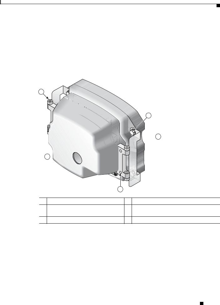
A protective end cap cover (Figure 1-9) provides weatherproof protection for the ports on the end caps of the Cisco 3200 Rugged Enclosure when the enclosure is installed outdoors. The protective end cap cover also provides added protection for in-vehicle use, inhibiting corrosion on the ports and potential damage from objects that are stored near the enclosure inside a vehicle.
The protective end cap cover has a ruggedized design for high reliability and NEMA4 compliance.
Figure 1-9 Cisco 3200 Rugged Enclosure Protective End Cap Cover
1
5
 4
4
2 
|
|
3 |
158086 |
|
|
|
|
1 |
Hinge point |
2 |
NEC cable pass-through |
3 |
Holes for 8–32 protective end cap cover |
4 |
Hinge/mounting bracket |
|
screws |
|
|
5 |
Mounting bolt |
|
|
Cisco 3200 Series Router Hardware Reference
|
OL-5816-10 |
1-13 |
|
|
|
Chapter 1 Cisco 3200 Rugged Enclosures
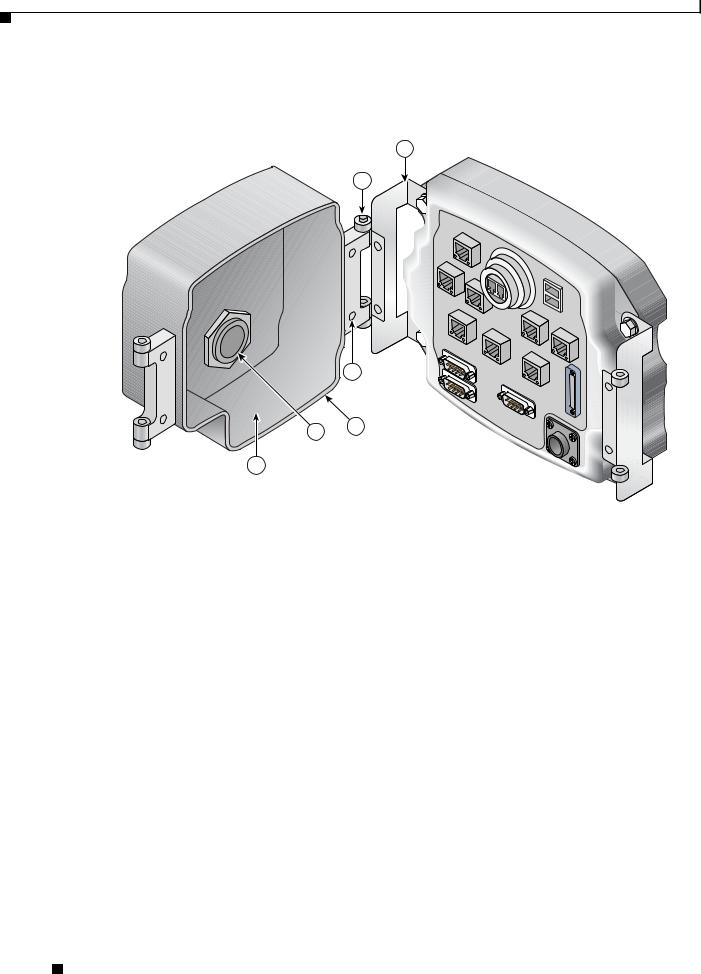
To attach the protective end cap cover to the enclosure, follow these steps (see Figure 1-10).
Figure 1-10 Protective End Cap Cover Installation
1
2
|
6 |
4 |
5 |
|
|
3 |
|
|
|
|
|
170106 |
|
|
|
|
|
|
1 |
Hinge bracket |
2 |
Hinge point |
|
|
|
|
|
|
3 |
Cable/service loop cavity |
4 |
NEC pass-through |
|
|
|
|
|
|
5 |
Gasket |
6 |
Cap mounting |
|
|
|
|
|
|
|
|
|
|
Step 1 |
Loosen the end cap mounting hardware (four 1/4-20 bolts), but do not remove the bolts. |
|||
Step 2 |
Slide the hinge brackets onto the right side and the left side of the end cap cover. The mounting tabs |
|||
|
should slide under the loosened bolts. |
|
|
|
Step 3 |
Re-torque the two loosened bolts on the right side of the end cap cover to between 58 and 68 in-lb. |
|||
Step 4 |
Ensure that the gasket is fully seated in the protective end cap cover. |
|||
Step 5 |
Close the cover on the protective end cap cover and ensure that it is fully seated. |
|||
Step 6 |
Re-torque the end cap cover bolts on left side of the end cap cover to between 58 and 68 in-lb. |
|||
Step 7 |
Tighten the 8-32 protective cover screws (18 in-lb) until they are seated. |
|||
|
|
|
|
|
For sealing, we recommend Liquid Tight Connector, which is described at the following URL: http://www.newark.com/NewarkWebCommerce/newark/en_US/mfr/brands.jsp?mfg=HUBB
Cisco 3200 Series Router Hardware Reference
1-14 |
OL-5816-10 |
|
|

Chapter 1 Cisco 3200 Rugged Enclosures
I/O End Cap Port Signals
This section describes the ports and port signals on the Cisco 3200 Rugged Enclosure I/O end caps.
Gigabit Ethernet Signal Limitations
Due to CPU and memory bus limitations, a Gigabit Ethernet port transmits and receives packets below the line rate. The line rate is lower for small frames and higher for large frames.
Small packet streams on Gigabit Ethernet ports, such as 64-byte packet streams, support up to 24 percent of full duplex, bidirectional line rate traffic without experiencing packet drops.
The 512-byte packet streams support up to 78 percent of full duplex, bidirectional line rate traffic. The 1518-byte packet streams support up to 88 percent of full duplex bidirectional line rate traffic.
At higher frame rates the RDRP receive drop counter (displayed by using the show controller g0/0 command) increases indicating dropped packets.
At higher frame rates for packet sizes greater than 512 bytes, the transmit underruns1 counter (displayed by using the show int g0/0 or show int g0/1 command) increases. The transmit underruns might cause CRC errors on the peer router.
Fast Ethernet Signals
A Cisco router identifies a Ethernet port interfaces by slot number and port number in the format of slot/port. For example, the slot/port address of a Fast Ethernet interface on the Cisco 3230 Rugged Enclosure is 0/0.
The Cisco 3270 Router Ethernet port signals are in compliance with IEEE 802.3. The interfaces support the following:
•Autonegotiation and parallel detection MII interface with extended register capability for 10/100BASE-TX or 10/100/1000BASE-TX connections.
•Full-duplex and half-duplex modes.
•3.3V operation low power consumption (300 mW typical).
•Low-power sleep mode.
•Robust baseline wander correction performance.
•MDIX support (Fast Ethernet and Gigabit Ethernet copper only).
•Jumbo Frame (4400 bytes) support on Gigabit Ethernet interfaces.
•10BASE-T or 100BASE-TX using a single Ethernet connection.
•10BASE-T, 100BASE-TX, or 1000BASE-TX using a Gigabit Ethernet copper connection.
•100BAFX/100LX, 1000BASE-SX, 1000BASE-LX/LH for Gigabit Ethernet fiber-optic connections. (The speed is not configurable.)
•Standard carrier signal multiple access collision detect (CSMA/CD) or full-duplex operation.
•Integrated programmable LED drivers.
1.Transmit underrun–an error on interfaces when the data is not ready on the memory bus when the system attempts to transmit the data; a bad packet is transmitted.
Cisco 3200 Series Router Hardware Reference
|
OL-5816-10 |
1-15 |
|
|
|

Chapter 1 Cisco 3200 Rugged Enclosures
The Cisco 3230 Router Ethernet port signals are in compliance with IEEE 802.3. The interfaces support the following:
•Autonegotiation and parallel detection MII interface with extended register capability for 10/100BASE-TX connections
•Full-duplex and half-duplex modes
•3.3V operation low power consumption (300 mW typical)
•Low-power sleep mode
•10BASE-T or 100BASE-TX using a single Ethernet connection
•Robust baseline wander correction performance
•Standard carrier signal multiple access collision detect (CSMA/CD) or full-duplex operation
•Integrated programmable LED drivers
Fast Ethernet Port Cabling for the Cisco 3250 and Cisco 3230 Routers
Most Cisco 3200 Series router Ethernet ports support autodetection. If the device that the router is connected to also supports autodetection, the choice of a straight-through or crossover Ethernet cable does not matter. However, the Cisco 3250 router MARC FE0X port does not support autodetection.
To connect a port marked MARC FE0X to a routing Ethernet port that does not support autodetection, use a straight-through Ethernet cable. To connect a MARC FE0X port to a hub, switch, a router hub, or switch port, use a crossover Ethernet cable. Table 1-1 shows the connections.
Table 1-1 |
General Guidelines for MAR Fast Ethernet Port Cabling |
||
|
|
|
|
|
|
Server, Workstation, or Personal |
Hub, Switch, Uplink Router |
Ports |
|
Computer Ethernet Link |
Ethernet Hub, or Switch |
|
|
|
|
Ports marked FE0X, FE1X, |
Straight-through cable |
Crossover cable |
|
and so forth |
|
|
|
|
|
|
|
Ports marked FE0, FE1, and |
Crossover cable |
Straight-through cable |
|
so forth |
|
|
|
|
|
|
|
For example, a port marked FE0X requires a crossover Ethernet cable to establish the Ethernet link between a Cisco 3250 router and a hub. A port that does not support autodetection marked FE0 requires a straight-through Ethernet cable to establish the Ethernet link between a Cisco 3250 router and a hub.
For additional information on cable pin assignments, see the “Cable Pinouts” chapter of the Cisco Content Services Switch Getting Started Guide at:
http://www.cisco.com/en/US/products/hw/contnetw/ps789/products_installation_guide_chapter09186a 00805f718d.html
Cisco 3200 Series Router Hardware Reference
1-16 |
OL-5816-10 |
|
|

Chapter 1 Cisco 3200 Rugged Enclosures
Console Port Signals
You can connect to the router or to a Wireless Mobile Interface Card (WMIC) by using a console cable to connect to the console interfaces.
The console port signals:
•Are asynchronous serial DCE
•Support 9.6-kbps, 19.2-kbps, 38.4-kbps, 57.6-kbps, and 115.2-kbps baud rates
•Support full modem control of DTR, DSR, RTS, and CTS signals
AUX Port Signals
The AUX port is a serial asynchronous port that supports the following speeds:
•Cisco 3270 Rugged Router card in the Cisco 3270 Router: 1.2 kbps, 2.4 kbps, 4.8 kbps, 9.6 kbps,
19.2kbps, 38.4 kbps, 57.6 kbps, 115.2 kbps, and 460 kbps.
•Mobile Access Router Card (MARC) in the Cisco 3230 Router: 1.2 kbps, 2.4 kbps, 4.8 kbps,
9.6kbps, 19.2 kbps, 38.4 kbps, 57.6 kbps, and 115.2 kbps.
The AUX port supports the following:
•Asynchronous serial DTE
•5 to 8 data bits
•1, 1.5, or 2 stop bits
•Odd, even, or no parity
•Flow control by using RTS, CTS, DTR, and CDC signals
Cisco 3200 Series Router Hardware Reference
|
OL-5816-10 |
1-17 |
|
|
|

Chapter 1 Cisco 3200 Rugged Enclosures
Cisco 3200 Rugged Enclosure LED Indications
This section describes the LED indications for the Cisco 3200 Rugged Enclosure I/O end caps.
Note The behavior of the WMIC LEDs is described in the “WMIC Console LEDs” section on page 1-19.
Cisco 3270 Rugged Enclosure I/O End Cap LED Indications
Table 1-2 lists the LEDs for the Cisco 3270 Rugged Enclosure I/O end caps and their indications.
Table 1-2 LEDs for the Cisco 3270 Rugged Enclosure End Cap
LED |
Indication |
|
|
Cisco 3270 Rugged Router card |
Solid green: OK. |
|
Blinking: Booting and self-testing. |
|
Black: Not OK or the power is off. |
|
|
Serial Status/Link (1 status/link |
Solid green: Link OK. |
LED per serial port) |
Black: No link is detected. |
|
Amber blink: Activity. |
|
|
Fast Ethernet |
Link LED |
(1 LED per port, except for the |
Solid green: Link OK. |
fiber-optic port, which has no |
Black: No link is detected. |
LEDs) |
Activity LED |
|
|
|
Black: No activity and no connection. |
|
Green blink: Activity. |
|
|
Gigabit Ethernet |
Link LED |
(2 LEDs per port) |
Solid green: Link OK. |
|
Black: no link is detected. |
|
Activity LED |
|
Solid green: Link OK. |
|
Black: No activity. |
|
Green blink: Activity. |
|
|
Console |
Solid green: Link OK. |
|
Black: No activity. |
|
Green blink: Activity. |
|
|
WMIC Console (Installation or |
For installation mode, see Table 1-4 on page 1-19. |
Operation Mode) |
For operation mode, see Table 1-5 on page 1-20. |
|
|
|
|
Cisco 3200 Series Router Hardware Reference
1-18 |
OL-5816-10 |
|
|
Loading...