


 Loading...
Cisco Aironet 1300 Series Outdoor
Access Point/Bridge Hardware Installation
Guide
April 2005
Corporate Headquarters
Cisco Systems, Inc. 170 West Tasman Drive
San Jose, CA 95134-1706 USA http://www.cisco.com Tel: 408 526-4000
800 553-NETS (6387) Fax: 408 526-4100
Text Part Number: OL-5048-02
THE SPECIFICATIONS AND INFORMATION REGARDING THE PRODUCTS IN THIS MANUAL ARE SUBJECT TO CHANGE WITHOUT NOTICE. ALL STATEMENTS, INFORMATION, AND RECOMMENDATIONS IN THIS MANUAL ARE BELIEVED TO BE ACCURATE BUT ARE PRESENTED WITHOUT WARRANTY OF ANY KIND, EXPRESS OR IMPLIED. USERS MUST TAKE FULL RESPONSIBILITY FOR THEIR APPLICATION OF ANY PRODUCTS.
THE SOFTWARE LICENSE AND LIMITED WARRANTY FOR THE ACCOMPANYING PRODUCT ARE SET FORTH IN THE INFORMATION PACKET THAT SHIPPED WITH THE PRODUCT AND ARE INCORPORATED HEREIN BY THIS REFERENCE. IF YOU ARE UNABLE TO LOCATE THE SOFTWARE LICENSE OR LIMITED WARRANTY, CONTACT YOUR CISCO REPRESENTATIVE FOR A COPY.
The following information is for FCC compliance of Class A devices: This equipment has been tested and found to comply with the limits for a Class A digital device, pursuant to part 15 of the FCC rules. These limits are designed to provide reasonable protection against harmful interference when the equipment is operated in a commercial environment. This equipment generates, uses, and can radiate radio-frequency energy and, if not installed and used in accordance with the instruction manual, may cause harmful interference to radio communications. Operation of this equipment in a residential area is likely to cause harmful interference, in which case users will be required to correct the interference at their own expense.
The following information is for FCC compliance of Class B devices: The equipment described in this manual generates and may radiate radio-frequency energy. If it is not installed in accordance with Cisco’s installation instructions, it may cause interference with radio and television reception. This equipment has been tested and found to comply with the limits for a Class B digital device in accordance with the specifications in part 15 of the FCC rules. These specifications are designed to provide reasonable protection against such interference in a residential installation. However, there is no guarantee that interference will not occur in a particular installation.
Modifying the equipment without Cisco’s written authorization may result in the equipment no longer complying with FCC requirements for Class A or Class B digital devices. In that event, your right to use the equipment may be limited by FCC regulations, and you may be required to correct any interference to radio or television communications at your own expense.
You can determine whether your equipment is causing interference by turning it off. If the interference stops, it was probably caused by the Cisco equipment or one of its peripheral devices. If the equipment causes interference to radio or television reception, try to correct the interference by using one or more of the following measures:
•Turn the television or radio antenna until the interference stops.
•Move the equipment to one side or the other of the television or radio.
•Move the equipment farther away from the television or radio.
•Plug the equipment into an outlet that is on a different circuit from the television or radio. (That is, make certain the equipment and the television or radio are on circuits controlled by different circuit breakers or fuses.)
Modifications to this product not authorized by Cisco Systems, Inc. could void the FCC approval and negate your authority to operate the product.
The Cisco implementation of TCP header compression is an adaptation of a program developed by the University of California, Berkeley (UCB) as part of UCB’s public domain version of the UNIX operating system. All rights reserved. Copyright © 1981, Regents of the University of California.
NOTWITHSTANDING ANY OTHER WARRANTY HEREIN, ALL DOCUMENT FILES AND SOFTWARE OF THESE SUPPLIERS ARE PROVIDED “AS IS” WITH ALL FAULTS. CISCO AND THE ABOVE-NAMED SUPPLIERS DISCLAIM ALL WARRANTIES, EXPRESSED OR IMPLIED, INCLUDING, WITHOUT LIMITATION, THOSE OF MERCHANTABILITY, FITNESS FOR A PARTICULAR PURPOSE AND NONINFRINGEMENT OR ARISING FROM A COURSE OF DEALING, USAGE, OR TRADE PRACTICE.
IN NO EVENT SHALL CISCO OR ITS SUPPLIERS BE LIABLE FOR ANY INDIRECT, SPECIAL, CONSEQUENTIAL, OR INCIDENTAL DAMAGES, INCLUDING, WITHOUT LIMITATION, LOST PROFITS OR LOSS OR DAMAGE TO DATA ARISING OUT OF THE USE OR INABILITY TO USE THIS MANUAL, EVEN IF CISCO OR ITS SUPPLIERS HAVE BEEN ADVISED OF THE POSSIBILITY OF SUCH DAMAGES.
CCSP, CCVP, the Cisco Square Bridge logo, Follow Me Browsing, and StackWise are trademarks of Cisco Systems, Inc.; Changing the Way We Work, Live, Play, and Learn, and iQuick Study are service marks of Cisco Systems, Inc.; and Access Registrar, Aironet, ASIST, BPX, Catalyst, CCDA, CCDP, CCIE, CCIP, CCNA, CCNP, Cisco, the Cisco Certified Internetwork Expert logo, Cisco IOS, Cisco Press, Cisco Systems, Cisco Systems Capital, the Cisco Systems logo, Cisco Unity, Empowering the Internet Generation, Enterprise/Solver, EtherChannel, EtherFast, EtherSwitch, Fast Step, FormShare, GigaDrive, GigaStack, HomeLink, Internet Quotient, IOS, IP/TV, iQ Expertise, the iQ logo, iQ Net Readiness Scorecard, LightStream, Linksys, MeetingPlace, MGX, the Networkers logo, Networking Academy, Network Registrar, Packet, PIX, Post-Routing, Pre-Routing, ProConnect, RateMUX, ScriptShare, SlideCast, SMARTnet, StrataView Plus, TeleRouter, The Fastest Way to Increase Your Internet Quotient, and TransPath are registered trademarks of Cisco Systems, Inc. and/or its affiliates in the United States and certain other countries.
All other trademarks mentioned in this document or Website are the property of their respective owners. The use of the word partner does not imply a partnership relationship between Cisco and any other company. (0502R)
Cisco Aironet 1300 Series Outdoor Access Point/Bridge Hardware Installation Guide
© 2005 Cisco Systems, Inc. All rights reserved.

C O N T E N T S
|
|
Preface |
ix |
|
|
|
|
|
|
|
|
|
|
|
|
|
Objectives |
ix |
|
|
|
|
|
|
|
|
|
|
|
|
|
Audience |
ix |
|
|
|
|
|
|
|
|
|
|
|
|
|
Organization |
ix |
|
|
|
|
|
|
|
|
|
||
|
|
Conventions |
|
x |
|
|
|
|
|
|
|
|
|
|
|
|
Related Publications |
xii |
|
|
|
|
|
|
|
|
|||
|
|
Obtaining Documentation |
xii |
|
|
|
|
|
|
|
||||
|
|
Cisco.com |
xii |
|
|
|
|
|
|
|
|
|
||
|
|
Documentation DVD |
xiii |
|
|
|
|
|
|
|
||||
|
|
Ordering Documentation xiii |
|
|
|
|
|
|
||||||
|
|
Documentation Feedback |
xiii |
|
|
|
|
|
|
|
||||
|
|
Cisco Product Security Overview |
xiv |
|
|
|
|
|
|
|||||
|
|
Reporting Security Problems in Cisco Products |
xiv |
|||||||||||
|
|
Obtaining Technical Assistance |
xiv |
|
|
|
|
|
|
|||||
|
|
Cisco Technical Support Website |
xv |
|
|
|
|
|
||||||
|
|
Locating the Product Serial Number |
xv |
|
|
|
|
|
||||||
|
|
Submitting a Service Request |
xvi |
|
|
|
|
|
|
|||||
|
|
Definitions of Service Request Severity |
xvii |
|
|
|
|
|||||||
|
|
Obtaining Additional Publications and Information |
xvii |
|||||||||||
|
Overview |
|
|
|
|
|
|
|
|
|
|
|
|
|
C H A P T E R 1 |
1-1 |
|
|
|
|
|
|
|
|
|
|
|
||
|
|
Key Features |
1-2 |
|
|
|
|
|
|
|
|
|
||
|
|
Power |
1-3 |
|
|
|
|
|
|
|
|
|
||
|
|
Integrated Antenna |
1-3 |
|
|
|
|
|
|
|
||||
|
|
External Antenna |
1-4 |
|
|
|
|
|
|
|
||||
|
|
Ethernet Ports |
1-4 |
|
|
|
|
|
|
|
|
|||
|
|
Enclosure |
1-4 |
|
|
|
|
|
|
|
|
|
||
|
|
Connectors 1-4 |
|
|
|
|
|
|
|
|
|
|||
|
|
LEDs |
1-5 |
|
|
|
|
|
|
|
|
|
|
|
|
|
Operating Roles |
1-6 |
|
|
|
|
|
|
|
|
|||
|
|
Network Configuration Examples |
1-7 |
|
|
|
|
|
|
|||||
|
|
Point-to-Point Bridge Configuration |
1-7 |
|
|
|
|
|
||||||
|
|
Port Aggregation or Redundancy Bridge Configuration 1-7 |
||||||||||||
|
|
Point-to-Multipoint Bridge Configuration |
1-8 |
|
|
|
|
|||||||
|
|
|
|
|
Cisco Aironet 1300 Series Outdoor Access Point/Bridge Hardware Installation Guide |
|
|
|
||||||
|
|
|
|
|
|
|||||||||
|
|
|
|
|
|
|
|
|
|
|
|
|
|
|
|
OL-5048-02 |
|
|
|
|
|
|
|
|
|
|
|
iii |
|
|
|
|
|
|
|
|
|
|
|
|
|
|
||

Contents
|
|
Access Point Configuration |
1-8 |
|
|
|||
|
|
Workgroup Bridge Configuration |
1-9 |
|
||||
|
|
Installation Overview |
|
|
|
|
|
|
C H A P T E R |
2 |
|
2-1 |
|
|
|
|
|
|
|
Safety Warnings |
2-2 |
|
|
|
|
|
|
|
All Installations |
2-2 |
|
|
|
|
|
|
|
Outdoor and Vehicle Installations |
2-3 |
|
||||
|
|
Vehicle Bridge Installations |
2-3 |
|
|
|||
|
|
Safety Information |
2-3 |
|
|
|
|
|
|
|
FCC Safety Compliance Statement |
2-3 |
|
||||
|
|
Safety Precautions |
2-4 |
|
|
|
||
|
|
Typical Outdoor Installation Components 2-5 |
|
|||||
|
|
Installation Guidelines |
2-5 |
|
|
|
||
|
|
Site Surveys 2-6 |
|
|
|
|
|
|
|
|
Unpacking the Access Point/Bridge 2-6 |
|
|||||
|
|
Package Contents |
2-6 |
|
|
|
||
|
|
Before Beginning the Installation |
2-7 |
|
|
|||
|
|
Installation Summary |
2-9 |
|
|
|
||
|
|
Mounting and Alignment Overview |
|
|
||||
C H A P T E R |
3 |
3-1 |
|
|||||
|
|
Mounting the Access Point/Bridge |
3-2 |
|
||||
|
|
Mounting Hardware |
3-2 |
|
|
|
|
|
|
|
Window Mounting |
3-3 |
|
|
|
||
|
|
Multi-Function Mount |
3-3 |
|
|
|
||
|
|
Access Point/Bridge Bracket |
3-4 |
|
||||
|
|
Mast Bracket |
3-4 |
|
|
|
||
|
|
LEDs 3-5 |
|
|
|
|
|
|
|
|
Aligning the Bridge Antenna Using RSSI LED Indications |
3-7 |
|||||
|
|
Using the Web-Browser Interface |
|
|
|
|||
C H A P T E R |
4 |
4-1 |
|
|
||||
|
|
Using the Web-Browser Interface Management Pages |
4-2 |
|||||
|
|
Using Action Buttons |
4-3 |
|
|
|
||
|
|
Character Restrictions in Entry Fields 4-4 |
|
|||||
|
|
Using Online Help |
4-4 |
|
|
|
||
|
|
Connecting Locally to the Ethernet Port |
4-5 |
|
||||
Cisco Aironet 1300 Series Outdoor Access Point/Bridge Hardware Installation Guide
|
iv |
OL-5048-02 |
|
|
|

Contents
C H A P T E R |
5 |
Configuring the Access Point/Bridge for the First Time |
5-1 |
|
|
|
|||||||||
|
|
|
Before You Start 5-2 |
|
|
|
|
|
|
|
|
|
|
|
|
|
|
|
Resetting the Access Point/Bridge to Default Settings |
5-2 |
|
|
|
||||||||
|
|
|
Default IP Address Behavior |
5-2 |
|
|
|
|
|
|
|
|
|
||
|
|
|
Default SSID and Default Role |
5-3 |
|
|
|
|
|
|
|
|
|
||
|
|
|
Obtaining and Assigning an IP Address |
|
5-3 |
|
|
|
|
|
|
||||
|
|
|
Connecting to the Access Point/Bridge Locally |
5-3 |
|
|
|
|
|||||||
|
|
|
Using the Power Injector’s Ethernet Port |
5-3 |
|
|
|
|
|
||||||
|
|
|
Using the Power Injector’s Console Port |
5-4 |
|
|
|
|
|
||||||
|
|
|
Assigning Basic Settings |
5-4 |
|
|
|
|
|
|
|
|
|
|
|
|
|
|
Default Settings on the Express Setup Page |
5-8 |
|
|
|
|
|||||||
|
|
|
Enabling the Radio Interfaces |
5-9 |
|
|
|
|
|
|
|
||||
|
|
|
Adjusting Output Power Level |
5-9 |
|
|
|
|
|
|
|
|
|
||
|
|
|
Configuring Basic Security Settings |
5-9 |
|
|
|
|
|
|
|
||||
|
|
|
Understanding Express Security Settings |
5-11 |
|
|
|
|
|||||||
|
|
|
Using VLANs |
5-11 |
|
|
|
|
|
|
|
|
|
|
|
|
|
|
Express Security Types |
5-11 |
|
|
|
|
|
|
|
|
|||
|
|
|
Express Security Limitations |
5-12 |
|
|
|
|
|
|
|||||
|
|
|
Using the Express Security Page |
5-13 |
|
|
|
|
|
||||||
|
|
|
Finding the IP Address Using the CLI |
|
5-13 |
|
|
|
|
|
|
||||
|
|
|
Assigning an IP Address Using the CLI |
5-14 |
|
|
|
|
|
|
|||||
|
|
|
Using a Telnet Session to Access the CLI |
5-14 |
|
|
|
|
|
||||||
|
|
Using the Command-Line Interface |
|
|
|
|
|
|
|
|
|||||
C H A P T E R |
6 |
6-1 |
|
|
|
|
|
|
|
||||||
|
|
|
Connecting to the Console Serial Port |
6-2 |
|
|
|
|
|
|
|||||
|
|
|
Using a Telnet Session to Open the CLI |
|
6-3 |
|
|
|
|
|
|
||||
|
|
|
Using Secure Shell to Open the CLI |
6-3 |
|
|
|
|
|
|
|
||||
|
|
|
IOS Command Modes |
6-4 |
|
|
|
|
|
|
|
|
|
|
|
|
|
|
Getting Help 6-5 |
|
|
|
|
|
|
|
|
|
|
|
|
|
|
|
Abbreviating Commands |
6-5 |
|
|
|
|
|
|
|
|
|
|
|
|
|
|
Using no and default Forms of Commands |
6-5 |
|
|
|
|
|
||||||
|
|
|
Understanding CLI Messages |
6-6 |
|
|
|
|
|
|
|
|
|
||
|
|
|
Using Command History |
6-6 |
|
|
|
|
|
|
|
|
|
|
|
|
|
|
Changing the Command History Buffer Size |
6-7 |
|
|
|
|
|||||||
|
|
|
Recalling Commands |
6-7 |
|
|
|
|
|
|
|
|
|
|
|
|
|
|
Disabling the Command History Feature |
6-7 |
|
|
|
|
|
||||||
|
|
|
Using Editing Features |
6-8 |
|
|
|
|
|
|
|
|
|
|
|
|
|
|
Cisco Aironet 1300 Series Outdoor Access Point/Bridge Hardware Installation Guide |
|
|
|
|||||||||
|
|
|
|
||||||||||||
|
|
|
|
|
|
|
|
|
|
|
|
|
|
|
|
|
OL-5048-02 |
|
|
|
|
|
|
|
|
|
|
|
v |
|
|
|
|
|
|
|
|
|
|
|
|
|
|
|
|||

Contents
|
Enabling and Disabling Editing Features |
6-8 |
|
|||||
|
Editing Commands Through Keystrokes |
6-8 |
|
|||||
|
Editing Command Lines That Wrap |
6-9 |
|
|
||||
|
Searching and Filtering Output of show and more Commands |
6-10 |
||||||
|
Assigning an IP Address Using the CLI |
6-11 |
|
|
||||
|
Finding the Access Point/Bridge IP Address Using the CLI 6-11 |
|
||||||
|
Troubleshooting |
|
|
|
|
|
|
|
C H A P T E R 7 |
7-1 |
|
|
|
|
|
|
|
|
Checking the LEDs |
7-2 |
|
|
|
|
|
|
|
Normal Mode LED Indications |
7-2 |
|
|
|
|||
|
Power Injector |
7-5 |
|
|
|
|
|
|
|
Checking Power |
7-6 |
|
|
|
|
|
|
|
Checking Basic Configuration Settings |
7-6 |
|
|
||||
|
Default IP Address Behavior |
7-6 |
|
|
|
|||
|
Default SSID and Radio Behavior |
7-6 |
|
|
||||
|
Enabling the Radio Interface |
7-7 |
|
|
|
|||
|
SSID 7-7 |
|
|
|
|
|
|
|
|
Security Settings 7-8 |
|
|
|
|
|
||
|
Antenna Alignment |
7-8 |
|
|
|
|
|
|
|
Running the Carrier Busy Test |
7-8 |
|
|
|
|
||
|
Running the Ping or Link Test |
7-9 |
|
|
|
|
||
|
Resetting the Access Point/Bridge to the Default Configuration |
7-10 |
||||||
|
Using the Web-Browser Interface |
7-10 |
|
|
||||
|
Using the CLI |
7-10 |
|
|
|
|
|
|
|
|
|
|
Reloading the Access Point/Bridge Image |
7-11 |
|
|
||
|
|
|
|
Web-Browser Interface |
7-11 |
|
|
|
|
|
|
|
|
Browser HTTP Interface |
7-11 |
|
|
|
|
|
|
|
|
Browser TFTP Interface |
7-12 |
|
|
|
|
|
|
|
|
Obtaining the Access Point/Bridge Image File |
7-13 |
|
|||
|
|
|
|
Obtaining the TFTP Server Software |
7-13 |
|
|
||
|
Translated Safety Warnings |
|
|
|
|
|
|||
A P P E N D I X A |
A-1 |
|
|
|
|
||||
|
|
|
|
Statement 84—Warning Definition |
A-2 |
|
|
|
|
|
|
|
|
Statement 245B—Explosive Device Proximity Warning A-3 |
|||||
|
|
|
|
Statement 346—RF Exposure Limits A-4 |
|
|
|
||
|
|
|
|
Statement 1001—Work During Lightning Activity |
A-5 |
||||
|
|
|
|
Statement 1005—Circuit Breaker |
A-6 |
|
|
|
|
|
|
|
Cisco Aironet 1300 Series Outdoor Access Point/Bridge Hardware Installation Guide |
||||||
|
|
|
|||||||
|
|
|
|
|
|
|
|
|
|
|
vi |
|
|
|
|
|
|
OL-5048-02 |
|
|
|
|
|
|
|
|
|
||

Contents
|
|
|
Statement 1022—Disconnect Device |
A-7 |
|
|
|
|
|
|
|
|||
|
|
|
Statement 1024—Ground Conductor |
A-9 |
|
|
|
|
|
|
|
|||
|
|
|
Statement 1030—Equipment Installation |
A-10 |
|
|
|
|
|
|
||||
|
|
|
Statement 1033—SELV-IEC 60950 DC Power Supply |
A-12 |
|
|
|
|
||||||
|
|
|
Statement 1040—Product Disposal |
|
A-13 |
|
|
|
|
|
|
|
||
|
|
|
Statement 1052—Installing and Grounding the Antenna |
A-15 |
|
|
|
|
||||||
|
|
Declarations of Conformity and Regulatory Information |
|
|
|
|
|
|||||||
A P P E N D I X |
B |
B-1 |
|
|
|
|
||||||||
|
|
|
Manufacturers Federal Communication Commission Declaration of Conformity Statement B-2 |
|||||||||||
|
|
|
Department of Communications—Canada |
B-3 |
|
|
|
|
|
|
||||
|
|
|
Canadian Compliance Statement |
B-3 |
|
|
|
|
|
|
|
|||
|
|
|
European Community, Switzerland, Norway, Iceland, and Liechtenstein B-3 |
|
|
|
|
|||||||
|
|
|
Declaration of Conformity with Regard to the R&TTE Directive 1999/5/EC |
B-3 |
||||||||||
|
|
|
Declaration of Conformity for RF Exposure |
B-5 |
|
|
|
|
|
|
||||
|
|
|
Guidelines for Operating Cisco Aironet Access Points and Bridges in Japan |
B-5 |
||||||||||
|
|
|
Japanese Translation |
B-5 |
|
|
|
|
|
|
|
|
||
|
|
|
English Translation |
B-5 |
|
|
|
|
|
|
|
|
|
|
|
|
|
Administrative Rules for Cisco Aironet Access Points and Bridges in Taiwan |
B-6 |
||||||||||
|
|
|
All Access Points and Bridges |
|
B-6 |
|
|
|
|
|
|
|
||
|
|
|
Chinese Translation |
B-6 |
|
|
|
|
|
|
|
|
|
|
|
|
|
English Translation |
B-6 |
|
|
|
|
|
|
|
|
|
|
|
|
|
Declaration of Conformity Statements |
B-7 |
|
|
|
|
|
|
||||
|
|
|
Declaration of Conformity Statements for European Union Countries |
B-7 |
||||||||||
|
|
Access Point/Bridge Specifications |
|
|
|
|
|
|
|
|
|
|||
A P P E N D I X |
C |
|
C-1 |
|
|
|
|
|
|
|
||||
|
|
|
Bridge Operating Range |
C-4 |
|
|
|
|
|
|
|
|
|
|
|
|
Channels and Antenna Settings |
|
|
|
|
|
|
|
|
|
|||
A P P E N D I X |
D |
D-1 |
|
|
|
|
|
|
|
|
||||
|
|
|
Channels |
D-2 |
|
|
|
|
|
|
|
|
|
|
|
|
|
IEEE 802.11g (2.4-GHz Band) |
D-2 |
|
|
|
|
|
|
|
|||
|
|
|
Maximum Power Levels and Antenna Gains |
D-3 |
|
|
|
|
|
|
||||
|
|
|
IEEE 802.11g (2.4-GHz Band) |
D-3 |
|
|
|
|
|
|
|
|||
|
|
|
Changing the Access Point/Bridge Output Power |
D-4 |
|
|
|
|
|
|||||
|
|
Console Serial Cable Pinouts |
|
|
|
|
|
|
|
|
|
|
||
A P P E N D I X |
E |
E-1 |
|
|
|
|
|
|
|
|
|
|||
|
|
|
Overview |
E-2 |
|
|
|
|
|
|
|
|
|
|
|
|
|
Signals and Pinouts E-2 |
|
|
|
|
|
|
|
|
|
|
|
|
|
|
|
Cisco Aironet 1300 Series Outdoor Access Point/Bridge Hardware Installation Guide |
|
|
|
|||||||
|
|
|
|
|
||||||||||
|
|
|
|
|
|
|
|
|
|
|
|
|
|
|
|
OL-5048-02 |
|
|
|
|
|
|
|
|
|
|
|
vii |
|
|
|
|
|
|
|
|
|
|
|
|
|
|
||

Contents
A P P E N D I X F |
Load-Dump Protection for Transportation Vehicles F-1 |
|
Load-Dump Protection F-1 |
|
|
G L O S S A R Y |
|
|
|
I N D E X |
|
Cisco Aironet 1300 Series Outdoor Access Point/Bridge Hardware Installation Guide
|
viii |
OL-5048-02 |
|
|
|

Preface
This section describes the objectives, audience, organization, and conventions of the Cisco Aironet 1300 Series Outdoor Access Point/Bridge Hardware Installation Guide.
Objectives
This publication explains the steps for initial setup and basic configuration of the Cisco Aironet 1300 Series Outdoor Access Point/Bridge supporting 2.4-GHz operation. This publication also provides troubleshooting information and detailed specifications.
Audience
This publication is for the person installing and configuring the Cisco Aironet 1300 Series Outdoor Access Point/Bridge (called the access point/bridge) for the first time. The installer should be familiar with network structures, terms, and concepts.
Organization
This guide contains the following sections:
Chapter 1, “Overview,” describes the major components, features, and specifications of the access point/bridge.
Chapter 2, “Installation Overview,” provides warnings, safety information, and information needed before you begin the installation of your access point/bridge system.
Chapter 3, “Mounting and Alignment Overview,” provides an overview of components and features used during access point/bridge mounting and antenna alignment operations.
Chapter 4, “Using the Web-Browser Interface,” describes how to use the web-browser interface to configure the access point/bridge.
Chapter 5, “Configuring the Access Point/Bridge for the First Time,” describes how to enter basic access point/bridge configuration settings.
Chapter 6, “Using the Command-Line Interface,” describes how to use the command-line interface (CLI) to configure the access point/bridge.
Chapter 7, “Troubleshooting,” provides solutions to potential problems encountered during setup.
Cisco Aironet 1300 Series Outdoor Access Point/Bridge Hardware Installation Guide
|
OL-5048-02 |
ix |
|

Preface
Conventions
Appendix A, “Translated Safety Warnings,” lists translations of the safety warnings in this publication.
Appendix B, “Declarations of Conformity and Regulatory Information,” describes the regulatory conventions to which the access point/bridge conforms and provides guidelines for operating access point/bridges in Japan.
Appendix C, “Access Point/Bridge Specifications,” describes the channels and antenna settings supported by the regulatory organizations.
Appendix D, “Channels and Antenna Settings,” lists the access point radio channels and the maximum power levels supported by the world’s regulatory domains.
Appendix E, “Console Serial Cable Pinouts,” identifies the pinouts for the serial cable that connects to the power injector’s console serial port.
Appendix F, “Load-Dump Protection for Transportation Vehicles,” provides information on the electrical load-dump protection device and a vendor for the device.
Conventions
This publication uses the following conventions to convey instructions and information:
• Commands and keywords are in boldface type.
Note Means reader take note. Notes contain helpful suggestions or references to materials not contained in this manual.
Caution Means reader be careful. In this situation, you might do something that could result in equipment damage or loss of data.
Warning This warning symbol means danger. You are in a situation that could cause bodily injury. Before you work on any equipment, be aware of the hazards involved with electrical circuitry and be familiar with standard practices for preventing accidents. (To see translations of the warnings that appear in this publication, refer to the appendix “Translated Safety Warnings.”)
Waarschuwing Dit waarschuwingssymbool betekent gevaar. U verkeert in een situatie die lichamelijk letsel kan veroorzaken. Voordat u aan enige apparatuur gaat werken, dient u zich bewust te zijn van de bij elektrische schakelingen betrokken risico’s en dient u op de hoogte te zijn van standaard maatregelen om ongelukken te voorkomen. (Voor vertalingen van de waarschuwingen die in deze publicatie verschijnen, kunt u het aanhangsel “Translated Safety Warnings” (Vertalingen van veiligheidsvoorschriften) raadplegen.)
Varoitus Tämä varoitusmerkki merkitsee vaaraa. Olet tilanteessa, joka voi johtaa ruumiinvammaan. Ennen kuin työskentelet minkään laitteiston parissa, ota selvää sähkökytkentöihin liittyvistä vaaroista ja tavanomaisista onnettomuuksien ehkäisykeinoista. (Tässä julkaisussa esiintyvien varoitusten käännökset löydät liitteestä "Translated Safety Warnings" (käännetyt turvallisuutta koskevat varoitukset).)
Cisco Aironet 1300 Series Outdoor Access Point/Bridge Hardware Installation Guide
|
x |
OL-5048-02 |
|
|
|
Preface
Conventions
Attention Ce symbole d’avertissement indique un danger. Vous vous trouvez dans une situation pouvant entraîner des blessures. Avant d’accéder à cet équipement, soyez conscient des dangers posés par les circuits électriques et familiarisez-vous avec les procédures courantes de prévention des accidents. Pour obtenir les traductions des mises en garde figurant dans cette publication, veuillez consulter l’annexe intitulée « Translated Safety Warnings » (Traduction des avis de sécurité).
Warnung Dieses Warnsymbol bedeutet Gefahr. Sie befinden sich in einer Situation, die zu einer Körperverletzung führen könnte. Bevor Sie mit der Arbeit an irgendeinem Gerät beginnen, seien Sie sich der mit elektrischen Stromkreisen verbundenen Gefahren und der Standardpraktiken zur Vermeidung von Unfällen bewußt. (Übersetzungen der in dieser Veröffentlichung enthaltenen Warnhinweise finden Sie im Anhang mit dem Titel “Translated Safety Warnings” (Übersetzung der Warnhinweise).)
Avvertenza Questo simbolo di avvertenza indica un pericolo. Si è in una situazione che può causare infortuni. Prima di lavorare su qualsiasi apparecchiatura, occorre conoscere i pericoli relativi ai circuiti elettrici ed essere al corrente delle pratiche standard per la prevenzione di incidenti. La traduzione delle avvertenze riportate in questa pubblicazione si trova nell’appendice, “Translated Safety Warnings” (Traduzione delle avvertenze di sicurezza).
Advarsel Dette varselsymbolet betyr fare. Du befinner deg i en situasjon som kan føre til personskade. Før du utfører arbeid på utstyr, må du være oppmerksom på de faremomentene som elektriske kretser innebærer, samt gjøre deg kjent med vanlig praksis når det gjelder å unngå ulykker. (Hvis du vil se oversettelser av de advarslene som finnes i denne publikasjonen, kan du se i vedlegget "Translated Safety Warnings" [Oversatte sikkerhetsadvarsler].)
Aviso Este símbolo de aviso indica perigo. Encontra-se numa situação que lhe poderá causar danos fisicos. Antes de começar a trabalhar com qualquer equipamento, familiarize-se com os perigos relacionados com circuitos eléctricos, e com quaisquer práticas comuns que possam prevenir possíveis acidentes. (Para ver as traduções dos avisos que constam desta publicação, consulte o apêndice “Translated Safety Warnings” - “Traduções dos Avisos de Segurança”).
¡Advertencia! Este símbolo de aviso significa peligro. Existe riesgo para su integridad física. Antes de manipular cualquier equipo, considerar los riesgos que entraña la corriente eléctrica y familiarizarse con los procedimientos estándar de prevención de accidentes. (Para ver traducciones de las advertencias que aparecen en esta publicación, consultar el apéndice titulado “Translated Safety Warnings.”)
Varning! Denna varningssymbol signalerar fara. Du befinner dig i en situation som kan leda till personskada. Innan du utför arbete på någon utrustning måste du vara medveten om farorna med elkretsar och känna till vanligt förfarande för att förebygga skador. (Se förklaringar av de varningar som förekommer i denna publikation i appendix "Translated Safety Warnings" [Översatta säkerhetsvarningar].)
Cisco Aironet 1300 Series Outdoor Access Point/Bridge Hardware Installation Guide
|
OL-5048-02 |
xi |
|

Preface
Related Publications
Related Publications
For more information about access point/bridges and related products, refer to the following publications:
•Quick Start Guide: Cisco Aironet 1300 Series Outdoor Access Point/Bridge describes the access point/bridge, system components, and how to obtain documentation. This document is included in the shipping box with your access point/bridge.
•Cisco IOS Software Configuration Guide for Cisco Aironet Bridges describes the bridge’s management system and explains how to configure the bridge settings. This document is available on the Cisco CCO web site at the following URL:
http://www.cisco.com/univercd/cc/td/doc/product/wireless/index.htm
•Cisco IOS Software Configuration Guide for Cisco Aironet Access Points describes the access point’s management system and explains how to configure the access point settings. This document is available on the Cisco CCO web site at the following URL:
http://www.cisco.com/univercd/cc/td/doc/product/wireless/index.htm
•Cisco Aironet 1300 Series Outdoor Access Point/Bridge Mounting Instructions that was shipped with your access point/bridge provides detailed instructions for mounting the unit and aligning the antenna.
•Cisco IOS Command Reference for Cisco Aironet Access Points and Bridges describes the IOS commands supported by Cisco Aironet access points and bridges. This document is available on the Cisco CCO web site at the following URL:
http://www.cisco.com/univercd/cc/td/doc/product/wireless/index.htm
•Release Notes for Cisco Aironet 1300 Series Outdoor Access Point/Bridge describes features and caveats for the access point/bridge running IOS release 12.2(11)JA. This document is available on the Cisco CCO web site at the following URL:
http://www.cisco.com/univercd/cc/td/doc/product/wireless/index.htm
•Cisco Secure Access Control Server for Windows 2000/NT Servers Version 3.0 User Guide provides complete instructions for using Cisco Secure ACS, including steps for configuring Cisco Secure ACS to support access points and bridges. This document is available on the Cisco CCO web site at the following URL:
http://www.cisco.com/univercd/cc/td/doc/product/access/acs_soft/csacs4nt/csnt30/user/index.htm
Obtaining Documentation
Cisco documentation and additional literature are available on Cisco.com. Cisco also provides several ways to obtain technical assistance and other technical resources. These sections explain how to obtain technical information from Cisco Systems.
Cisco.com
You can access the most current Cisco documentation at this URL:
http://www.cisco.com/univercd/home/home.htm
Cisco Aironet 1300 Series Outdoor Access Point/Bridge Hardware Installation Guide
|
xii |
OL-5048-02 |
|
|
|

Preface
Documentation Feedback
You can access the Cisco website at this URL:
http://www.cisco.com
You can access international Cisco websites at this URL:
http://www.cisco.com/public/countries_languages.shtml
Documentation DVD
Cisco documentation and additional literature are available in a Documentation DVD package, which may have shipped with your product. The Documentation DVD is updated regularly and may be more current than printed documentation. The Documentation DVD package is available as a single unit.
Registered Cisco.com users (Cisco direct customers) can order a Cisco Documentation DVD (product number DOC-DOCDVD=) from the Ordering tool or Cisco Marketplace.
Cisco Ordering tool:
http://www.cisco.com/en/US/partner/ordering/
Cisco Marketplace:
http://www.cisco.com/go/marketplace/
Ordering Documentation
You can find instructions for ordering documentation at this URL:
http://www.cisco.com/univercd/cc/td/doc/es_inpck/pdi.htm
You can order Cisco documentation in these ways:
•Registered Cisco.com users (Cisco direct customers) can order Cisco product documentation from the Ordering tool:
http://www.cisco.com/en/US/partner/ordering/
•Nonregistered Cisco.com users can order documentation through a local account representative by calling Cisco Systems Corporate Headquarters (California, USA) at 408 526-7208 or, elsewhere in North America, by calling 1 800 553-NETS (6387).
Documentation Feedback
You can send comments about technical documentation to bug-doc@cisco.com.
You can submit comments by using the response card (if present) behind the front cover of your document or by writing to the following address:
Cisco Systems
Attn: Customer Document Ordering
170 West Tasman Drive
San Jose, CA 95134-9883
We appreciate your comments.
Cisco Aironet 1300 Series Outdoor Access Point/Bridge Hardware Installation Guide
|
OL-5048-02 |
xiii |
|

Preface
Cisco Product Security Overview
Cisco Product Security Overview
Cisco provides a free online Security Vulnerability Policy portal at this URL:
http://www.cisco.com/en/US/products/products_security_vulnerability_policy.html
From this site, you can perform these tasks:
•Report security vulnerabilities in Cisco products.
•Obtain assistance with security incidents that involve Cisco products.
•Register to receive security information from Cisco.
A current list of security advisories and notices for Cisco products is available at this URL:
http://www.cisco.com/go/psirt
If you prefer to see advisories and notices as they are updated in real time, you can access a Product Security Incident Response Team Really Simple Syndication (PSIRT RSS) feed from this URL:
http://www.cisco.com/en/US/products/products_psirt_rss_feed.html
Reporting Security Problems in Cisco Products
Cisco is committed to delivering secure products. We test our products internally before we release them, and we strive to correct all vulnerabilities quickly. If you think that you might have identified a vulnerability in a Cisco product, contact PSIRT:
•Emergencies — security-alert@cisco.com
•Nonemergencies — psirt@cisco.com
Tip We encourage you to use Pretty Good Privacy (PGP) or a compatible product to encrypt any sensitive information that you send to Cisco. PSIRT can work from encrypted information that is compatible with PGP versions 2.x through 8.x.
Never use a revoked or an expired encryption key. The correct public key to use in your correspondence with PSIRT is the one that has the most recent creation date in this public key server list:
http://pgp.mit.edu:11371/pks/lookup?search=psirt%40cisco.com&op=index&exact=on
In an emergency, you can also reach PSIRT by telephone:
•1 877 228-7302
•1 408 525-6532
Obtaining Technical Assistance
For all customers, partners, resellers, and distributors who hold valid Cisco service contracts, Cisco Technical Support provides 24-hour-a-day, award-winning technical assistance. The Cisco Technical Support Website on Cisco.com features extensive online support resources. In addition, Cisco Technical Assistance Center (TAC) engineers provide telephone support. If you do not hold a valid Cisco service contract, contact your reseller.
Cisco Aironet 1300 Series Outdoor Access Point/Bridge Hardware Installation Guide
|
xiv |
OL-5048-02 |
|
|
|

Preface
Obtaining Technical Assistance
Cisco Technical Support Website
The Cisco Technical Support Website provides online documents and tools for troubleshooting and resolving technical issues with Cisco products and technologies. The website is available 24 hours a day, 365 days a year, at this URL:
http://www.cisco.com/techsupport
Access to all tools on the Cisco Technical Support Website requires a Cisco.com user ID and password. If you have a valid service contract but do not have a user ID or password, you can register at this URL:
http://tools.cisco.com/RPF/register/register.do
Note Use the Cisco Product Identification (CPI) tool to locate your product serial number before submitting a web or phone request for service. You can access the CPI tool from the Cisco Technical Support Website by clicking the Tools & Resources link under Documentation & Tools. Choose Cisco Product Identification Tool from the Alphabetical Index drop-down list, or click the Cisco Product Identification Tool link under Alerts & RMAs. The CPI tool offers three search options: by product ID or model name; by tree view; or for certain products, by copying and pasting show command output. Search results show an illustration of your product with the serial number label location highlighted. Locate the serial number label on your product and record the information before placing a service call.
Locating the Product Serial Number
The access point/bridge serial number is located on the bottom of the cabinet (refer to Figure 1).
Figure 1 |
Location of Access Point/Bridge Serial Number Label |
R S E
I
SN: AAANNNNXXXX
117062
SN: AAANNNNXXXX
Cisco Aironet 1300 Series Outdoor Access Point/Bridge Hardware Installation Guide
|
OL-5048-02 |
xv |
|
Preface
Obtaining Technical Assistance
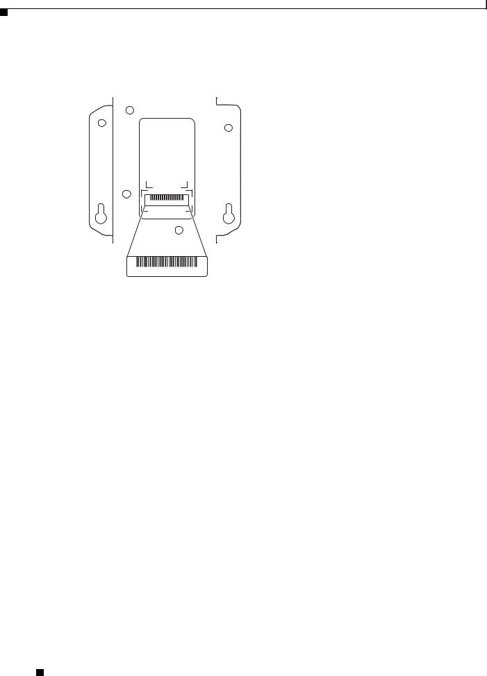
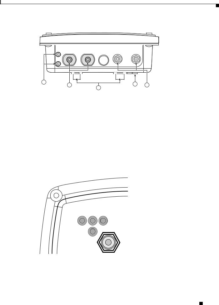
The power injector serial number is located on the bottom of the cabinet (refer to Figure 2).
Figure 2 |
|
Location of Power Injector Serial Number Label |
||
|
|
|
|
|
|
|
|
|
|
SN: AAANNNNXXXX
SN: AAANNNNXXXX
117063
The access point/bridge serial number label contains the following information:
•Model number, such as AIR-BR1300
•Serial number, such as S/N: VDF0636XXXX (11 alphanumeric digits)
•MAC address, such as MAC: 00abc65094f3 (12 hexadecimal digits)
•Location of manufacture, such as Made in Singapore
You need your product serial number when requesting support from the Cisco Technical Assistance Center.
Submitting a Service Request
Using the online TAC Service Request Tool is the fastest way to open S3 and S4 service requests. (S3 and S4 service requests are those in which your network is minimally impaired or for which you require product information.) After you describe your situation, the TAC Service Request Tool provides recommended solutions. If your issue is not resolved using the recommended resources, your service request is assigned to a Cisco TAC engineer. The TAC Service Request Tool is located at this URL:
http://www.cisco.com/techsupport/servicerequest
For S1 or S2 service requests or if you do not have Internet access, contact the Cisco TAC by telephone. (S1 or S2 service requests are those in which your production network is down or severely degraded.) Cisco TAC engineers are assigned immediately to S1 and S2 service requests to help keep your business operations running smoothly.
To open a service request by telephone, use one of the following numbers:
Asia-Pacific: +61 2 8446 7411 (Australia: 1 800 805 227)
EMEA: +32 2 704 55 55
USA: 1 800 553-2447
For a complete list of Cisco TAC contacts, go to this URL:
http://www.cisco.com/techsupport/contacts
Cisco Aironet 1300 Series Outdoor Access Point/Bridge Hardware Installation Guide
|
xvi |
OL-5048-02 |
|
|
|

Preface
Obtaining Additional Publications and Information
Definitions of Service Request Severity
To ensure that all service requests are reported in a standard format, Cisco has established severity definitions.
Severity 1 (S1)—Your network is “down,” or there is a critical impact to your business operations. You and Cisco will commit all necessary resources around the clock to resolve the situation.
Severity 2 (S2)—Operation of an existing network is severely degraded, or significant aspects of your business operation are negatively affected by inadequate performance of Cisco products. You and Cisco will commit full-time resources during normal business hours to resolve the situation.
Severity 3 (S3)—Operational performance of your network is impaired, but most business operations remain functional. You and Cisco will commit resources during normal business hours to restore service to satisfactory levels.
Severity 4 (S4)—You require information or assistance with Cisco product capabilities, installation, or configuration. There is little or no effect on your business operations.
Obtaining Additional Publications and Information
Information about Cisco products, technologies, and network solutions is available from various online and printed sources.
•Cisco Marketplace provides a variety of Cisco books, reference guides, and logo merchandise. Visit Cisco Marketplace, the company store, at this URL:
http://www.cisco.com/go/marketplace/
•Cisco Press publishes a wide range of general networking, training and certification titles. Both new and experienced users will benefit from these publications. For current Cisco Press titles and other information, go to Cisco Press at this URL:
http://www.ciscopress.com
•Packet magazine is the Cisco Systems technical user magazine for maximizing Internet and networking investments. Each quarter, Packet delivers coverage of the latest industry trends, technology breakthroughs, and Cisco products and solutions, as well as network deployment and troubleshooting tips, configuration examples, customer case studies, certification and training information, and links to scores of in-depth online resources. You can access Packet magazine at this URL:
http://www.cisco.com/packet
•iQ Magazine is the quarterly publication from Cisco Systems designed to help growing companies learn how they can use technology to increase revenue, streamline their business, and expand services. The publication identifies the challenges facing these companies and the technologies to help solve them, using real-world case studies and business strategies to help readers make sound technology investment decisions. You can access iQ Magazine at this URL:
http://www.cisco.com/go/iqmagazine
•Internet Protocol Journal is a quarterly journal published by Cisco Systems for engineering professionals involved in designing, developing, and operating public and private internets and intranets. You can access the Internet Protocol Journal at this URL:
http://www.cisco.com/ipj
Cisco Aironet 1300 Series Outdoor Access Point/Bridge Hardware Installation Guide
|
OL-5048-02 |
xvii |
|

Preface
Obtaining Additional Publications and Information
•World-class networking training is available from Cisco. You can view current offerings at this URL:
http://www.cisco.com/en/US/learning/index.html
Cisco Aironet 1300 Series Outdoor Access Point/Bridge Hardware Installation Guide
|
xviii |
OL-5048-02 |
|
|
|

C H A P T E R 1
Overview
The Cisco Aironet 1300 Series Outdoor Access Point/Bridge (hereafter called the access point/bridge) is a wireless device designed for building-to-building wireless connectivity. Operating in the 2.4-GHz band (2.400 to 2.497 GHz), using the IEEE 802.11g standard, the access point/bridge delivers 1 to 54 Mbps data rates without the need for a license. The access point/bridge is a self-contained unit designed for indoor or outdoor installations, providing differing antenna gains as well as coverage patterns. It supports point-to-point and multipoint bridging configurations.
The access point/bridge can also be configured to operate as an access point or as a workgroup bridge. When placed in access point mode, the unit supports wireless IEEE 802.11b and IEEE 802.11g client devices. When placed into workgroup bridge mode, the unit provides a wireless connection for remote wired devices to a Cisco Aironet access point or to a Cisco Aironet bridge.
The access point/bridge uses a browser-based management system, but you can also configure the access point/bridge using Cisco IOS commands or Simple Network Management Protocol (SNMP).
This chapter provides information on the following topics:
•Key Features, page 1-2
•Network Configuration Examples, page 1-7
Cisco Aironet 1300 Series Outdoor Access Point/Bridge Hardware Installation Guide
|
OL-5048-02 |
1-1 |
|
|
|

Chapter 1 Overview
Key Features
Key Features
Key features of the access point/bridge:
•Unlicensed IEEE 802.11g 2.4-GHz radio operation
•Enclosure supports indoor or outdoor installations
•Integrated antenna or external antenna configurations (see Figure 1-1)
•Dual-coax 100-Mbps Ethernet ports
•Four LEDs
•Inline power over dual-coax cables
•Console serial interface on power injector
•Receive Signal Strength Indicator (RSSI) LED patterns for easy antenna alignment
•Control using Cisco IOS commands, Internet browser, SNMP, or serial interface (on power injector)
•Three operating modes:
–Bridge mode
–Access point mode
–Workgroup bridge mode
Figure 1-1 Access Point/Bridge Configurations
1 |
2 |
117059 |
|
|
|
|
|
|
|
|
|
|
|
|
|
|
|
|
1 |
Integrated antenna access point/bridge |
2 |
External antenna access point/bridge |
||||
|
configuration |
|
configuration with external antenna |
||||
|
|
|
|
|
|
|
connectors |
|
|
|
|
|
|
|
|
Cisco Aironet 1300 Series Outdoor Access Point/Bridge Hardware Installation Guide
1-2 |
OL-5048-02 |
|
|
Chapter 1 Overview
Key Features
Note Antenna connectors are available only on the external antenna access point/bridge configuration.
Power
The access point/bridge receives inline power from the Cisco Aironet Power Injector (hereafter called the power injector). Dual-coax cables are used to provide Ethernet data and power from the power injector to the access point/bridge. The power injector is an external unit designed for operation in a sheltered environment, such as inside a building or vehicle. The power injector also functions as an Ethernet repeater by connecting to a Category 5 LAN backbone and using the dual-coax cable interface to the access point/bridge.
The power injector is available in two models:
•Cisco Aironet Power Injector LR2—standard version (included with the bridge)
–48-VDC input power
–Uses the 48-VDC power module (included with the bridge)
•Cisco Aironet Power Injector LR2T—optional transportation version
–12to 40-VDC input power
–DC power supplied from a vehicle battery
Note The power injector and the power module should not be placed in an outdoor unprotected environment. The power module should not be placed in a building’s environmental air space, such as above a suspended ceiling.
Integrated Antenna
The access point/bridge is available with an integrated 13-dBi patch array antenna. The antenna is covered with a radome to protect it from environmental elements. The integrated antenna is vertically polarized.
Note Some international regulatory regions may restrict the integrated antenna access point/bridge configuration.
Cisco Aironet 1300 Series Outdoor Access Point/Bridge Hardware Installation Guide
|
OL-5048-02 |
1-3 |
|
|
|

Chapter 1 Overview
Key Features
External Antenna
The access point/bridge is available in an external antenna configuration (see Figure 1-1) for use with Cisco Aironet 2.4-GHz antennas. Two reverse-TNC type RF connectors are provided on the end of the unit to support single or diversity antenna configurations.
The antennas connect to the access point/bridge antenna connectors using a coax cable. These are some of the external antennas supported by the access point/bridge:
•5.2-dBi omnidirectional antenna with vertical polarization
•12-dBi omnidirectional antenna with vertical polarization
•9-dBi patch wall mount antenna
•10-dBi yagi antenna
•13.5-dBi yagi antenna
•14-dBi sector antenna with vertical polarization
•21-dBi dish antenna
Note To meet regulatory restrictions, the external antenna access point/bridge unit and the external antenna must be professionally installed. The network administrator or other IT professional responsible for installing and configuring the unit is a suitable professional installer. Following installation, access to the unit should be password protected by the network administrator to maintain regulatory compliance.
Ethernet Ports
The access point/bridge dual-coax Ethernet ports consists of a pair of 75-ohm F-type connectors, linking the unit to your 100BASE-T Ethernet LAN through the power injector. The dual-coax cables are used to send and receive Ethernet data and to supply inline 48-VDC power from the power injector to the access point/bridge. For the location of the ports, refer to Figure 1-3.
Enclosure
The access point/bridge uses an enclosure that supports indoor or outdoor operating environments. (refer to “Access Point/Bridge Specifications” section on page C-1).
Connectors
The connectors (see Figure 1-2) provided depend upon the access point/bridge configuration:
•Integrated antenna access point/bridge configuration
–Dual-coax Ethernet connectors—used to provide Ethernet signals and in-line power
•External antenna access point/bridge configuration
–Dual-coax Ethernet connectors—used to provide Ethernet signals and in-line power
–Dual antenna connectors—used to support a single antenna or dual-diversity antennas
Cisco Aironet 1300 Series Outdoor Access Point/Bridge Hardware Installation Guide
1-4 |
OL-5048-02 |
|
|
Chapter 1 Overview
Key Features
Figure 1-2 Access Point/Bridge Connector Locations
1 |
4 |
|
117060 |
2 |
5 |
|
|
3 |
|
||
|
|
|
1 |
Ground lug mounting screws |
3 |
Mounting posts |
|
|
|
|
2 |
Left antenna connector (external antenna |
4 |
LEDs |
|
access point/bridge configuration only) |
|
|
|
|
|
|
|
Primary right antenna connector (external |
5 |
Dual-coax Ethernet ports (F-Type connectors) |
|
antenna access point/bridge configuration |
|
|
|
only) |
|
|
|
|
|
|
LEDs
Four LEDs are located on back of the housing to report installation and alignment conditions, status, radio activity, and Ethernet activity (see Figure 1-3).
Figure 1-3 |
LEDs |
R S E
I
117061
R |
Radio LED (R) |
E |
Ethernet LED (E) |
|
|
|
|
S |
Status LED (S) |
I |
Install LED (I) |
|
|
|
|
Cisco Aironet 1300 Series Outdoor Access Point/Bridge Hardware Installation Guide
|
OL-5048-02 |
1-5 |
|
|
|

Chapter 1 Overview
Key Features
•The install LED indicates that installation mode is activated. During installation mode, the other LEDs provide signal strength readings used for antenna alignment.
•The radio LED blinks green to indicate radio traffic activity. The light is normally off, but it blinks green whenever a packet is received or transmitted over the radio link. This LED also provides signal strength readings during installation mode.
•The status LED indicates association status. Blinking green indicates that the access point/bridge is not associated with another bridge. Steady green indicates that the unit is associated with at least one other bridge. This LED also provides signal strength readings during installation mode.
•The Ethernet LED indicates Ethernet traffic. This LED blinks green when a packet is received or transmitted over the Ethernet infrastructure. The LED is off when the Ethernet link not working or the port is shutdown. This LED also provides signal strength readings during installation mode.
For additional information on the LEDs, refer to “Checking the LEDs” section on page 7-2.
Operating Roles
The access point/bridge can be configured into one of five operating roles:
–Install Mode—Activates the bridge install and alignment mode. Specifies that the unit automatically determines the network role. If the unit is able to associate to another Cisco Aironet root bridge within 60 seconds, the unit assumes a non-root bridge role. If the unit is unable to associate with another Cisco Aironet root bridge within 60 seconds, the unit assumes a root bridge role.
You can also pre-configure the access point/bridge into root bridge or non-root bridge modes and avoid the 60-second automatic detection phase.
–Root—Specifies that the access point/bridge is operating as a root bridge and connects directly to the main Ethernet LAN network. In this mode, the unit accepts associations from other Cisco Aironet bridges and wireless client devices.
–Non-root—Specifies that the access point/bridge is operating as a non-root bridge, and that it connects to a remote LAN network, and that it must associate with a Cisco Aironet root bridge using the wireless interface.
–Root Access Point—Specifies that the access point/bridge operates as an access point connected to the main Ethernet LAN network. In this mode, wireless client devices are allowed to associate to the unit.
–Workgroup Bridge—Specifies that the access point/bridge operates as a workgroup bridge connected to a small wired Ethernet LAN network through an Ethernet hub or switch. The workgroup bridge must associate to a Cisco Aironet access point or a Cisco Aironet bridge.
Note On initial power up, an access point/bridge running Cisco IOS Release 12.3(2)JA2 and earlier defaults to the Install-Mode role. On initial power up, an access point/bridge running Cisco IOS Release 12.3(4)JA defaults to the Root AP role.
Refer to the Cisco IOS Software Configuration Guide for Cisco Aironet Bridges and to the Cisco IOS Software Configuration Guide for Cisco Aironet Access Points for additional information on the operating modes supported by the access point/bridge.
Cisco Aironet 1300 Series Outdoor Access Point/Bridge Hardware Installation Guide
1-6 |
OL-5048-02 |
|
|
Chapter 1 Overview
Network Configuration Examples
Network Configuration Examples
This section describes the access point/bridge’s role in five common wireless network configurations.
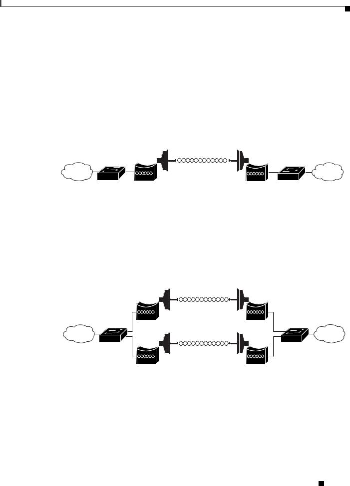
Point-to-Point Bridge Configuration
In a point-to-point bridge configuration, two bridges connect two remote LAN networks using a wireless communication link (see Figure 1-4). The bridge connected to the main LAN network is classified as a root bridge and the other bridge is classified as a non-root bridge.
Figure 1-4 Point-to-Point Bridge Configuration
117029
Port Aggregation or Redundancy Bridge Configuration
The port aggregation or redundancy bridge configuration (Figure 1-5) is used to provide increased bandwidth or backup redundancy communications between two LANs. Port aggregation or increased bandwidth occurs when both wireless links are used to simultaneously pass Ethernet traffic. Backup communication redundancy can be achieved with this configuration when one wireless bridge link is used only if the other wireless bridge link fails.
Figure 1-5 Port Aggregation or Redundancy Bridge Configuration
117020
Cisco Aironet 1300 Series Outdoor Access Point/Bridge Hardware Installation Guide
|
OL-5048-02 |
1-7 |
|
|
|

Chapter 1 Overview
Network Configuration Examples
Point-to-Multipoint Bridge Configuration
The point-to-multipoint bridge configuration (Figure 1-6) connects the main LAN network to multiple remote LAN networks. Wireless devices can also connect to the root bridge.
Figure 1-6 Point-to-Multipoint Bridge Configuration
117021
Access Point Configuration
When configured in access point mode, the unit can support remote workgroup bridges and local wireless client devices (see Figure 1-7). The access point/bridge defaults to a root access point role.
Figure 1-7 Access Point Configuration
|
|
|
|
|
|
|
|
|
|
|
|
|
|
|
|
|
|
|
|
|
|
|
|
|
|
|
|
Access |
|
|
|
|
|
|
|
|
|
|
|
|
|
|
|
|
Workgroup |
|
|||||||||
point |
|
|
|
|
|||||||||
|
|
|
bridge |
|
|||||||||
|
|
|
|
|
|
||||||||
|
|
|
|
|
|
|
|
|
|
|
|
|
|
117075
The access point configuration allows the wireless devices and the Ethernet-enabled wired devices using the workgroup bridge to pass Ethernet traffic to and from the main LAN.
Cisco Aironet 1300 Series Outdoor Access Point/Bridge Hardware Installation Guide
1-8 |
OL-5048-02 |
|
|

Chapter 1 Overview
Network Configuration Examples
Workgroup Bridge Configuration
When configured in the workgroup bridge mode, the unit provides a wireless connection for remote wired devices to a Cisco Aironet access point (see Figure 1-8) or to a Cisco Aironet bridge (see Figure 1-9).
Figure 1-8 Workgroup Bridge Configuration 1
|
|
|
|
|
|
|
|
|
|
|
|
|
|
|
|
|
|
|
|
|
|
|
|
|
|
|
|
Access |
|
|
|
|
|
|
|
|
|
|
|
|
|
|
|
|
Workgroup |
|
|||||||||
point |
|
|
|
|
|||||||||
|
|
|
bridge |
|
|||||||||
|
|
|
|
|
|
||||||||
|
|
|
|
|
|
|
|
|
|
|
|
|
|
117076
In Figure 1-8, the unit is configured in workgroup bridge mode and is associated to a Cisco Aironet access point as a wireless client device. This configuration allows the Ethernet-enabled devices to pass Ethernet traffic to and from the main LAN using the workgroup bridge.
Figure 1-9 Workgroup Bridge Configuration 2
|
|
|
|
|
|
|
|
|
|
|
|
|
|
|
|
|
|
|
|
|
|
|
|
|
|
|
|
|
|
|
|
|
|
|
|
|
|
|
Bridge |
|
|
|
Workgroup |
|
|||||||
|
|
|
|
bridge |
|
|||||||
|
|
|
|
|
|
|
|
|
|
|
|
|
117077
In Figure 1-9, the unit is configured in workgroup bridge mode and is associated to a Cisco Aironet root bridge as a wireless bridge device. This configuration allows the Ethernet-enabled devices pass Ethernet traffic to and from the main LAN using the workgroup bridge. The main advantage of this configuration is that the wireless communication link can be over a longer distance than an access point supports.
Typically, an access point can communicate over approximately a 1-mile range; however, the bridge-to-bridge wireless link can communicate over approximately a 21-mile range.
Cisco Aironet 1300 Series Outdoor Access Point/Bridge Hardware Installation Guide
|
OL-5048-02 |
1-9 |
|
|
|

Chapter 1 Overview
Network Configuration Examples
Cisco Aironet 1300 Series Outdoor Access Point/Bridge Hardware Installation Guide
1-10 |
OL-5048-02 |
|
|

C H A P T E R 2
Installation Overview
This chapter provides warnings, safety information, and information needed before you begin the installation of your access point/bridge system. This chapter includes the following sections:
•Safety Warnings, page 2-2
•Safety Information, page 2-3
•Unpacking the Access Point/Bridge, page 2-6
•Before Beginning the Installation, page 2-7
•Installation Summary, page 2-9
Cisco Aironet 1300 Series Outdoor Access Point/Bridge Hardware Installation Guide
|
OL-5048-02 |
2-1 |
|
|
|

Chapter 2 Installation Overview
Safety Warnings
Safety Warnings
Translated versions of the following safety warnings are provided in Appendix A, “Translated Safety Warnings.”
All Installations
Warning This warning symbol means danger. You are in a situation that could cause bodily injury. Before you work on any equipment, be aware of the hazards involved with electrical circuitry and be familiar with standard practices for preventing accidents. (To see translations of the warnings that appear in this publication, refer to the appendix “Translated Safety Warnings.”) Statement 84
Warning Do not operate your wireless network device near unshielded blasting caps or in an explosive environment unless the device has been modified to be especially qualified for such use.
Statement 245B
Warning In order to comply with international radio frequency (RF) exposure limits, dish antennas should be placed at a minimum of 8.7 inches (22 cm) from the bodies of all persons. Other antennas should be placed a minimum of 7.9 inches (20 cm) from the bodies of all persons. Statement 346
Warning Do not work on the system or connect or disconnect cables during periods of lightning activity.
Statement 1001
Warning This product relies on the building’s installation for short-circuit (overcurrent) protection. Ensure that the protective device is rated not greater than: 15A
Statement 1005
Warning This equipment must be grounded. Never defeat the ground conductor or operate the equipment in the absence of a suitably installed ground conductor. Contact the appropriate electrical inspection authority or an electrician if you are uncertain that suitable grounding is available. Statement 1024
Warning Ultimate disposal of this product should be handled according to all national laws and regulations.
Statement 1040
Cisco Aironet 1300 Series Outdoor Access Point/Bridge Hardware Installation Guide
2-2 |
OL-5048-02 |
|
|
Loading...