


 Loading...
Cisco Video Surveillance 4300 and 4500 High-Definition IP Cameras User Guide
Americas Headquarters
Cisco Systems, Inc. 170 West Tasman Drive
San Jose, CA 95134-1706 USA http://www.cisco.com Tel: 408 526-4000
800 553-NETS (6387) Fax: 408 527-0883
Text Part Number: OL-19609-04
NOTICE. ALL STATEMENTS, INFORMATION, AND RECOMMENDATIONS IN THIS MANUAL ARE BELIEVED TO BE ACCURATE BUT ARE PRESENTED WITHOUT WARRANTY OF ANY KIND, EXPRESS OR IMPLIED. USERS MUST TAKE FULL RESPONSIBILITY FOR THEIR APPLICATION OF ANY PRODUCTS.
THE SOFTWARE LICENSE AND LIMITED WARRANTY FOR THE ACCOMPANYING PRODUCT ARE SET FORTH IN THE INFORMATION PACKET THAT SHIPPED WITH THE PRODUCT AND ARE INCORPORATED HEREIN BY THIS REFERENCE. IF YOU ARE UNABLE TO LOCATE THE SOFTWARE LICENSE OR LIMITED WARRANTY, CONTACT YOUR CISCO REPRESENTATIVE FOR A COPY.
The Cisco implementation of TCP header compression is an adaptation of a program developed by the University of California, Berkeley (UCB) as part of UCB’s public domain version of the UNIX operating system. All rights reserved. Copyright © 1981, Regents of the University of California.
NOTWITHSTANDING ANY OTHER WARRANTY HEREIN, ALL DOCUMENT FILES AND SOFTWARE OF THESE SUPPLIERS ARE PROVIDED “AS IS” WITH ALL FAULTS. CISCO AND THE ABOVE-NAMED SUPPLIERS DISCLAIM ALL WARRANTIES, EXPRESSED OR IMPLIED, INCLUDING, WITHOUT LIMITATION, THOSE OF MERCHANTABILITY, FITNESS FOR A PARTICULAR PURPOSE AND NONINFRINGEMENT OR ARISING FROM A COURSE OF DEALING, USAGE, OR TRADE PRACTICE.
IN NO EVENT SHALL CISCO OR ITS SUPPLIERS BE LIABLE FOR ANY INDIRECT, SPECIAL, CONSEQUENTIAL, OR INCIDENTAL DAMAGES, INCLUDING, WITHOUT LIMITATION, LOST PROFITS OR LOSS OR DAMAGE TO DATA ARISING OUT OF THE USE OR INABILITY TO USE THIS MANUAL, EVEN IF CISCO OR ITS SUPPLIERS HAVE BEEN ADVISED OF THE POSSIBILITY OF SUCH DAMAGES.
Cisco and the Cisco Logo are trademarks of Cisco Systems, Inc. and/or its affiliates in the U.S. and other countries. A listing of Cisco's trademarks can be found at www.cisco.com/go/trademarks. Third party trademarks mentioned are the property of their respective owners. The use of the word partner does not imply a partnership relationship between Cisco and any other company. (1005R)
Cisco Video Surveillance 4300 and 4500 High-Definition IP Cameras User Guide
Copyright © 2009–2011 Cisco Systems, Inc. All rights reserved.

|
|
|
|
|
|
|
|
|
|
C O N T E N T S |
|||
|
|
|
Preface |
v |
|
|
|
|
|
|
|
|
|
|
|
|
Overview v |
|
|
|
|
|
|
|
|
|
|
|
|
|
Organization |
v |
|
|
|
|
|
|
|
|
|
|
|
|
Obtaining Documentation, Obtaining Support, and Security Guidelines v |
||||||||||
|
|
Overview |
|
|
|
|
|
|
|
|
|
|
|
C H A P T E R |
1 |
1-1 |
|
|
|
|
|
|
|
|
|
||
|
|
|
IP Camera Features |
1-1 |
|
|
|
|
|
|
|
||
|
|
|
IP Camera Physical Details |
1-2 |
|
|
|
|
|
|
|||
|
|
|
DC Auto Iris Lens Connector Pinouts |
1-6 |
|
|
|
|
|||||
|
|
|
Package Contents |
1-6 |
|
|
|
|
|
|
|
||
|
|
Getting Started |
|
|
|
|
|
|
|
|
|
||
C H A P T E R |
2 |
2-1 |
|
|
|
|
|
|
|
|
|||
|
|
|
Installing the IP Camera |
2-1 |
|
|
|
|
|
|
|||
|
|
|
Performing the Initial Setup of the IP Camera |
2-5 |
|
|
|
||||||
|
|
|
Accessing the IP Camera |
2-6 |
|
|
|
|
|
|
|||
|
|
|
Understanding the IP Camera User Interface |
2-7 |
|
|
|
||||||
|
|
|
IP Camera Window Links 2-7 |
|
|
|
|
|
|||||
|
|
|
IP Camera Windows |
2-8 |
|
|
|
|
|
|
|||
|
|
|
Adjusting Back Focus on the IP Camera |
2-9 |
|
|
|
|
|||||
|
|
|
Powering the IP Camera On or Off 2-10 |
|
|
|
|
||||||
|
|
|
Resetting the IP Camera |
2-10 |
|
|
|
|
|
|
|||
|
|
Configuring and Managing the IP Camera 3-1 |
|||||||||||
C H A P T E R |
3 |
||||||||||||
|
|
|
Accessing Navigating the Configuration Windows 3-1 |
||||||||||
|
|
|
Feature Setup Windows |
3-2 |
|
|
|
|
|
|
|||
|
|
|
Streaming Settings Window |
3-3 |
|
|
|
|
|
||||
|
|
|
Camera Settings Window |
3-6 |
|
|
|
|
|
||||
|
|
|
Video Overlay Settings Window |
3-8 |
|
|
|
|
|||||
|
|
|
IO Ports Settings Window |
3-8 |
|
|
|
|
|
||||
|
|
|
Pan Tilt Settings Window |
3-9 |
|
|
|
|
|
||||
|
|
|
Event Notification Window |
3-10 |
|
|
|
|
|
||||
|
|
|
Patrol Sequence Window |
3-14 |
|
|
|
|
|
||||
|
|
|
Analytics Windows |
3-16 |
|
|
|
|
|
|
|||
|
|
|
|
|
|
Cisco Video Surveillance 4300 and 4500 High-Definition IP Cameras User Guide |
|
|
|
||||
|
|
|
|
|
|
|
|||||||
|
|
|
|
|
|
|
|
|
|
|
|
|
|
|
OL-19609-04 |
|
|
|
|
|
|
|
|
|
iii |
|
|
|
|
|
|
|
|
|
|
|
|
|
|||

Contents
Network Setup Windows |
3-16 |
|
|
Basic Settings Window |
|
3-16 |
|
IP Addressing Window |
|
3-17 |
|
Time Settings Window |
|
3-18 |
|
Discovery Settings Window |
3-20 |
||
SNMP Settings Window |
3-21 |
||
802.1x Settings Window |
3-23 |
||
IP Filter Settings Window |
3-24 |
||
QoS Settings Window |
3-25 |
|
|
Administration Windows |
3-26 |
|
|
Account Initialization Window |
3-26 |
||
User Settings Window |
|
3-28 |
|
Maintenance Settings Window 3-29 |
|||
Firmware Settings Window |
3-31 |
||
Device Processes Window 3-32 |
|||
Password Complexity Window |
3-33 |
||
Log Windows 3-33 |
|
|
|
Log Setup Settings Window |
3-33 |
||
Local Log Window 3-35 |
|
|
|
C H A P T E R |
4 |
Viewing Live Video 4-1 |
|
|
Troubleshooting 5-1 |
C H A P T E R |
5 |
|
|
|
|
I N D E X |
|
|
Cisco Video Surveillance 4300 and 4500 High-Definition IP Cameras User Guide
|
iv |
OL-19609-04 |
|
|
|

Preface
Overview
This document, Cisco Video Surveillance IP Camera User Guide, provides information about installing, configuring, using, managing, and troubleshooting the Cisco 4000 Series Video Surveillance High-Definition IP Cameras.
Organization
This manual is organized as follows:
Chapter 1, “Overview” |
Provides an overview of the IP camera and its features |
|
|
Chapter 2, “Getting Started” |
Provides instructions for installing and performing |
|
the initial setup of the IP camera, accessing and |
|
understanding the IP camera user interface, powering |
|
the IP camera on and off, resetting the IP camera, and |
|
adjusting its back focus |
|
|
Chapter 3, “Configuring and Managing the IP |
Explains how to configure, manage, and administer |
Camera” |
the IP camera through the web-based configuration |
|
pages |
|
|
Chapter 4, “Viewing Live Video” |
Explains how to view live video from the IP camera |
|
|
Chapter 5, “Troubleshooting” |
Provides basic troubleshooting information |
|
|
Obtaining Documentation, Obtaining Support, and Security
Guidelines
For information about obtaining documentation, submitting a service request, and gathering additional information, see the monthly What’s New in Cisco Product Documentation, which also lists all new and revised Cisco technical documentation, at:
http://www.cisco.com/en/US/docs/general/whatsnew/whatsnew.html
Cisco Video Surveillance 4300 and 4500 High-Definition IP Cameras User Guide
|
OL-19609-04 |
v |
|

Preface
Subscribe to the What’s New in Cisco Product Documentation as a Really Simple Syndication (RSS) feed and set content to be delivered directly to your desktop using a reader application. The RSS feeds are a free service and Cisco currently supports RSS version 2.0.
Cisco Video Surveillance 4300 and 4500 High-Definition IP Cameras User Guide
|
vi |
OL-19609-04 |
|
|
|

C H A P T E R 1
Overview
This chapter provides an overview of the Cisco 4000 Series Video Surveillance High-Definition IP Cameras and their features. These IP cameras include:
•CIVS-IPC-4300—High-definition digital camera that is suitable for a wide range of video surveillance applications
•CIVS-IPC-4500—Identical features to the CIVS-IPC-4300 model with the addition of digital signal processor (DSP) capabilities that are used for the Cisco video analytics feature
Note The CIVS-IPC-4300 model is not designed to be upgraded with a DSP.
This chapter includes these topics:
•IP Camera Features, page 1-1
•IP Camera Physical Details, page 1-2
•DC Auto Iris Lens Connector Pinouts, page 1-6
•Package Contents, page 1-6
IP Camera Features
The Cisco Video Surveillance IP Camera offers a feature-rich digital camera solution for a video surveillance system. The camera provides high-definition (HD) video and simultaneous H.264 and MJPEG compression, streaming up to 30 frames per second (fps) at 1080p (1920 x 1080) resolution, and 60 fps at 720p (1280 x 720) resolution. Contact closures and two-way audio allow integration with microphones, speakers, and access control systems.
In addition, the IP camera provides networking and security capabilities, including multicast support, hardware-based Advanced Encryption Standard (AES), and hardware-based Data Encryption Standard/Triple Data Encryption Standard (DES/3DES) encryption. The camera can be powered through an external power supply or by integrated Power over Ethernet (PoE).
The IP camera includes the following key features:
•H.264 and MJPEG compression—The IP camera can generate H.264 and MJPEG streams simultaneously.
•Progressive scan video—The camera captures each frame at its entire resolution using progressive scan rather than interfaced video capture, which captures each field of video.
•Day/night switch support—An IR-cut filter provides increased sensitivity in low-light conditions.
Cisco Video Surveillance 4300 and 4500 High-Definition IP Cameras User Guide
|
OL-19609-04 |
1-1 |
|
|
|

Chapter 1 Overview
IP Camera Physical Details
•Two-way audio communication—Audio can be encoded with the video. With the internal or optional external microphone and optional external speaker, you can communicate with people at the IP camera location while you are in a remote location and viewing images from the IP camera.
•Multi-protocol support—Supports these protocols: DHCP, FTP, HTTP, HTTPS, NTP, RTP, RTSP, SMTP, SNMP v2 and v3, SSL/TLS, and TCP/IP.
•Web-based management—You perform ongoing administration and management of the IP camera through web-based configuration menus.
•Motion detection—The IP camera can detect motion in user-designated fields of view by analyzing changes in pixels and generate an alert if motion is detected.
•Flexible scheduling—You can configure the IP camera to respond to events that occur within a designated schedule.
•Syslog support—The IP camera can send log data to a Syslog server.
•IP address filter—You can designate IP addresses that can access the IP camera and IP addresses that cannot access the IP camera.
•User-definable HTTP/ HTTPS port number—Allows you to define the port that is used to connect to the camera through the Internet.
•DHCP support—The IP camera can automatically obtain its IP addresses in a network in which DHCP is enabled.
•Network Time Protocol (NTP) support—Allows the IP camera to calibrate its internal clock with a local or Internet time server.
•Support for C and CS mount lenses—The IP camera supports a variety of C and CS mount lenses.
•RS-485/PTZ support—The IP camera supports Pelco D protocol, which enables PTZ functions when used with a supported motorized zoom lens, external pan/tilt mount, and control device.
•Power options—The IP camera can be powered with 12 volts DC or 24 volts AC, which is provided through an optional external power adapter, or through PoE (802.3af), which is provided through a supported switch.
•Camera access control—You can control access to IP camera configuration windows and live video by configuring various user types and log in credentials.
•Video analytics (CIVS-IPC-4500 only)—Provides an intuitive interface and tools for video analysis.
IP Camera Physical Details
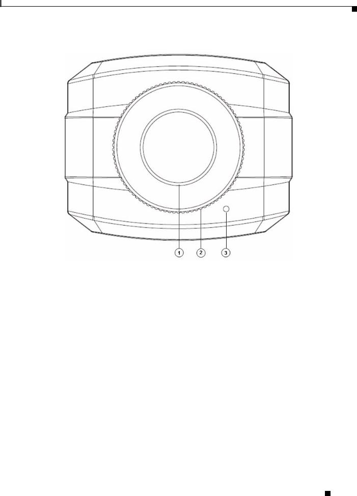
The IP camera includes a reset button, built-in microphone, status LEDs, several ports for connecting external devices, and two threaded mounting holes, one on the bottom and one on the top.
Figure 1-1 and the table that follows describe the items on the front of the IP camera.
Cisco Video Surveillance 4300 and 4500 High-Definition IP Cameras User Guide
1-2 |
OL-19609-04 |
|
|
Chapter 1 Overview
IP Camera Physical Details
Figure 1-1 Front of IP Camera
1 |
Lens opening |
The IP camera supports a variety of C and CS mount lenses, which |
|
|
attach here. |
|
|
For best performance, Cisco recommends that you use a DC auto |
|
|
iris lens. |
|
|
|
2 |
Focus ring |
Allows you to adjust the back focus of the IP camera. |
|
|
You must loosen the focus ring hex screw on the bottom of the IP |
|
|
camera before you can rotate the focus ring. For instructions, see |
|
|
the “Adjusting Back Focus on the IP Camera” section on page 2-9. |
|
|
|
3 |
Microphone |
Captures audio. |
|
|
There also is a connection for an optional external microphone on |
|
|
the rear of the IP camera. |
|
|
|
Cisco Video Surveillance 4300 and 4500 High-Definition IP Cameras User Guide
|
OL-19609-04 |
1-3 |
|
|
|

Chapter 1 Overview
IP Camera Physical Details
Figure 1-2 and the table that follows describe the items on the rear of the IP camera.
Figure 1-2 Rear of IP Camera
|
1 |
Power LED |
Lights bright when the IP camera is powering up. Lights dim when |
||||
|
|
|
|
|
|
the camera is IP operating |
|
|
|
|
|
||||
2 |
Audio Port |
Allows the connection of the audio Y cable that is provided with |
|||||
|
|
|
|
|
|
the IP camera. You can connect an optional external speaker, |
|
|
|
|
|
|
|
optional external microphone (with pre-amplifier), or both devices |
|
|
|
|
|
|
|
through this cable. |
|
|
|
|
|
|
|
Each device connects to the audio cable through a standard 3.5 mm |
|
|
|
|
|
|
|
mini phone jack. A speaker connects to the green jack, which is |
|
|
|
|
|
|
|
labeled “Audio Out.” A microphone connects to the pink jack, |
|
|
|
|
|
|
|
which is labeled “Audio In.” Microphones and speakers that are |
|
|
|
|
|
|
|
designed for use with PCs usually are compatible with this input |
|
|
|
|
|
|
|
jack. |
|
|
|
|
|
|
|
Connecting an external microphone disables the internal |
|
|
|
|
|
|
|
microphone on the IP camera. |
|
|
|
|
|
||||
3 |
PoE LED |
Indicates information about PoE as follows: |
|||||
|
|
|
|
|
|
• Lit green—PoE connection is detected |
|
|
|
|
|
|
|
• Off—PoE connection is not detected |
|
|
|
|
|
|
|
|
|
|
|
|
Cisco Video Surveillance 4300 and 4500 High-Definition IP Cameras User Guide |
||||
|
|
|
|||||
|
|
|
|
|
|
|
|
|
1-4 |
|
|
|
|
OL-19609-04 |
|
|
|
|
|
|
|
||
Chapter 1 Overview
IP Camera Physical Details
4 |
LAN port |
Accepts a standard LAN cable to connect the IP camera to a |
|
|||
|
|
100BaseT hub, router, or switch. |
|
|||
|
|
|
|
|||
5 |
Network Activity LED |
Indicates information about the network connections as follows: |
|
|||
|
|
|
• Lit amber—LAN connection is detected |
|
||
|
|
|
• Off—LAN connection is not detected |
|
||
|
|
|
• Blinking—Data is being transmitted or received via the LAN |
|
||
|
|
|
connection |
|
||
|
|
|
|
|||
6 |
Power input |
Provides for the connection of an optional 12 V, 1 amp DC power |
|
|||
|
|
adapter or 24 VAC power adapter. |
|
|||
|
|
|
|
|
|
|
|
|
Caution Use only the Cisco specified power supply adapter. |
|
|||
|
|
|
|
|
||
|
|
|
|
|||
7 |
Reset button |
Recessed button that reboots the IP camera or resets it to a default |
|
|||
|
|
state. You can use a pin or paper clip to depress it. It can be used |
|
|||
|
|
any time that the IP camera is on and can have various effects, as |
|
|||
|
|
described in the “Resetting the IP Camera” section on page 2-10. |
|
|||
|
|
|
|
|||
8 |
GPIO ports |
General purpose input/output (GPIO) terminal block that includes |
|
|||
|
|
2 input ports (labeled DI1, DI2), 2 output ports (labeled DO1, |
|
|||
|
|
DO2), a grounding port (labeled GND), and a a 5-pin RS-232 port. |
|
|||
|
|
|
|
|||
9 |
USB port |
Not supported. |
|
|||
|
|
|
|
|
|
|
Figure 1-3 and the table that follows describe the item on the side of the IP camera.
Figure 1-3 Side of IP Camera
|
1 |
DC auto iris lens connector |
Connection for cable from DC auto iris lens |
||||
|
|
|
|
|
|
|
|
|
|
|
Cisco Video Surveillance 4300 and 4500 High-Definition IP Cameras User Guide |
|
|
||
|
|
|
|
||||
|
|
|
|
|
|
|
|
|
OL-19609-04 |
|
|
|
1-5 |
|
|
|
|
|
|
|
|||
Chapter 1 Overview
DC Auto Iris Lens Connector Pinouts
DC Auto Iris Lens Connector Pinouts
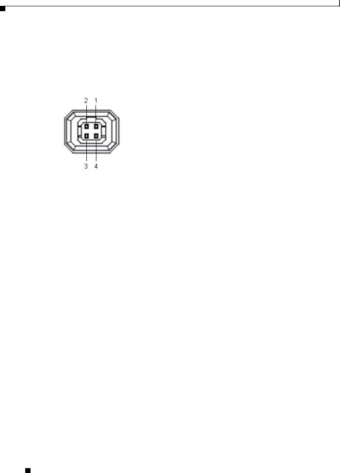
Figure 1-4 and the table that follows describe the pinouts of the DC auto iris lens connector on the IP camera.
Figure 1-4 DC Auto Iris Lens Connector Pinouts
Pin |
Function |
|
|
1 |
Damp – |
|
|
2 |
Damp + |
|
|
3 |
Drive + |
|
|
4 |
Drive – |
|
|
Package Contents
The the Cisco Video Surveillance IP Camera package includes these items:
•Camera
•Lens opening dust cap
•USB port cover
•Audio Y cable, 3.5 mm male mono jack / dual 3.5 mm female mono jacks, for connecting an external speaker and microphone
•Terminal block for power connection
•C mount lens adaptor
•0.9 mm Allen wrench for unlocking and locking the focus ring
•Regulatory Compliance and Safety Information
•Quick Start Guide
Cisco Video Surveillance 4300 and 4500 High-Definition IP Cameras User Guide
1-6 |
OL-19609-04 |
|
|

C H A P T E R 2
Getting Started
This chapter provides instructions for installing and performing the initial setup of the Cisco Video Surveillance IP Camera. It also describes how to access the IP camera through a web browser so that you can configure it or view video from it, and how to perform other important tasks.
This chapter includes these topics:
•Installing the IP Camera, page 2-1
•Performing the Initial Setup of the IP Camera, page 2-5
•Accessing the IP Camera, page 2-6
•Understanding the IP Camera User Interface, page 2-7
•Adjusting Back Focus on the IP Camera, page 2-9
•Powering the IP Camera On or Off, page 2-10
•Resetting the IP Camera, page 2-10
Installing the IP Camera
This section describes how to install the IP camera. Before installing, review these guidelines:
•The IP camera requires a network cable and a connection to a standard 100BaseT hub, router, or switch. To power the IP camera with Power over Ethernet (PoE), a switch must be 802.3af compliant.
•If you are using the IP camera on a network connection that does not provide PoE, you must use a Cisco 12 VDC power adapter (Cisco part number CIVS-PWRPAC-12V) or a third-party 24 VAC power adapter.
•If you are using an external speaker, microphone, input device, output device, or pan/tilt control device, you must configure additional settings after installing and performing the initial set up of the IP camera before the external device can fully operate. For detailed information about these settings, see Chapter 3, “Configuring and Managing the IP Camera.”
•If you do not connect an external device (speaker, microphone, analog video display, input device, output device, or pan/tilt control device) when you perform the following installation procedure, you can install any of these devices later.
Warning Installation of the equipment must comply with local and national electrical codes. Statement 1074
Cisco Video Surveillance 4300 and 4500 High-Definition IP Cameras User Guide
|
OL-19609-04 |
2-1 |
|
|
|

Chapter 2 Getting Started
Installing the IP Camera
Warning The power supply must be placed indoors. Statement 331
Note If you use the IP camera outdoors, place the camera and the power supply in a suitable NEMA enclosure.
Warning This product must be connected to a power-over-ethernet (PoE) IEEE 802.3af compliant power source or an IEC60950 compliant limited power source. Statement 353
Caution Inline power circuits provide current through the communication cable. Use the Cisco provided cable or a minimum 24AWG communication cable.
Note The power adapter that you use with the IP camera must provide power that is within +/–10% of the required power.
Note The equipment is to be connected to a Listed class 2, limited power source.
To install the IP camera, follow the steps in Table 2-1. For illustrations of the connectors and ports that the steps refer to, see the “IP Camera Physical Details” section on page 1-2.
. |
|
|
Table 2-1 |
Installing the IP Camera |
|
|
|
|
|
Action |
Explanation |
|
|
|
Step 1 |
Attach a lens to the lens opening on the IP camera. |
• If you are using a CS mount lens, screw the lens into |
|
|
the lens opening. The IP camera accepts CS-mount |
|
|
lenses with a lens protrusion of up to 5 mm. |
|
|
• If you are using a C mount lens, screw the C mount |
|
|
lens adapter that is supplied with the IP camera into |
|
|
the lens opening, then screw the lens into the adapter. |
|
|
Ensure that the lens is clean because any dirt may degrade |
|
|
the quality of video images. |
|
|
Note Save the lens opening dust cap and replace the dust |
|
|
cap if you remove the lens. |
|
|
|
Step 2 |
If you are using a DC auto iris lens, connect its cable to |
For best performance, Cisco recommends that you use a |
|
the DC auto iris lens connector on the IP camera. |
DC auto iris lens. |
|
|
|
Cisco Video Surveillance 4300 and 4500 High-Definition IP Cameras User Guide
2-2 |
OL-19609-04 |
|
|

Chapter 2 Getting Started
Installing the IP Camera
Table 2-1 |
Installing the IP Camera (continued) |
|
|
|
|
|
Action |
Explanation |
|
|
|
Step 3 |
Optional. Use the audio Y cable that is provided with |
The audio cable that is provided with the IP includes two |
|
the IP camera to connect a speaker, microphone, or both |
plugs. The cable from an external speaker connects to the |
|
devices to the audio port on the rear of the IP camera. |
Audio Out plug on the audio cable. The cable from an |
|
|
external microphone connects to the Audio In plug on the |
|
|
audio cable. |
|
|
A speaker plays audio that is captured by a microphone |
|
|
that is attached to the PC on which you view video from |
|
|
the camera. |
|
|
Place the external microphone in a location that allows it |
|
|
to capture the audio that you want. |
|
|
Note By default, the IP camera does not transmit or |
|
|
receive audio. To enable and configure audio, see |
|
|
the “Streaming Settings Window” procedure on |
|
|
page 3-3. |
|
|
|
Step 4 |
Optional. Use the GPIO ports on the rear of the IP |
You can connect up to two input devices and two output |
|
camera to connect external devices that trigger alarms |
devices to these ports: |
|
(connect through input ports) or respond to alarms |
DI1—Alarm input 1 |
|
(connect through output ports). |
|
|
DI2—Alarm input 2 |
|
|
|
|
|
|
DO1—Alarm output 1 |
|
|
DO2—Alarm output 2 |
|
|
GND—Ground (for use if needed) |
|
|
|
Step 5 |
Optional. Use the RS-232 ports on the rear of the IP |
A RS-232 cable fits into the ports in one way. Make sure |
|
camera to connect a control device (motorized housing) |
to insert it properly. |
|
that supports the Pelco D protocol. |
|
|
|
|
Step 6 |
Connect an STP (shielded twisted pair) Category 5 or |
If your network provides PoE, the IP camera powers on. |
|
higher network cable to the LAN port on the back of the |
Skip to Step 8. |
|
camera and to a 100BaseT hub, router, or switch. |
|
|
|
|
Cisco Video Surveillance 4300 and 4500 High-Definition IP Cameras User Guide
|
OL-19609-04 |
2-3 |
|
|
|

Chapter 2 Getting Started
Installing the IP Camera
Table 2-1 |
Installing the IP Camera (continued) |
|
|
|
|
|
Action |
Explanation |
|
|
|
Step 7 |
If you are using the IP camera on a network connection |
First, connect the bare wires at the end of the power |
|
that does not provide PoE, connect the optional 12 VDC |
adapter to the terminal block that is provided with the IP |
|
or 24 VAC power adapter. |
camera: |
|
|
• With the screws on the terminal block facing down, |
|
|
take either of these actions: |
|
|
– For a 12 VDC power adapter—Put the positive |
|
|
wire into the slot at the right rear of the terminal |
|
|
block, put the negative wire into the middle slot |
|
|
and put the ground wire in the left slot. (On the |
|
|
Cisco power adapters, the positive wire has a |
|
|
white stripe and the negative wire has no stripe.) |
|
|
– For a 24 VAC power adapter—Put one wire into |
|
|
the into the slot at the right rear of the terminal |
|
|
block and put the other wire into the middle slot. |
|
|
There is polarity, so either wire can go into either |
|
|
slot. |
|
|
• Use a small flat-head screwdriver to tighten the |
|
|
screws on the bottom of the terminal block so that the |
|
|
power adapter wires are attached securely. |
|
|
Note The power adapter may include an attached |
|
|
terminal block that does not fit the IP camera. If |
|
|
so, remove that terminal block and replace it with |
|
|
the one that is provided with the IP camera. |
|
|
Next, plug the terminal block into the power input port on |
|
|
back of the IP camera. The terminal block fits into the |
|
|
input port in one way. Make sure that the tabs on the |
|
|
terminal block face the bottom of the IP camera. |
|
|
Finally, plug the power adapter into an electrical outlet. |
|
|
The IP camera powers up. |
|
|
|
Step 8 |
Check the LEDs on the IP camera. |
• The Ready LED lights brightly while the IP camera |
|
|
starts up. After a few minutes, the Ready LED flashes |
|
|
briefly then dims. |
|
|
• The Network LED should be on. |
|
|
|
Step 9 |
Mount the IP camera in the desired location. |
Connect the mounting device to the threaded mounting |
|
|
hole on the bottom or top of the IP camera, depending on |
|
|
your installation requirement. |
|
|
|
After you install the IP camera, follow the instructions in the “Performing the Initial Setup of the IP Camera” section on page 2-5 to access and configure the camera.
Cisco Video Surveillance 4300 and 4500 High-Definition IP Cameras User Guide
2-4 |
OL-19609-04 |
|
|

Chapter 2 Getting Started
Performing the Initial Setup of the IP Camera
Performing the Initial Setup of the IP Camera
After you install IP camera as described in the “Installing the IP Camera” section on page 2-1, or after you perform a factory reset procedure, you must access the IP camera and make initial configuration settings. These settings include administrator and root passwords, and whether the IP camera can be accessed through an HTTP connection in addition to the default HTTPS (HTTP secure) connection.
To make these configuration settings, you connect to the IP camera from any PC that is on the same network as the IP camera. The PC must meet these requirements:
•Operating system—Microsoft Windows XP with Service Pack 2 or 3
•Browser—Internet Explorer 6.0 with Service Pack 2 or higher
In addition, you must know the IP address of the IP camera. By default, when the IP camera powers on, it attempts to obtain an IP address from a DHCP server in your network. If the camera cannot obtain an IP address through DCHP within 90 seconds, it uses a default IP address of 192.168.0.100.
To connect to the IP camera for the first time and make initial configuration settings, perform the following steps. You can change these configuration settings in the future as described in Chapter 3, “Configuring and Managing the IP Camera.”
Before you Begin
The Microsoft .NET Framework version 2.0 or later must be installed on the PC that you use to connect to the IP camera. You can download the .NET Framework from the Microsoft website.
Procedure
Step 1 Start Internet Explorer, enter HTTPS://ip_address in the address field, and press Enter.
Replace ip_address with the IP address that the IP camera obtained through DHCP or, if the camera was unable to obtain this IP address, enter 192.168.0.100.
The Account window appears.
Step 2 In the Set Password and Verify Password fields in the Admin column, enter a password for the IP camera administrator.
You must enter the same password in both fields. The password is case sensitive and must contain at least eight characters, which can be letters, numbers, and special characters, but no spaces. Special characters are: ! " # $ % & ' ( ) * + , - . : ; < = > ? @ [ \ ] ^ _ ` { | } ~.
Step 3 In the Set Password and Verify Password fields in the Root column, enter a password that is used when accessing the IP camera through a Secure Shell (SSH) connection.
You must enter the same password in both fields. The password is case sensitive and must contain at least eight characters, which can be letters, numbers, and special characters, but no spaces. Special characters are: ! " # $ % & ' ( ) * + , - . : ; < = > ? @ [ \ ] ^ _ ` { | } ~.
You use the root password if you need to troubleshoot the IP camera through a SSH connection with the assistance of the Cisco Technical Assistance Center.
Step 4 In the HTTP area, click the HTTP radio button if you want to allow both HTTP and HTTPS connections to the IP camera.
The default setting is HTTPS, which allows only HTTPS (secure) connections to the IP camera.
Step 5 Click Apply.
The IP camera reboots.
Cisco Video Surveillance 4300 and 4500 High-Definition IP Cameras User Guide
|
OL-19609-04 |
2-5 |
|
|
|

Chapter 2 Getting Started
Accessing the IP Camera
Step 6 After the IP camera reboots, start Internet Explorer and, in the Address field, enter the following:
protocol://ip_address
where:
•protocol is HTTPS or HTTP. (You can use HTTP only if you enabled it in Step 4.)
•ip_address is the IP address that you used in Step 1.
Step 7 If you are prompted to install ActiveX controls, which are required to view video from the IP camera, follow the on-screen prompts to do so.
The Home window for the IP Camera appears. For information about this window, see the “Understanding the IP Camera User Interface” procedure on page 2-7.
Accessing the IP Camera
After you perform the initial configuration as described in the “Performing the Initial Setup of the IP Camera” section on page 2-5, follow the steps in this section each time that you want to access the IP camera windows to make configuration settings, view live video, or perform other activities.
You access these windows by connecting to the IP camera from any PC that is on the same network as the IP camera and that meets these requirements:
• Operating system—Microsoft Windows XP with Service Pack 2 or 3
•Browser—Internet Explorer 6.0 with Service Pack 2 or higher You need this information to access the IP camera windows:
•IP address of the IP camera. By default, the IP camera attempts to obtain an IP address from a DHCP server in your network. If the IP camera cannot obtain an IP address through DHCP within 90 seconds of powering up or resetting, it uses the default IP address of 192.168.0.100.
•Port number, if other than the default value. Default port numbers for the IP camera are 443 for HTTPS and 80 for HTTP. The IP camera administrator can configure an HTTPS port and an HTTP port as described in the “Account Initialization Window” section on page 3-26.
•Your user name and password for the IP camera. The IP camera administrator configures user names and passwords as described in the “User Settings Window” section on page 3-28.
To access the IP camera windows, perform the following these steps.
Before you Begin
The Microsoft .NET Framework version 2.0 or later must be installed on the PC that you use to connect to the IP camera. You can download the .NET Framework from the Microsoft website.
Procedure
Step 1 Start Internet Explorer and enter the following in the address field:
protocol://ip_address:port_number
where:
•protocol is HTTPS for a secure connection or HTTP for a non-secure connection. You can use HTTP only if you configure the camera to accept non-secure HTTP connections as described in the “Performing the Initial Setup of the IP Camera” section on page 2-5.
Cisco Video Surveillance 4300 and 4500 High-Definition IP Cameras User Guide
2-6 |
OL-19609-04 |
|
|

Chapter 2 Getting Started
Understanding the IP Camera User Interface
•ip_address is the IP address of the IP camera. The default IP address is 192.168.0.100.
•port_number is the port number that is used for HTTPS or HTTP connections to the IP camera. You do not need to enter a port number if you are connecting through the default HTTPS port 443 or the default HTTP port 80.
For example,
•Enter the following for a secure connection if the IP address is 192.168.0.100 and the HTTPS port number is 443:
https://192.168.0.100
•Enter the following for a secure connection if the IP address is 203.70.212.52 and the HTTPS port number is 1024:
https://203.70.212.52:1024
•Enter the following for a non-secure connection if the IP address is 203.70.212.52 and the HTTP port number is 80:
http://203.70.212.52
•Enter the following for a non-secure connection if the IP address is 203.70.212.52 and the HTTP port number is 1024:
http://203.70.212.52:1024
Step 2 Enter your IP camera user name and password in the Username and Password fields, then click Login.
To log in as the IP camera administrator, enter the user name admin (which is case sensitive) and the password that is configured for the administrator. To log in as a user, enter the user name and password that are configured for the user.
The Home window for the IP Camera appears.
Understanding the IP Camera User Interface
After you log in to the IP camera as described in the “Accessing the IP Camera” section on page 2-6, you can access the IP camera windows and perform a variety of administrative and user procedures.
The links and activities that you can see and access in the IP camera windows depend on your IP camera privilege level. Privilege levels are configured as described in the “User Settings Window” section on page 3-28 and include the following:
•Administrator—Can access all IP camera windows, features, and functions.
•Viewer—Can access the Camera Video/Control window with limited controls, and can access the Refresh, Logout, About, and Help links from that window.
IP Camera Window Links
The IP Camera user interface includes links that you use to access various windows and perform other activities. Table 2-2 describes each link and lists the IP camera privilege level that you must have to access the link.
Cisco Video Surveillance 4300 and 4500 High-Definition IP Cameras User Guide
|
OL-19609-04 |
2-7 |
|
|
|

Chapter 2 Getting Started
Understanding the IP Camera User Interface
Table 2-2 |
Links in the IP Camera Windows |
|
|
|
|
|
|
Link |
|
Description |
Privilege Level |
|
|
|
|
Refresh |
|
Updates the information in the window that is currently displayed. |
Administrator |
|
|
|
User |
|
|
|
|
Home |
|
Displays the Home window. |
Administrator |
|
|
|
|
View Video |
|
Displays the Camera Video/Control window. |
Administrator |
|
|
You may be prompted to install ActiveX controls when trying to |
User |
|
|
access this window for the first time. ActiveX controls are required |
|
|
|
to view video from the IP camera. Follow the on-screen prompts to |
|
|
|
install ActiveX controls. |
|
|
|
|
|
Setup |
|
Provides access to the configuration menus for the IP camera. |
Administrator |
|
|
|
|
Logout |
|
Logs you out from the IP camera. |
Administrator |
|
|
|
User |
|
|
|
|
About |
|
Displays a pop-up window with model, version, and copyright |
Administrator |
|
|
information for the IP camera. |
User |
|
|
|
|
|
|
|
|
Help |
|
Displays reference information for the window that is currently |
Administrator |
|
|
displayed. |
User |
|
|
|
|
|
|
|
|
IP Camera Windows
The IP camera user interface includes these main windows:
• Home window—Displays the information that is described in Table 2-3.
|
|
|
|
Table 2-3 |
Home Window Information |
||
|
|
|
|
|
|
|
|
|
|
|
|
Field |
|
Description |
|
|
|
|
|
|
|
|
|
|
|
|
|
General Information |
|
|
|
|
|
|
|
|
|
|
|
|
|
|
|
ID |
|
Identifier of the IP camera. To configure the ID, see the “Basic Settings |
|
|
|
|
|
|
|
Window” section on page 3-16. |
|
|
|
|
|
|
|
|
|
|
|
|
|
Name |
|
Name of the IP camera. To configure the name, see the “Basic Settings |
|
|
|
|
|
|
|
Window” section on page 3-16. |
|
|
|
|
|
|
|
|
|
|
|
|
|
Current Time |
|
Current date and time of the IP camera. To set the date and time, see the |
|
|
|
|
|
|
|
“Time Settings Window” section on page 3-18 |
|
|
|
|
|
|
|
|
|
|
|
|
|
S/N |
|
Serial number of the IP camera. |
|
|
|
|
|
|
|
|
|
|
|
|
|
Firmware |
|
Version of the firmware that is installed on the IP camera. |
|
|
|
|
|
|
|
|
|
|
|
|
|
Codec |
|
Version of the codec that is running on the IP camera. |
|
|
|
|
|
|
|
|
|
|
|
|
|
Part Number |
|
Cisco manufacturing part number of the IP camera. |
|
|
|
|
|
|
|
||
|
|
|
|
Top Assembly Revision |
Cisco assembly revision number. |
||
|
|
|
|
|
|
|
|
|
|
|
|
Network Status |
|
|
|
|
|
|
|
|
|
|
|
|
|
|
|
MAC Address |
|
MAC address of the IP camera. |
|
|
|
|
|
|
|
||
|
|
|
Cisco Video Surveillance 4300 and 4500 High-Definition IP Cameras User Guide |
||||
|
|
|
|||||
|
|
|
|
|
|
|
|
|
2-8 |
|
|
|
|
OL-19609-04 |
|
|
|
|
|
|
|
||
Chapter 2 Getting Started
Adjusting Back Focus on the IP Camera
Table 2-3 |
Home Window Information (continued) |
|
|
|
|
Field |
|
Description |
|
|
|
Configuration Type |
Method by which the IP camera obtains its IP address. To configure this |
|
|
|
method, see the “IP Addressing Window” section on page 3-17. |
|
|
|
LAN IP |
|
IP address of the LAN to which the IP camera is connected. To configure this |
|
|
IP address, see the “IP Addressing Window” section on page 3-17. |
|
|
|
Subnet Mask |
|
Subnet mask of the LAN to which the IP camera is connected. To configure |
|
|
the subnet mask, see the “IP Addressing Window” section on page 3-17. |
|
|
|
Gateway Address |
IP address of the gateway through which the IP camera is connected. To |
|
|
|
configure this IP address, see the “IP Addressing Window” section on |
|
|
page 3-17. |
|
|
|
Primary DNS |
|
IP address of the primary DNS server, if configured for the IP camera. To |
|
|
configure a primary DNS server, see the “IP Addressing Window” section |
|
|
on page 3-17. |
|
|
|
Secondary DNS |
IP address of the secondary DNS server, if configured for the IP camera. To |
|
|
|
configure a secondary DNS server, see the “IP Addressing Window” section |
|
|
on page 3-17. |
|
|
|
IO Port Status |
|
|
|
|
|
Input Port 1 |
|
Current state of input port 1 on the IP camera. |
|
|
|
Input Port 2 |
|
Current state of input port 2 on the IP camera. |
|
|
|
Output Port 1 |
|
Current state of output port 1 on the IP camera. |
|
|
|
Output Port 1 |
|
Current state of output port 2 on the IP camera. |
|
|
|
Channel 1 and Channel 2 |
||
|
|
|
User |
|
IP camera user name of each user who is accessing the primary video stream |
|
|
(Channel 1) or the secondary video stream (Channel 2) through a client PC |
|
|
or a third-party device. |
|
|
Be default, users appear in order of start time. To displays users in ascending |
|
|
order of any information in any corresponding column, click the column |
|
|
heading. Click a column heading again to reverse the display order. |
|
|
|
IP Address |
|
IP address of the client device. |
|
|
|
Start Time |
|
Time and date that the client accessed the video stream for this session. |
|
|
|
Elapsed Time |
|
Length of time that the client has been accessing the video stream. |
|
|
|
•Setup window—Provides access to the IP camera configuration windows. For detailed information, see Chapter 3, “Configuring and Managing the IP Camera.”
•Camera Video/Control window—Displays live video from the camera and lets you control a variety of camera and display functions. For detailed information, see Chapter 4, “Viewing Live Video.”
Adjusting Back Focus on the IP Camera
To obtain the sharpest image from the camera, you may need to adjust its back focus. This adjustment is useful if the focus control on a lens does not allow you to obtain a sharp enough image.
Cisco Video Surveillance 4300 and 4500 High-Definition IP Cameras User Guide
|
OL-19609-04 |
2-9 |
|
|
|

Chapter 2 Getting Started
Powering the IP Camera On or Off
To adjust the back focus, perform the following steps while viewing video from the camera. For information about viewing video, see Chapter 4, “Viewing Live Video.”
Procedure
Step 1 With a lens attached to the IP camera, use the 0.9mm Allen wrench that is supplied with the IP camera to loosen the focus ring hex screw.
This screw is on the bottom of the camera just behind the focus ring.
Step 2 Adjust the back focus by aiming the IP camera at an object that is at least 15 feet (4.5 meters) away and rotating the focus ring to obtain a clear image as follows:
•For a variable-focus lens, obtain a sharp picture in both wide-angle and telephoto positions.
•For a zoom lens, ensure that the object of interest remains in focus throughout the entire zoom range of the lens.
Step 3 Use the Allen wrench to tighten the focus ring hex screw.
Powering the IP Camera On or Off
The IP camera does not include an on/off switch. You power it on or off by connecting it to or disconnecting it from a power source. When you power off the IP camera, configuration settings are retained.
To power on the IP camera, take either of these actions:
•Use an STP (shielded twisted pair) Category 5 or higher network cable to connect the IP camera to a network switch that provides 802.3af compliant PoE
•Use an optional 12 VDC or 24VAC power adapter to connect the IP camera to a wall outlet
To power off the IP camera, take either of these actions:
•If the IP camera is receiving PoE, disconnect the network cable
•If the IP camera is receiving power through the power adapter, unplug the adapter from the wall or disconnect it from the camera
Resetting the IP Camera
You reset the IP camera by pressing the Reset button on the rear of the device (see Figure 1-3 on page 1-5). There are various reset types, as described in Table 2-4.
You also can also perform these reset operations from the Maintenance Settings window as described in the “Maintenance Settings Window” section on page 3-29.
|
Cisco Video Surveillance 4300 and 4500 High-Definition IP Cameras User Guide |
2-10 |
OL-19609-04 |

Chapter 2 Getting Started
Resetting the IP Camera
Table 2-4 |
Resetting the IP Camera |
|
|
|
|
|
|
Reset Type |
|
Procedure |
Remarks |
|
|
|
|
Reboot. |
|
Press and immediately release |
This action is equivalent to |
|
|
the Reset button. |
powering the IP camera down |
|
|
|
and then powering it up. Settings |
|
|
|
that are configured for the IP |
|
|
|
camera are retained. |
|
|
|
|
Factory reset. |
|
Press and hold the button for at |
Sets all IP camera options to |
|
|
least 15 seconds. |
their default values. After you |
|
|
|
perform this procedure, follow |
|
|
|
the steps in the “Performing the |
|
|
|
Initial Setup of the IP Camera” |
|
|
|
section on page 2-5. |
|
|
|
|
|
|
Cisco Video Surveillance 4300 and 4500 High-Definition IP Cameras User Guide |
|
|
|
|
|
|
|||
|
OL-19609-04 |
|
|
2-11 |
|
|
|
|
|
||

Chapter 2 Getting Started
Resetting the IP Camera
|
Cisco Video Surveillance 4300 and 4500 High-Definition IP Cameras User Guide |
2-12 |
OL-19609-04 |

C H A P T E R 3
Configuring and Managing the IP Camera
The Cisco Video Surveillance IP Camera provides configuration windows that you use to configure and manage the IP camera. This chapter explains how to access the configuration windows, describes each window, and provides detailed information about the options that are available in each window.
When configuring the IP camera, be aware of these guidelines:
•You must install and set up the Cisco Video Surveillance IP camera as described in Chapter 2, “Getting Started,” before you can access the configuration menus.
•You must be an IP camera user with administrator privileges to access the configuration windows.
•For security, the configuration windows time out after 30 minutes of no activity. If a time out occurs, you are prompted to log back in by entering your user name and password when you next press a key or click an item. When you log back in, the home window appears.
This chapter includes these topics:
•Accessing Navigating the Configuration Windows, page 3-1
•Feature Setup Windows, page 3-2
•Network Setup Windows, page 3-16
•Administration Windows, page 3-26
•Log Windows, page 3-33
Accessing Navigating the Configuration Windows
When you are logged in to the IP camera as a user with administrator privileges, you can access the configuration windows at any time by clicking the Setup link at the top of an IP camera window. (For information about logging in to the IP camera, see the “Accessing the IP Camera” section on page 2-6).
When you click Setup, a window appears that includes these components:
•Navigation tree—Appears at the left of the window and provides links to each configuration window
•Configuration area—Appears to the right of the navigation tree
The navigation tree always appears. The right area varies depending on the configuration window that you choose from the navigation tree. Use the Navigation Tree to access each configuration window. To do so, click the link or right arrow next to the link for the group of configuration windows that you want. The name of each associated window appears as a link. Then click the link for the desired window.
To collapse a set of links, click the down-arrow next to the top-level link.
Cisco Video Surveillance 4300 and 4500 High-Definition IP Cameras User Guide
|
OL-19609-04 |
3-1 |
|
|
|
Loading...