


 Loading...
Cisco Catalyst Switch Module 3110G, 3110X, and 3012 for IBM BladeCenter Hardware Installation Guide
April 2008
Americas Headquarters
Cisco Systems, Inc. 170 West Tasman Drive
San Jose, CA 95134-1706 USA http://www.cisco.com Tel: 408 526-4000
800 553-NETS (6387) Fax: 408 527-0883
Text Part Number: OL-12192-01
THE SPECIFICATIONS AND INFORMATION REGARDING THE PRODUCTS IN THIS MANUAL ARE SUBJECT TO CHANGE WITHOUT NOTICE. ALL STATEMENTS, INFORMATION, AND RECOMMENDATIONS IN THIS MANUAL ARE BELIEVED TO BE ACCURATE BUT ARE PRESENTED WITHOUT WARRANTY OF ANY KIND, EXPRESS OR IMPLIED. USERS MUST TAKE FULL RESPONSIBILITY FOR THEIR APPLICATION OF ANY PRODUCTS.
THE SOFTWARE LICENSE AND LIMITED WARRANTY FOR THE ACCOMPANYING PRODUCT ARE SET FORTH IN THE INFORMATION PACKET THAT SHIPPED WITH THE PRODUCT AND ARE INCORPORATED HEREIN BY THIS REFERENCE. IF YOU ARE UNABLE TO LOCATE THE SOFTWARE LICENSE OR LIMITED WARRANTY, CONTACT YOUR CISCO REPRESENTATIVE FOR A COPY.
The following information is for FCC compliance of Class A devices: This equipment has been tested and found to comply with the limits for a Class A digital device, pursuant to part 15 of the FCC rules. These limits are designed to provide reasonable protection against harmful interference when the equipment is operated in a commercial environment. This equipment generates, uses, and can radiate radio-frequency energy and, if not installed and used in accordance with the instruction manual, may cause harmful interference to radio communications. Operation of this equipment in a residential area is likely to cause harmful interference, in which case users will be required to correct the interference at their own expense.
The following information is for FCC compliance of Class B devices: The equipment described in this manual generates and may radiate radio-frequency energy. If it is not installed in accordance with Cisco’s installation instructions, it may cause interference with radio and television reception. This equipment has been tested and found to comply with the limits for a Class B digital device in accordance with the specifications in part 15 of the FCC rules. These specifications are designed to provide reasonable protection against such interference in a residential installation. However, there is no guarantee that interference will not occur in a particular installation.
Modifying the equipment without Cisco’s written authorization may result in the equipment no longer complying with FCC requirements for Class A or Class B digital devices. In that event, your right to use the equipment may be limited by FCC regulations, and you may be required to correct any interference to radio or television communications at your own expense.
You can determine whether your equipment is causing interference by turning it off. If the interference stops, it was probably caused by the Cisco equipment or one of its peripheral devices. If the equipment causes interference to radio or television reception, try to correct the interference by using one or more of the following measures:
•Turn the television or radio antenna until the interference stops.
•Move the equipment to one side or the other of the television or radio.
•Move the equipment farther away from the television or radio.
•Plug the equipment into an outlet that is on a different circuit from the television or radio. (That is, make certain the equipment and the television or radio are on circuits controlled by different circuit breakers or fuses.)
Modifications to this product not authorized by Cisco Systems, Inc. could void the FCC approval and negate your authority to operate the product.
The Cisco implementation of TCP header compression is an adaptation of a program developed by the University of California, Berkeley (UCB) as part of UCB’s public domain version of the UNIX operating system. All rights reserved. Copyright © 1981, Regents of the University of California.
NOTWITHSTANDING ANY OTHER WARRANTY HEREIN, ALL DOCUMENT FILES AND SOFTWARE OF THESE SUPPLIERS ARE PROVIDED “AS IS” WITH ALL FAULTS. CISCO AND THE ABOVE-NAMED SUPPLIERS DISCLAIM ALL WARRANTIES, EXPRESSED OR IMPLIED, INCLUDING, WITHOUT LIMITATION, THOSE OF MERCHANTABILITY, FITNESS FOR A PARTICULAR PURPOSE AND NONINFRINGEMENT OR ARISING FROM A COURSE OF DEALING, USAGE, OR TRADE PRACTICE.
IN NO EVENT SHALL CISCO OR ITS SUPPLIERS BE LIABLE FOR ANY INDIRECT, SPECIAL, CONSEQUENTIAL, OR INCIDENTAL DAMAGES, INCLUDING, WITHOUT LIMITATION, LOST PROFITS OR LOSS OR DAMAGE TO DATA ARISING OUT OF THE USE OR INABILITY TO USE THIS MANUAL, EVEN IF CISCO OR ITS SUPPLIERS HAVE BEEN ADVISED OF THE POSSIBILITY OF SUCH DAMAGES.
Cisco and the Cisco Logo are trademarks of Cisco Systems, Inc. and/or its affiliates in the U.S. and other countries. A listing of Cisco's trademarks can be found at www.cisco.com/go/trademarks. Third party trademarks mentioned are the property of their respective owners. The use of the word partner does not imply a partnership relationship between Cisco and any other company. (1005R)
Cisco Catalyst Switch Module 3110G, 3110X, and 3012 for IBM BladeCenter Hardware Installation Guide
©2008 Cisco Systems, Inc. All rights reserved.

|
|
|
|
|
|
|
|
|
C O N T E N T S |
||||
|
|
Preface vii |
|
|
|
|
|
|
|
|
|
|
|
|
|
Audience |
vii |
|
|
|
|
|
|
|
|
|
|
|
|
Purpose |
vii |
|
|
|
|
|
|
|
|
|
|
|
|
Conventions vii |
|
|
|
|
|
|
|
|
|
|
|
|
|
Related Publications |
viii |
|
|
|
|
|
|
|
|
||
|
|
Obtaining Documentation, Obtaining Support, and Security Guidelines viii |
|||||||||||
|
Product Overview |
|
|
|
|
|
|
|
|
|
|
||
C H A P T E R 1 |
1-1 |
|
|
|
|
|
|
|
|
|
|||
|
|
Switch Modules |
1-1 |
|
|
|
|
|
|
|
|
|
|
|
|
Hardware Features 1-2 |
|
|
|
|
|
|
|
|
|||
|
|
10/100/1000 Ethernet Ports 1-3 |
|
|
|
|
|
|
|||||
|
|
10-Gigabit Ethernet Module Slot |
1-4 |
|
|
|
|
||||||
|
|
Port Numbering |
1-4 |
|
|
|
|
|
|
|
|
||
|
|
Internal 100BASE-T Ethernet Management Port |
1-4 |
|
|
|
|||||||
|
|
Switch Module LEDs |
1-5 |
|
|
|
|
|
|
|
|||
|
|
StackWise Plus Ports |
1-9 |
|
|
|
|
|
|
||||
|
|
Console Port |
1-9 |
|
|
|
|
|
|
|
|
|
|
|
|
Management Options |
1-9 |
|
|
|
|
|
|
|
|||
|
|
Network Configurations |
1-10 |
|
|
|
|
|
|
||||
|
Switch Module Installation |
|
|
|
|
|
|
|
|||||
C H A P T E R 2 |
2-1 |
|
|
|
|
|
|
||||||
|
|
Preparing for Installation |
2-1 |
|
|
|
|
|
|
|
|||
|
|
Safety Warnings |
2-1 |
|
|
|
|
|
|
|
|
||
|
|
Installation Guidelines |
2-3 |
|
|
|
|
|
|
||||
|
|
Box Contents |
2-3 |
|
|
|
|
|
|
|
|
||
|
|
Installing the Switch Module |
2-4 |
|
|
|
|
|
|
||||
|
|
After Installing the Switch Module |
2-5 |
|
|
|
|
||||||
|
|
Creating Switch Stacks |
2-6 |
|
|
|
|
|
|
|
|||
|
|
Stacking Guidelines |
2-6 |
|
|
|
|
|
|
|
|||
|
|
Connecting a Switch Stack |
2-7 |
|
|
|
|
|
|
||||
|
|
Switch Stack Cabling Examples |
2-8 |
|
|
|
|
|
|||||
|
|
Installing Devices in the 10-Gigabit Ethernet Slot |
2-11 |
|
|
|
|||||||
|
|
Installing an X2 Transceiver Module |
2-11 |
|
|
|
|
||||||
|
|
|
Catalyst Switch Module 3110G, 3110X, and 3012 for IBM BladeCenter Hardware Installation Guide |
|
|
|
|||||||
|
|
|
|
||||||||||
|
OL-12192-01 |
|
|
|
|
|
|
|
|
|
|
iii |
|
|
|
|
|
|
|
|
|
|
|
|
|
||

Contents
|
Connecting Devices to the Ethernet Ports |
2-13 |
||||
|
Where to Go Next |
2-13 |
|
|
|
|
|
Troubleshooting 3-1 |
|
|
|
|
|
C H A P T E R 3 |
|
|
|
|
|
|
|
Diagnosing Problems 3-1 |
|
|
|
||
|
Verify Switch Module POST Results |
3-1 |
||||
|
Verify Switch Module LEDs |
3-1 |
|
|||
|
Verify Switch Module Connections |
3-2 |
||||
|
Verify Switch Module Performance |
3-4 |
||||
|
Resetting the Switch Module |
3-4 |
|
|
||
|
Using the Mode Button to Reset the Switch Module 3-5 |
|||||
|
How to Replace a Failed Stack Member |
3-5 |
||||
|
Technical Specifications |
|
|
|
|
|
A P P E N D I X A |
A-1 |
|
|
|
||
|
Connector and Cable Specifications |
|
|
|||
A P P E N D I X B |
B-1 |
|
||||
|
Connector Specifications |
B-1 |
|
|
|
|
|
10/100/1000 Ports |
B-1 |
|
|
|
|
|
10-Gigabit Ethernet Module Interface |
B-2 |
||||
|
Console Port |
B-2 |
|
|
|
|
|
Cable and Adapter Specifications |
B-2 |
|
|||
|
10-Gigabit Ethernet X2 Transceiver Module Cable Specifications B-3 |
|||||
|
Four Twisted-Pair Cable Pinouts |
B-4 |
||||
|
Two Twisted-Pair Cable Pinouts |
B-5 |
||||
|
Identifying a Crossover Cable |
B-5 |
|
|||
I N D E X
Catalyst Switch Module 3110G, 3110X, and 3012 for IBM BladeCenter Hardware Installation Guide
|
iv |
OL-12192-01 |
|
|
|

Preface
Audience
This guide is for the networking or computer technician responsible for installing a Cisco Catalyst switch module. We assume that you are familiar with the concepts and terminology of Ethernet and local area networking.
Purpose
This guide documents the hardware features of the Cisco Catalyst Switch Module 3110G, 3110X, and 3012 for IBM BladeCenter—referred to as the switch module. It describes the physical and performance characteristics of each switch module, explains how to install a switch module, and provides troubleshooting information.
This guide does not describe system messages that you might receive or how to configure your switch module. For more information, see the switch module getting started guide, the software configuration guide, the command reference, and the system message guide on Cisco.com. For information about the standard Cisco IOS Release 12.1 or 12.2 commands, see the Cisco IOS documentation set from the Cisco.com home page at Technical Support and Documentation > Documentation. On the Cisco Documentation home page, select Release 12.1 or 12.2 from the Cisco IOS Software drop-down list.
Conventions
This document uses the following conventions and symbols for notes, cautions, and warnings. Translations of the warning statements in this document appear in the Regulatory Compliance and Safety Information for the Cisco Catalyst Switch Module 3110G, 3110X, and 3012 for IBM BladeCenter that ships with the switch.
Note Means reader take note. Notes contain helpful suggestions or references to materials not contained in this manual.
Caution Means reader be careful. In this situation, you might do something that could result in equipment damage or loss of data.
Catalyst Switch Module 3110G, 3110X, and 3012 for IBM BladeCenter Hardware Installation Guide
|
OL-12192-01 |
vii |
|

Preface
Warning This warning symbol means danger. You are in a situation that could cause bodily injury. Before you work on any equipment, be aware of the hazards involved with electrical circuitry and be familiar with standard practices for preventing accidents. Use the statement number provided at the end of each warning to locate its translation in the translated safety warnings that accompanied this device.
Statement 1071
Related Publications
For more information about the switch module, see these documents on Cisco.com:
http://www.cisco.com/en/US/products/ps8741/tsd_products_support_series_home.html
•Cisco Catalyst Switch Module 3110G, 3110X, and 3012 for IBM BladeCenter Software Configuration Guide. This guide provides a product overview and detailed descriptions and procedures for the switch module software features.
•Cisco Catalyst Switch Module 3110G, 3110X, and 3012 for IBM BladeCenter Command Reference. This reference provides detailed descriptions of the Cisco IOS commands specifically created or modified for the switch module.
•Cisco Catalyst Switch Module 3110G, 3110X, and 3012 for IBM BladeCenter System Message Guide. This guide provides descriptions of the system messages specifically created or modified for the switch module.
•Cisco Software Activation Document for IBM BladeCenter. This document describes the supported feature sets, software licenses, and information about using software activation in mixed software switch stacks.
•Cisco Catalyst Switch Module 3110G, 3110X, and 3012 for IBM BladeCenter Getting Started Guide. This guide provides instructions on how to install and manage the switch module.
•Regulatory Compliance and Safety Information for the Cisco Catalyst Switch Module 3110G, 3110X, and 3012 for IBM BladeCenter. This guide contains agency approvals, compliance information, and translated warning statements.
•Release Notes for the Cisco Catalyst Switch Module 3110G, 3110X, and 3012 for IBM BladeCenter. The release notes include the system requirements, important notes, limitations, open and resolved caveats, and documentation updates.
For more information about the IBM BladeCenter enclosure, see the IBM documentation at:
http://www-03.ibm.com/systems/bladecenter/
Obtaining Documentation, Obtaining Support, and Security
Guidelines
For information on obtaining documentation, obtaining support, providing documentation feedback, security guidelines, and also recommended aliases and general Cisco documents, see the monthly What’s New in Cisco Product Documentation, which also lists all new and revised Cisco technical documentation, at:
http://www.cisco.com/en/US/docs/general/whatsnew/whatsnew.html
Catalyst Switch Module 3110G, 3110X, and 3012 for IBM BladeCenter Hardware Installation Guide
|
viii |
OL-12192-01 |
|
|
|

C H A P T E R 1
Product Overview
The Cisco Catalyst Switch Module 3110G, 3110X, and 3012 for IBM BladeCenter—referred to as the switch modules—are Ethernet switch modules that you install in an IBM BladeCenter enclosure—referred to as the blade enclosure. You can connect devices to the switch modules for connections to other network devices such as routers, servers, and other switches.
The Catalyst Switch Module 3110G and 3110X support stacking through Cisco StackWise Plus technology. The Catalyst Switch Module 3012 does not support stacking. Unless otherwise noted, the term switch module refers to a standalone switch module and to a switch stack.
Note This product is not intended to be connected directly or indirectly by any means whatsoever to interfaces of public telecommunications networks.
This chapter provides a functional overview of the switch modules and covers these topics:
•Switch Modules, page 1-1
•Hardware Features, page 1-2
•Management Options, page 1-9
Switch Modules
Table 1-1 describes the switch modules.
Table 1-1 |
Catalyst Switch Module 3110G, 3110X, and 3012 |
|||
|
|
|
|
|
Switch Model |
|
Cisco Part Number |
IBM Part Number |
Description |
|
|
|
|
|
Catalyst Switch |
|
WS-CBS3110G-S |
WS-CBS3110G-S-I |
4 external 10/100/1000BASE-T |
Module 3110G |
|
|
|
Ethernet ports, 14 internal |
|
|
|
|
1000BASE-X Ethernet downlink ports, |
|
|
|
|
1 internal 100BASE-T Ethernet |
|
|
|
|
management port, 2 StackWise Plus |
|
|
|
|
ports |
|
|
|
|
|
Catalyst Switch Module 3110G, 3110X, and 3012 for IBM BladeCenter Hardware Installation Guide
|
OL-12192-01 |
1-1 |
|
|
|

Chapter 1 Product Overview
Hardware Features
Table 1-1 |
Catalyst Switch Module 3110G, 3110X, and 3012 (continued) |
|||
|
|
|
|
|
Switch Model |
|
Cisco Part Number |
IBM Part Number |
Description |
|
|
|
|
|
Catalyst Switch |
|
WS-CBS3110X-S |
WS-CBS3110X-S-I |
1 external 10-Gigabit Ethernet module |
Module 3110X |
|
|
|
slot, 14 internal 1000BASE-X Ethernet |
|
|
|
|
downlink ports, 1 internal 100BASE-T |
|
|
|
|
Ethernet management port, 2 |
|
|
|
|
StackWise Plus ports |
|
|
|
|
|
Catalyst Switch |
|
WS-CBS3012-IBM |
WS-CBS3012-IBM-I |
4 external 10/100/1000BASE-T |
Module 3012 |
|
|
|
Ethernet ports, 14 internal |
|
|
|
|
1000BASE-X Ethernet downlink ports, |
|
|
|
|
1 internal 100BASE-T Ethernet |
|
|
|
|
management port |
|
|
|
|
|
Hardware Features
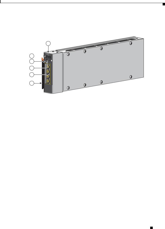
The Catalyst Switch Module 3110G and 3110X include the 10/100/1000 Ethernet ports or the 10-Gigabit Ethernet module slot, console port, StackWise Plus ports, release latch, and the switch module LEDs shown in Figure 1-1 and described on the following pages.
Figure 1-1 Catalyst Switch Module 3110G and 3110X
9
8
7
6
5
|
1 |
|
|
2 |
|
C |
|
|
|
|
|
|
|
|
C |
|
|
|
|
|
O |
|
|
L M |
|
|
N |
|
|
EO |
! |
|
S |
|
|
D |
|
L M |
|
|
|
|
|
O |
|
|
|
|
M |
M |
EO |
! |
|
|
B |
D |
|
||
|
R |
S |
E |
M |
|
|
T |
|
M |
||
|
|
|
B |
||
|
|
LNK |
|
R |
S |
|
|
|
|
T |
|
|
|
15 |
|
|
|
|
|
ACT |
|
X2 |
|
|
|
LNK |
|
|
|
|
|
|
|
|
|
|
|
16 |
|
|
|
|
|
ACT |
|
|
|
|
|
LNK |
|
|
|
|
|
17 |
|
|
|
|
|
ACT |
|
|
|
|
|
LNK |
|
|
|
|
|
18 |
|
|
|
|
|
ACT |
|
|
|
1 |
|
2 |
|
|
|
|
|
|
|
|
|
|
|
|
1 |
STACK |
2 |
|
|
|
|
4 3
201895
1 |
Catalyst Switch Module 3110G |
6 |
10/100/1000 Ethernet ports |
|
|
|
|
2 |
Catalyst Switch Module 3110X |
7 |
Switch module LEDs |
|
|
|
|
3 |
10-Gigabit Ethernet module slot1 |
8 |
Mode button |
4 |
StackWise Plus ports |
9 |
Console port |
|
|
|
|
5 |
Release latch |
|
|
|
|
|
|
1. For use with Cisco X2 transceiver modules.
Catalyst Switch Module 3110G, 3110X, and 3012 for IBM BladeCenter Hardware Installation Guide
1-2 |
OL-12192-01 |
|
|
Chapter 1 Product Overview
Hardware Features
The Catalyst Switch Module 3012 includes the 10/100/1000 Ethernet ports, console port, release latch, and the switch module LEDs shown in Figure 1-2 and described on the following pages.
Figure 1-2 Catalyst Switch Module 3012
1
C 2 
L M EO
3
|
LNK |
4 |
15 |
ACT |
|
|
LNK |
|
16 |
5 |
ACT |
LNK |
|
|
17 |
|
ACT |
6 |
LNK |
18 |
|
ACT |
270430
1 |
Catalyst Switch Module 3012 |
4 |
Switch module LEDs |
|
|
|
|
2 |
Console port |
5 |
10/100/1000 Ethernet ports |
|
|
|
|
3 |
Mode button |
6 |
Release latch |
|
|
|
|
10/100/1000 Ethernet Ports
The Catalyst Switch Module 3110G and 3012 10/100/1000 Ethernet ports use standard RJ-45 connectors with Ethernet pinouts. The maximum cable length is 328 feet (100 meters). The 100BASE-TX and 1000BASE-T traffic requires Category 5, Category 5e, or Category 6 unshielded twisted pair (UTP) cable. The 10BASE-T traffic can use Category 3 or Category 4 UTP cable.
For information about the 10/100/1000 Ethernet port connections and specifications, see the “Connecting Devices to the Ethernet Ports” section on page 2-13 and Appendix B, “Connector and Cable Specifications.”
Catalyst Switch Module 3110G, 3110X, and 3012 for IBM BladeCenter Hardware Installation Guide
|
OL-12192-01 |
1-3 |
|
|
|

Chapter 1 Product Overview
Hardware Features
10-Gigabit Ethernet Module Slot
The Catalyst Switch Module 3110X 10-Gigabit Ethernet module slot is used for an uplink connection to other switches and routers. The module slot operates in full-duplex mode and uses the hot-swappable Cisco X2 transceiver modules.
The X2 transceiver modules have a dual SC/PC connector (-SR, -LX4) or an Infiniband 4x connector (-CX4) for connections to multimode fiber (MMF), single-mode fiber (SMF), or 4x Infiniband cable.
These are the supported Cisco X2 transceiver modules:
•X2-10GB-SR
•X2-10GB-CX4
•X2-10GB-LX4
For information about installing a transceiver module, see the “Installing Devices in the 10-Gigabit Ethernet Slot” section on page 2-11. For cable specifications, see Appendix B, “Connector and Cable Specifications.”
Port Numbering
Table 1-2 describes the switch module port numbering.
Table 1-2 |
Switch Module Port Numbering |
|
|
|
|
Port |
|
Description |
|
|
|
Ports 1 to 141 |
|
Internal Gigabit Ethernet 1000BASE-X downlink ports that connect to |
|
|
the blade enclosure. |
|
|
|
Ports 15 to 18 (Catalyst Switch |
External 10/100/1000BASE-T copper Gigabit Ethernet uplink ports. |
|
Module 3110G and 3012) |
|
|
|
|
|
Port 1 (X2) (Catalyst Switch |
External 10-Gigabit Ethernet module slot. |
|
Module 3110X) |
|
|
|
|
|
1.The number of internal ports is determined by the blade enclosure model. See the blade enclosure documentation for more information about internal port numbering.
Internal 100BASE-T Ethernet Management Port
The internal Ethernet management port (Fa0) is used only for switch module management traffic, not for data traffic. It is connected to the IBM advanced Management Module (aMM) through the blade enclosure backplane connector. Traffic to and from this port is isolated from the switch module ports. This port only supports autonegotiation with 100 Mb/s and full-duplex mode.
Catalyst Switch Module 3110G, 3110X, and 3012 for IBM BladeCenter Hardware Installation Guide
1-4 |
OL-12192-01 |
|
|

Chapter 1 Product Overview
Hardware Features
Switch Module LEDs
You can use the switch module LEDs to monitor switch module activity. Figure 1-3 shows the switch module LEDs and the Mode button that you use to activate the different modes.
Figure 1-3 Switch Module LEDs and Mode Button
1 |
2 |
3 |
|
4 |
5 |
8 |
9 |
10 |
11 12 |
|
|
|
|
C |
|
|
|
|
|
C |
|
|
|
|
|
O |
|
|
|
|
|
O |
|
|
|
|
|
N |
|
|
|
|
|
N |
|
|
|
|
|
S |
|
|
|
|
|
S |
|
|
|
|
|
O |
|
|
|
|
|
O |
|
|
|
|
|
L |
|
|
|
|
|
L |
|
|
|
|
|
E M |
|
|
|
|
|
E M |
|
|
|
|
|
O |
|
|
|
|
|
O |
|
|
|
|
|
|
M |
|
|
|
|
|
M |
|
|
|
|
|
B |
|
S |
|
|
|
B |
S |
|
|
|
|
R |
|
T |
|
|
|
R |
T |
|
|
|
|
|
|
LNK |
6 |
|
|
|
|
|
|
|
|
|
|
|
|
|
|
|
|
|
|
|
|
|
|
15 |
|
|
|
|
|
13 |
|
|
|
|
|
|
|
|
X2 |
|
|
|
|
|
|
|
|
ACT |
7 |
|
|
|
|
|
|
|
|
|
|
|
|
|
|
|
||
|
|
|
|
|
|
|
|
|
|
|
|
|
|
|
|
|
LNK |
|
|
|
|
|
|
|
|
|
|
|
16 |
|
|
|
|
|
|
|
|
|
|
|
ACT |
|
|
|
|
|
|
|
|
|
|
|
LNK |
|
|
|
|
|
|
|
|
|
|
|
17 |
|
|
|
|
|
|
|
|
|
|
|
ACT |
|
|
|
|
|
|
|
|
|
|
|
LNK |
|
|
|
|
|
|
|
|
|
|
|
18 |
|
|
|
|
|
|
|
|
|
|
|
ACT |
|
|
|
|
|
|
|
|
1 |
STACK |
|
2 |
|
|
1 |
STACK |
2 |
201896 |
|
|
|
|
|
|
||||||
|
1 |
Stack member LED |
8 |
Stack member LED |
||||
|
|
|
(Catalyst Switch Module 3110G) |
|
|
|
|
|
|
|
|
|
|
||||
2 |
Mode button |
9 |
Mode button |
|||||
|
|
|
|
|
||||
3 |
Fault/stack mode LED |
10 |
Fault/stack mode LED |
|||||
|
|
|
(Catalyst Switch Module 3110G) |
|
|
|
|
|
|
|
|
Fault LED |
|
|
|
|
|
|
|
|
(Catalyst Switch Module 3012) |
|
|
|
|
|
|
|
|
|
|
||||
4 |
System power LED |
11 |
System power LED |
|||||
|
|
|
|
|
||||
5 |
Stack master LED |
12 |
Stack master LED |
|||||
|
|
|
(Catalyst Switch Module 3110G) |
|
|
|
|
|
|
|
|
|
|
||||
6 |
Port link LED |
13 |
X2 port status LEDs |
|||||
|
|
|
|
|
|
|
|
|
7 |
Port activity LED |
|
|
|
|
|
||
|
|
|
|
|
|
|
|
|
|
|
|
Catalyst Switch Module 3110G, 3110X, and 3012 for IBM BladeCenter Hardware Installation Guide |
|
|
|||
|
|
|
|
|||||
|
OL-12192-01 |
|
|
|
|
1-5 |
|
|
|
|
|
|
|
|
|||

Chapter 1 Product Overview
Hardware Features
Mode Button
The fault/stack or stack member LEDs are selected by using the Mode button. If the mode LED for a particular mode is solid green, that mode is currently selected, and the other mode LEDs are off (only Catalyst Switch Module 3110G and 3110X).
To select or change a mode, use a small pointed object to press the Mode button until the desired mode is selected.
System Power LED
The system power LED shows whether the system is receiving power and is functioning properly. Table 1-3 lists the LED colors and their meanings.
Table 1-3 |
System LED |
|
|
|
|
Color |
|
System Status |
|
|
|
Off |
|
Switch module is not powered on. |
|
|
|
Green |
|
Switch module is operating normally. |
|
|
|
Amber |
|
Switch module is receiving power but is not functioning properly. |
|
|
|
Blinking green |
|
Switch module is running the power-on self-test (POST). |
|
|
|
Stack Master LED
The stack master LED shows the stack master status. Table 1-4 lists the LED colors and their meanings (only Catalyst Switch Module 3110G and 3110X).
Table 1-4 |
Stack Master LED |
|
|
|
|
Color |
|
Description |
|
|
|
Off |
|
Switch module is not the stack master. |
|
|
|
Green |
|
Switch module is the stack master or a standalone switch. |
|
|
|
Amber |
|
An error occurred during stack master election, or another type of |
|
|
stack error occurred. |
|
|
|
Catalyst Switch Module 3110G, 3110X, and 3012 for IBM BladeCenter Hardware Installation Guide
1-6 |
OL-12192-01 |
|
|

Chapter 1 Product Overview
Hardware Features
Fault/Stack Mode LED
The fault/stack mode LED shows either a fault condition or the switch stack status, depending on the Mode button selection. When the switch module is not stacked and there is no fault, the LED is off. If the switch module is stacked and the stack mode LED is selected, the stack member LED is active.
Table 1-5 lists the LED colors and their meanings (only Catalyst Switch Module 3110G and 3110X).
Table 1-5 |
Fault/Stack Mode LED |
|
|
|
|
Color |
Fault Mode Description |
Stack Mode Description |
|
|
|
Off |
No switch module faults. |
Stack mode is not selected. |
|
|
|
Green |
— |
Switch stack mode is selected. When this LED is |
|
|
green, the stack member LED displays the stack |
|
|
membership number, and the port LEDs display link |
|
|
status. |
|
|
|
Amber |
Switch module fault |
— |
|
detected. |
|
|
|
|
Fault LED
The fault LED shows the switch module fault condition. Table 1-6 lists the LED colors and their meanings (only Catalyst Switch Module 3012).
Table 1-6 |
Fault LED |
|
|
|
|
Color |
|
Fault Mode Description |
|
|
|
Off |
|
No switch module faults. |
|
|
|
Amber |
|
Switch module fault detected. |
|
|
|
Stack Member LED
The stack member LED is active when the switch module is stacked and you select by using the Mode button. The stack member LED blinks the number of times equal to the switch stack membership number. Table 1-7 lists the LED colors and their meanings (only Catalyst Switch Module 3110G and 3110X).
Table 1-7 |
Fault/Stack Mode LED |
|
|
|
|
Color |
|
Description |
|
|
|
Off |
|
Stack mode is not selected, or the switch module is not stacked. |
|
|
|
Blinking green |
|
Stack member number. |
|
|
|
Catalyst Switch Module 3110G, 3110X, and 3012 for IBM BladeCenter Hardware Installation Guide
|
OL-12192-01 |
1-7 |
|
|
|

Chapter 1 Product Overview
Hardware Features
Port LEDs
The Catalyst Switch Module 3110G and 3012 port LEDs show interface activity and link status. Table 1-8 lists the LED colors and their meanings.
Table 1-8 |
Catalyst Switch Module 3110G and 3012 Port LEDs |
||
|
|
|
|
Color |
|
Activity LED Description |
Link Status LED Description |
|
|
|
|
Off |
|
No activity. |
No link, or port was administratively |
|
|
|
shut down. |
|
|
|
|
Green |
|
— |
Link present, or the port might be |
|
|
|
blocked by Spanning Tree Protocol |
|
|
|
(STP) and is not forwarding data. |
|
|
|
|
Blinking green |
|
Activity. Port is sending or receiving |
— |
|
|
data. |
|
|
|
|
|
When stack mode is selected on a Catalyst Switch Module 3110G, port 4 activity and link LEDs show the status for StackWise Plus ports 1 and 2, respectively. The other port LEDs are off. Table 1-9 lists the LED colors and their meanings.
Table 1-9 |
Catalyst Switch Module 3110G Port LEDs with Stack Mode Selected |
||
|
|
|
|
Color |
|
Activity LED Description |
Link Status LED Description |
|
|
|
|
Off |
|
No link. |
No link. |
|
|
|
|
Green |
|
Switch stack link is active. |
Switch stack link is active. |
|
|
|
|
The Catalyst Switch Module 3110X port status LEDs show interface activity and link status. (The LEDs combine to display status when an X2 transceiver is inserted.) Table 1-10 lists the LED colors and their meanings.
Table 1-10 |
Catalyst Switch Module 3110X Port LEDs |
|
|
|
|
Color |
|
LED Description |
|
|
|
Off |
|
No link, or port was administratively shut down. |
|
|
|
Green |
|
Link present. |
|
|
|
Blinking green |
|
Activity. Port is sending or receiving data. |
|
|
|
Amber |
|
Port is blocked by STP and is not forwarding data, or port was |
|
|
administratively shut down. |
|
|
|
Alternating |
|
Link fault. |
green-amber |
|
|
|
|
|
Catalyst Switch Module 3110G, 3110X, and 3012 for IBM BladeCenter Hardware Installation Guide
1-8 |
OL-12192-01 |
|
|

Chapter 1 Product Overview
Management Options
When stack mode is selected on a Catalyst Switch Module 3110X, the two port status LEDs show the status for StackWise Plus ports 1 and 2, respectively. Table 1-11 lists the LED colors and their meanings.
Table 1-11 |
Catalyst Switch Module 3110X Port Status LEDs with Stack Mode Selected |
|
|
|
|
Color |
|
Port Status LED Description |
|
|
|
Off |
|
No link. |
|
|
|
Green |
|
Switch stack link is active. |
|
|
|
StackWise Plus Ports
The switch module ships with a 1-meter StackWise Plus cable that you can use to connect the StackWise Plus ports (only Catalyst Switch Module 3110G and 3110X).
Caution Use only approved cables and connect only to Catalyst Switch Module 3110G and 3110X. Equipment might be damaged if connected to nonapproved Cisco cables or equipment.
You can order these StackWise Plus cables from your supplier:
•CAB-STK-E-0.5M= (0.5-meter cable)
•CAB-STK-E-1M= (1-meter cable)
•CAB-STK-E-3M= (3-meter cable)
Console Port
You can connect the switch module to a host such as a PC, workstation, or a terminal server through the console port (shown in Figure 1-1). Use the supplied USB-to-DB-9 cable to connect the switch module to a host.
For more information about the console port, see the switch module getting started guide, the software configuration guide, and the command reference on Cisco.com.
Management Options
The switch module offers several management options:
•Cisco IOS CLI
The switch module command-line interface (CLI) is based on Cisco IOS software and is enhanced to support desktop-switching features. You can fully configure and monitor the switch module and switch stack members from the CLI. You can access the CLI by connecting your management station directly to the switch module console port or by using Telnet from a remote management station.
See the switch module getting started guide, the software configuration guide, and the command reference on Cisco.com for more information.
•BladeCenter Advanced Management Module
For standalone switch modules, you can use the aMM to configure the switch module. See the IBM BladeCenter Advanced Management Module User’s Guide for more information. For stacked switches, use the CLI to configure and manage the switch stack.
Catalyst Switch Module 3110G, 3110X, and 3012 for IBM BladeCenter Hardware Installation Guide
|
OL-12192-01 |
1-9 |
|
|
|
Loading...