


102059

CISCO CONFIDENTIAL - Draft 1
Corporate Headquarters
Cisco Systems, Inc.
170 West Tasman Drive
San Jose, CA 95134-1706
USA
http://www.cisco.com
Tel: 408 526-4000
800 553-NETS (6387)
Fax: 408 526-4100
Cisco Aironet 1250AG Series Access Point
Hardware Installation Guide
June 2006
Text Part Number: OL-8247-01

CISCO CONFIDENTIAL - Draft 1
THE SPECIFICATIONS AND INFORMATION REGARDING THE PRODUCTS IN THIS MANUAL ARE SUBJECT TO CHANGE WITHOUT NOTICE. ALL
STATEMENTS, INFORMATION, AND RECOMMENDATIONS IN THIS MANUAL ARE BELIEVED TO BE ACCURATE BUT ARE PRESENTED WITHOUT
WARRANTY OF ANY KIND, EXPRESS OR IMPLIED. USERS MUST TAKE FULL RESPONSIBILITY FOR THEIR APPLICATION OF ANY PRODUCTS.
THE SOFTWARE LICENSE AND LIMITED WARRANTY FOR THE ACCOMPANYING PRODUCT ARE SET FORTH IN THE INFORMATION PACKET THAT
SHIPPED WITH THE PRODUCT AND ARE INCORPORATED HEREIN BY THIS REFERENCE. IF YOU ARE UNABLE TO LOCATE THE SOFTWARE LICENSE
OR LIMITED WARRANTY, CONTACT YOUR CISCO REPRESENTATIVE FOR A COPY.
The following information is for FCC compliance of Class A devices: This equipment has been tested and found to comply with the limits for a Class A digital device, pursuant
to part 15 of the FCC rules. These limits are designed to provide reasonable protection against harmful interference when the equipment is operated in a commercial
environment. This equipment generates, uses, and can radiate radio-frequency energy and, if not installed and used in accordance with the instruction manual, may cause
harmful interference to radio communications. Operation of this equipment in a residential area is likely to cause harmful interference, in which case users will be required
to correct the interference at their own expense.
The following information is for FCC compliance of Class B devices: The equipment described in this manual generates and may radiate radio-frequency energy. If it is not
installed in accordance with Cisco’s installation instructions, it may cause interference with radio and television reception. This equipment has been tested and found to
comply with the limits for a Class B digital device in accordance with the specifications in part 15 of the FCC rules. These specifications are designed to provide reasonable
protection against such interference in a residential installation. However, there is no guarantee that interference will not occur in a particular installation.
Modifying the equipment without Cisco’s written authorization may result in the equipment no longer complying with FCC requirements for Class A or Class B digital
devices. In that event, your right to use the equipment may be limited by FCC regulations, and you may be required to correct any interference to radio or television
communications at your own expense.
You can determine whether your equipment is causing interference by turning it off. If the interference stops, it was probably caused by the Cisco equipment or one of its
peripheral devices. If the equipment causes interference to radio or television reception, try to correct the interference by using one or more of the following measures:
• Turn the television or radio antenna until the interference stops.
• Move the equipment to one side or the other of the television or radio.
• Move the equipment farther away from the television or radio.
• Plug the equipment into an outlet that is on a different circuit from the television or radio. (That is, make certain the equipment and the television or radio are on circuits
controlled by different circuit breakers or fuses.)
Modifications to this product not authorized by Cisco Systems, Inc. could void the FCC approval and negate your authority to operate the product.
The Cisco implementation of TCP header compression is an adaptation of a program developed by the University of California, Berkeley (UCB) as part of UCB’s public
domain version of the UNIX operating system. All rights reserved. Copyright © 1981, Regents of the University of California.
NOTWITHSTANDING ANY OTHER WARRANTY HEREIN, ALL DOCUMENT FILES AND SOFTWARE OF THESE SUPPLIERS ARE PROVIDED “AS IS” WITH
ALL FAULTS. CISCO AND THE ABOVE-NAMED SUPPLIERS DISCLAIM ALL WARRANTIES, EXPRESSED OR IMPLIED, INCLUDING, WITHOUT
LIMITATION, THOSE OF MERCHANTABILITY, FITNESS FOR A PARTICULAR PURPOSE AND NONINFRINGEMENT OR ARISING FROM A COURSE OF
DEALING, USAGE, OR TRADE PRACTICE.
IN NO EVENT SHALL CISCO OR ITS SUPPLIERS BE LIABLE FOR ANY INDIRECT, SPECIAL, CONSEQUENTIAL, OR INCIDENTAL DAMAGES, INCLUDING,
WITHOUT LIMITATION, LOST PROFITS OR LOSS OR DAMAGE TO DATA ARISING OUT OF THE USE OR INABILITY TO USE THIS MANUAL, EVEN IF CISCO
OR ITS SUPPLIERS HAVE BEEN ADVISED OF THE POSSIBILITY OF SUCH DAMAGES.
Cisco Aironet 1250AG Series Access Point Hardware Installation Guide
© 2006 Cisco Systems, Inc. All rights reserved.
CCSP, CCVP, the Cisco Square Bridge logo, Follow Me Browsing, and StackWise are trademarks of Cisco Systems, Inc.; Changing the Way We Work, Live, Play, and Learn, and
iQuick Study are service marks of Cisco Systems, Inc.; and Access Registrar, Aironet, BPX, Catalyst, CCDA, CCDP, CCIE, CCIP, CCNA, CCNP, Cisco, the Cisco Certified
Internetwork Expert logo, Cisco IOS, Cisco Press, Cisco Systems, Cisco Systems Capital, the Cisco Systems logo, Cisco Unity, Enterprise/Solver, EtherChannel, EtherFast,
EtherSwitch, Fast Step, FormShare, GigaDrive, GigaStack, HomeLink, Internet Quotient, IOS, IP/TV, iQ Expertise, the iQ logo, iQ Net Readiness Scorecard, LightStream,
Linksys, MeetingPlace, MGX, the Networkers logo, Networking Academy, Network Registrar, Pack e t, PIX, Post-Routing, Pre-Routing, ProConnect, RateMUX, ScriptShare,
SlideCast, SMARTnet, The Fastest Way to Increase Your Internet Quotient, and TransPath are registered trademarks of Cisco Systems, Inc. and/or its affiliates in the United States
and certain other countries.
All other trademarks mentioned in this document or Website are the property of their respective owners. The use of the word partner does not imply a partnership relationship
between Cisco and any other company. (0601R)

CHA P TER
CISCO CONFIDENTIAL - Draft 1
1-1
Cisco Aironet 1250AG Series Access Point Hardware Installation Guide
OL-8247-01
1
Overview
Cisco Aironet 1250AG Series Access Points combine mobility, flexibility, and modularity with the
enterprise-class features required by networking professionals. With a management system based on
Cisco IOS software software, the 1250AG series access point is a Wi-Fi certified, wireless LAN
transceiver.
The access point supports two radio modules: a 2.4-GHz radio (IEEE 802.11b/g) and a 5-GHz radio
(IEEE 802.11a). The modular design enables support for a future IEEE802.11n radio module once the
standard is ratified. This modularity helps customers future proof their access point investments.
You can configure the radios separately, using different settings on each. The access point connects
wireless and wired networks or is the center point of a stand-alone wireless network. In large
installations, wireless users within radio range of an access point can roam throughout a facility while
maintaining seamless, uninterrupted access to the network.
You can configure and monitor the access point using the command-line interface (CLI), the
browser-based management system, Simple Network Management Protocol (SNMP), or Cisco
Structured Wireless-Aware Network (SWAN).
This chapter provides information on the following topics:
• Hardware Features, page 1-2
• Network Configuration Examples, page 1-7

CISCO CONFIDENTIAL - Draft 1
1-2
Cisco Aironet 1250AG Series Access Point Hardware Installation Guide
OL-8247-01
Chapter 1 Overview
Hardware Features
Hardware Features
Key hardware features of the access point include:
• Dual-radio operation with radio modules (see page 1-4)
• Ethernet port (see page 1-5)
• Console port (see page 1-5)
• LEDs, (see page 1-5)
• Multiple power sources (see page 1-5)
• UL 2043 certification (see page 1-6)
• Anti-theft features (see page 1-6)
Refer to Appendix C, “Access Point Specifications,” for a list of access point specifications.
Figure 1-2 shows the access point with two radio modules.
Figure 1-1 Access Point with 802.11b/g and 802.11a Radio Modules

CISCO CONFIDENTIAL - Draft 1
1-3
Cisco Aironet 1250AG Series Access Point Hardware Installation Guide
OL-8247-01
Chapter 1 Overview
Hardware Features
Figure 1-2 illustrates the 2.4-GHz radio module.
Figure 1-2 2.4 GHz Radio Module
Figure 1-3 illustrates the 5-GHz radio module.
Figure 1-3 5-GHz Radio Module
1 2.4-GHz antenna connector (left) 3
2 2.4-GHz antenna connector (right/primary) 5
1 5-GHz antenna connector (left) 3
2 5-GHz antenna connector (right/primary)
CISCO CONFIDENTIAL - Draft 1
1-4
Cisco Aironet 1250AG Series Access Point Hardware Installation Guide
OL-8247-01
Chapter 1 Overview
Hardware Features
Single or Dual-Radio Operation
The access point supports single or simultaneous dual radio operation using 2.4-GHz 802.11b/g radio
and 5-GHz 802.11a radio modules. Each radio uses dual-diversity integrated antennas. A blank module
is supported for single radio access point configurations.
The access point supports upgrading of a radio module with a 802.11n radio module (future availability).
The 802.11n radio module will be available when the standard is ratified.
The 5-GHz radio incorporates an Unlicensed National Information Infrastructure (UNII) radio
transceiver operating in the UNII 5-GHz frequency bands. The 802.11g radio is called Radio0 and the
802.11a radio is called Radio1.
Note In Cisco IOS Release 12.3(8)JA and later, the access point radios are disabled by default, and there is no
default SSID. You must create an SSID and enable the radios before the access point allows wireless
associations from other devices.
Antennas Supported
Table 1-1 lists the supported access point antennas.
Caution The access point, the antennas, and the power source (power injector or power module) must be located
in an indoor environment.
Table 1-1 Supported Antennas
2.4-GHz Antennas
Gain
(dBi) 5-GHz Antennas
Gain
(dBi)
AIR-ANT5959 diversity ceiling omnidirectional 2 AIR-ANT5135D-R articulated omnidirectional 3.5
AIR-ANT4941 articulated dipole 2.2 AIR-ANT5145V-R diversityceiling omnidirectional 4.5
AIR-ANT1728 ceiling omnidirectional 5.2 AIR-ANT5160V-R omnidirectional 6
AIR-ANT2506 mast mount omnidirectional 5.2 AIR-ANT5170P-R diversity wall patch directional 7
AIR-ANT3213 diversity pillar omnidirectional 5.2 AIR-ANT5195P-R wall patch directional 9.5
AIR-ANT1729 wall patch directional 6
AIR-ANT2460P-R patch directional 6
AIR-ANT2465P-R diversity patch directional 6.5
AIR-ANT2012 diversity patch directional 6.5
AIR-ANT3549 patch directional 9
AIR-ANT2490P-R patch directional 9
AIR-ANT2410Y-R
yagi directional 10

CISCO CONFIDENTIAL - Draft 1
1-5
Cisco Aironet 1250AG Series Access Point Hardware Installation Guide
OL-8247-01
Chapter 1 Overview
Hardware Features
Ethernet Port
The auto-sensing Ethernet port (see Figure TBD ) accepts an RJ-45 connector, linking the access point
to your 10BASE-T, 100BASE-T, or 1000BASE-T Ethernet LAN. The access point can receive power
through the Ethernet cable from a power injector, switch, or power patch panel. The Ethernet MAC
address is printed on the label on the back of the access point (refer to the “Locating the Product Serial
Number” section on page -viii).
Console Port
The serial console port provides access to the access point’s command-line interface (CLI) using a
terminal emulator program. The port is located on the end of the unit (see Figure 1-2). Use an RJ-45 to
DB-9 serial cable to connect your computer’s COM port to the access point’s serial console port. (Refer
to Appendix E, “Console Cable Pinouts,” for a description of the console port pinouts.) Assign the
following port settings to a terminal emulator to open the management system pages: 9600 baud, 8 data
bits, no parity, 1 stop bit, and no flow control.
Note After completing your configuration changes, you must remove the serial cable from the access point.
LEDs
The access point has three LEDs (see Figure 1-2) to indicate Ethernet activity, radio activity, and status
indications (refer to the “Checking the Access Point LEDs” section on page 6-2 for additional
information).
• The Status LED provides general operating status and error indications.
• The Ethernet LED signals Ethernet traffic on the wired Ethernet LAN and provides Ethernet error
indications.
• The Radio LED signals that wireless packets are being transmitted or received over the radio
interface and provides error indications.
Power Sources
The access point can receive power from an external power module or from inline power using the
Ethernet cable. The access point supports the IEEE 802.3af inline power standard and Cisco CDP Power
Negotiation. Using inline power, you do not need to run a power cord to the access point because power
is supplied over the Ethernet cable.
Warning
This product must be connected to a Power over Ethernet (PoE) IEEE 802.3af compliant power source
or an IEC60950 compliant limited power source.
Statement 353
The access point supports the following power sources:
• Power module
• Inline power:
–
Cisco Aironet 1250 Series Power Injector ( (AIR-PWRINJ3 or AIR-PWRINJ-FIB)
–
An inline power capable switch, such as the Cisco Catalyst 3550 PWR XL, 3560-48PS,
3570-48PS, 4500 with 802.3AF PoE module, or the 6500 with 802.3AF PoE module

CISCO CONFIDENTIAL - Draft 1
1-6
Cisco Aironet 1250AG Series Access Point Hardware Installation Guide
OL-8247-01
Chapter 1 Overview
Hardware Features
–
Other inline power switches supporting the IEEE 802.3af inline power standard
Note Some switches and patch panels might not provide enough power to operate the access point with both
2.4-GHz and 5-GHz radios. At power-up, if the access point is unable to determine that the power source
can supply sufficient power, the access point automatically deactivates both radios to prevent an
over-current condition. The access point also activates a Status LED low power error indication and
creates an error log entry (refer to the “Checking the Access Point LEDs” section on page 6-2 and the
“Low Power Condition” section on page 6-5).
UL 2043 Certification
The access point has adequate fire resistance and low smoke-producing characteristics suitable for
operation in a building's environmental air space, such as above suspended ceilings, in accordance with
Section 300-22(c) of the NEC, and with Sections 2-128, 12-010(3) and 12-100 of the Canadian
Electrical Code, Part 1, C22.1.
Caution Only the fiber-optic power injector (AIR-PWRINJ-FIB) has been tested to UL 2043 for operation in a
building’s environmental air space; the AIR-PWRINJ3 power injector and the power module are not
tested to UL 2043 and should not be placed in a building’s environmental air space, such as above
suspended ceilings.
Anti-Theft Features
TBD
CISCO CONFIDENTIAL - Draft 1
1-7
Cisco Aironet 1250AG Series Access Point Hardware Installation Guide
OL-8247-01
Chapter 1 Overview
Network Configuration Examples
Network Configuration Examples
This section describes the access point’s role in three common wireless network configurations. The
access point’s default configuration is as a root unit connected to a wired LAN or as the central unit in
an all-wireless network. The repeater role requires a specific configuration.
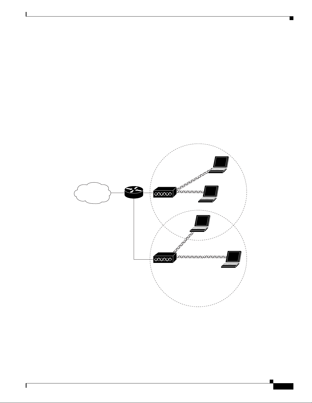
Root Unit on a Wired LAN
An access point connected directly to a wired LAN provides a connection point for wireless users. If
more than one access point is connected to the LAN, users can roam from one area of a facility to another
without losing their connection to the network. Figure 1-4 shows access points acting as root units on a
wired LAN.
Figure 1-4 Access Points as Root Units on a Wired LAN
Access point
Access point
135445
CISCO CONFIDENTIAL - Draft 1
1-8
Cisco Aironet 1250AG Series Access Point Hardware Installation Guide
OL-8247-01
Chapter 1 Overview
Network Configuration Examples
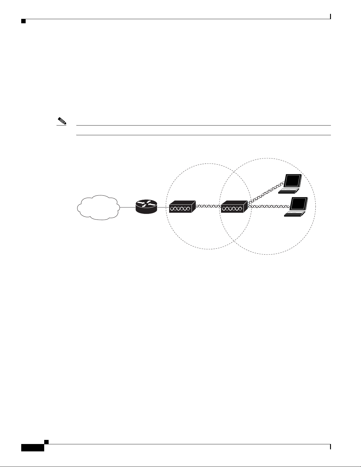
Repeater Unit that Extends Wireless Range
An access point can be configured as a stand-alone repeater to extend the range of your infrastructure or
to overcome an obstacle that blocks radio communication. The repeater forwards traffic between
wireless users and the wired LAN by sending packets to either another repeater or to an access point
connected to the wired LAN. The data is sent through the route that provides the best performance for
the client. Figure 1-5 shows an access point acting as a repeater. Consult the Cisco IOS Software
Configuration Guide for Cisco Aironet Access Points for instructions on setting up an access point as a
repeater.
Note Non-Cisco client devices might have difficulty communicating with repeater access points.
Figure 1-5 Access Point as Repeater
Access point Repeater
135444
 Loading...