


C H A P T E R 2
Cards Specifications
This chapter contains specific information about cards for dense wavelength division multiplexing (DWDM) applications in the Cisco ONS 15454.
Note The terms "Unidirectional Path Switched Ring" and "UPSR" may appear in Cisco literature. These terms do not refer to using Cisco ONS 15xxx products in a unidirectional path switched ring configuration. Rather, these terms, as well as "Path Protected Mesh Network" and "PPMN," refer generally to Cisco's path protection feature, which may be used in any topological network configuration. Cisco does not recommend using its path protection feature in any particular topological network configuration.
The following topics are covered in this chapter:
•2.1 Card Overview, page 2-1
•2.2 Card Specifications, page 2-12
2.1Card Overview
Redundant TCC2 and TCC2P cards are required to operate the Cisco ONS 15454. If you are using an ETSI (SDH) shelf assembly, the MIC-A/P and MIC-C/T/P front mount electrical connections (FMECs) are also required. The optional AIC-I card provides external alarms and controls (environmental alarms).
Each DWDM card is marked with a symbol that corresponds to a slot (or slots) on the ONS 15454 shelf assembly. These cards can only be installed into slots displaying the same symbols.
ONS 15454 DWDM cards are grouped into the following categories:
•Optical service channel OSC) cards provide bidirectional channels that connect all the ONS 15454 DWDM nodes and transport general-purpose information without affecting the client traffic.
ONS 15454 OSC cards include the Optical Service Channel Module (OSCM) and the Optical Service Channel and Combiner/Separator Module (OSC-CSM).
•Optical erbium-doped fiber amplifier (EDFA) cards are used in amplified DWDM nodes, including hub nodes, amplified OADM nodes, and line amplified nodes. Optical amplifier cards include the Optical Preamplifier (OPT-PRE) and Optical Booster (OPT-BST).
•Dispersion compensation units (DCUs) are installed in the ONS 15454 dispersion compensation shelf when optical preamplifier cards are installed in the DWDM node. Each DCU module can compensate a maximum of 65 km of single-mode fiber (SMF-28) span. DCUs can be cascaded to extend the compensation to 130 km.
Cisco ONS 15454 DWDM Engineering and Planning Guide, Release 7.x
|
July 2006 |
2-1 |
|
|
|

Chapter 2 Cards Specifications
2.1 Card Overview
•Multiplexer and demultiplexer cards multiplex and demultiplex DWDM optical channels. The cards consist of three main modules: an optical plug-in, a microprocessor, and a DC/DC converter. ONS 15454 multiplexer and demultiplexer cards include the 32-Channel Multiplexer (32MUX-O), the 32-Channel Demultiplexer (32DMX-O), the single-slot 32-Channel Demultiplexer (32DMX), and the 4-Channel Multiplexer/Demultiplexer (4MD-xx.x).
•Optical Add/Drop Multiplexer (OADM) cards are mainly divided into three groups: band OADM cards, channel OADM cards, and wavelength selective switch (WSS) cards. Band OADM cards add and drop one or four bands of adjacent channels; they include the 4-Band OADM (AD-4B-xx.x) and the 1-Band OADM (AD-1B-xx.x). Channel OADM cards add and drop one, two, or four adjacent channels; they include the 4-Channel OADM (AD-4C-xx.x), the 2-Channel OADM (AD-2C-xx.x) and the 1-Channel OADM (AD-1C-xx.x). The 32-Channel Wavelength Selective Switch (32WSS) card is used with the 32DMX to implement reconfigurable OADM (ROADM) functionality. These cards consist of three main modules: an optical plug-in, a microprocessor, and a DC/DC converter.
Table 2-1 to Table 2-4 show the band IDs and the add/drop channel IDs for the 4MD-xx.x, AD-2C-xx.x, AD-4C-xx.x, and AD-4B-xx.x cards.
Table 2-1 |
4MD-xx.x Channel Sets |
|
|
|
|
|
|
Band IDs |
|
Add/Drop Channel IDs |
Add/Drop Wavelengths (nm) |
|
|
|
|
Band 30.3 (A) |
|
30.3, 31.2, 31.9, 32.6 |
1530.33, 1531.12, 1531.90, |
|
|
|
1532.68 |
|
|
|
|
Band 34.2 (B) |
|
34.2, 35.0, 35.8, 36.6 |
1534.25, 1535.04, 1535.82, |
|
|
|
1536.61 |
|
|
|
|
Band 38.1 (C) |
|
38.1, 38.9, 39.7, 40.5 |
1538.19, 1538.98, 1539.77, |
|
|
|
1540.56 |
|
|
|
|
Band 42.1 (D) |
|
42.1, 42.9, 43.7, 44.5 |
1542.14, 1542.94, 1543.73, |
|
|
|
1544.53 |
|
|
|
|
Band 46.1 (E) |
|
46.1, 46.9, 47.7, 48.5 |
1546.12, 1546.92, 1547.72, |
|
|
|
1548.51 |
|
|
|
|
Band 50.1 (F) |
|
50.1, 50.9, 51.7, 52.5 |
1550.12, 1550.92, 1551.72, |
|
|
|
1552.52 |
|
|
|
|
Band 54.1 (G) |
|
54.1, 54.9, 55.7, 56.5 |
1554.13, 1554.94, 1555.75, |
|
|
|
1556.55 |
|
|
|
|
Band 58.1 (H) |
|
58.1, 58.9, 59.7, 60.6 |
1558.17, 1558.98, 1559.79, |
|
|
|
1560.61 |
|
|
|
|
Table 2-2 |
AD-2C-xx.x Channel Pairs |
|
|
|
|
|
|
Band IDs |
|
Add/Drop Channel IDs |
Add/Drop Wavelengths (nm) |
|
|
|
|
Band 30.3 (A) |
|
30.3, 31.2 and 31.9, 32.6 |
1530.33, 1531.12 and 1531.90, |
|
|
|
1532.68 |
|
|
|
|
Band 34.2 (B) |
|
34.2, 35.0, and 35.8, 36.6 |
1534.25, 1535.04 and 1535.82, |
|
|
|
1536.61 |
|
|
|
|
Band 38.1 (C) |
|
38.1, 38.9 and 39.7, 40.5 |
1538.19, 1538.98 and 1539.77, |
|
|
|
1540.56 |
|
|
|
|
Cisco ONS 15454 DWDM Engineering and Planning Guide, Release 7.x
2-2 |
July 2006 |
|
|

Chapter 2 Cards Specifications
|
|
|
|
|
2.1 Card Overview |
|
||||
|
|
Table 2-2 |
AD-2C-xx.x Channel Pairs (continued) |
|
|
|
|
|
|
|
|
|
|
|
|
|
|||||
|
|
Band IDs |
|
Add/Drop Channel IDs |
Add/Drop Wavelengths (nm) |
|||||
|
|
|
|
|
|
|||||
|
|
Band 42.1 (D) |
|
42.1, 42.9 and 43.7, 44.5 |
1542.14, 1542.94 and 1543.73, |
|||||
|
|
|
|
|
1544.53 |
|
|
|
|
|
|
|
|
|
|
|
|||||
|
|
Band 46.1 (E) |
|
46.1, 46.9 and 47.7, 48.5 |
1546.12, 1546.92 and 1547.72, |
|||||
|
|
|
|
|
1548.51 |
|
|
|
|
|
|
|
|
|
|
|
|||||
|
|
Band 50.1 (F) |
|
50.1, 50.9 and 51.7, 52.5 |
1550.12, 1550.92 and 1551.72, |
|||||
|
|
|
|
|
1552.52 |
|
|
|
|
|
|
|
|
|
|
|
|||||
|
|
Band 54.1 (G) |
|
54.1, 54.9 and 55.7, 56.5 |
1554.13, 1554.94 and 1555.75, |
|||||
|
|
|
|
|
1556.55 |
|
|
|
|
|
|
|
|
|
|
|
|||||
|
|
Band 58.1 (H) |
|
58.1, 58.9 and 59.7, 60.6 |
1558.17, 1558.98 and 1559.79, |
|||||
|
|
|
|
|
1560.61 |
|
|
|
|
|
|
|
|
|
|
|
|
|
|
|
|
|
|
Table 2-3 |
AD-4C-xx.x Channel Sets |
|
|
|
|
|
|
|
|
|
|
|
|
|
|||||
|
|
Band IDs |
|
Add/Drop Channel IDs |
Add/Drop Wavelengths (nm) |
|||||
|
|
|
|
|
|
|
|
|||
|
|
Band 30.3 (A) |
|
30.3, 31.2, 31.9, 32.6 |
1530.33, 1531.12, 1531.90, |
|
|
|||
|
|
|
|
|
1532.68 |
|
|
|
|
|
|
|
|
|
|
|
|
|
|||
|
|
Band 34.2 (B) |
|
34.2, 35.0, 35.8, 36.6 |
1534.25, 1535.04, 1535.82, |
|
|
|||
|
|
|
|
|
1536.61 |
|
|
|
|
|
|
|
|
|
|
|
|
|
|||
|
|
Band 38.1 (C) |
|
38.1, 38.9, 39.7, 40.5 |
1538.19, 1538.98, 1539.77, |
|
|
|||
|
|
|
|
|
1540.56 |
|
|
|
|
|
|
|
|
|
|
|
|
|
|||
|
|
Band 42.1 (D) |
|
42.1, 42.9, 43.7, 44.5 |
1542.14, 1542.94, 1543.73, |
|
|
|||
|
|
|
|
|
1544.53 |
|
|
|
|
|
|
|
|
|
|
|
|
|
|||
|
|
Band 46.1 (E) |
|
46.1, 46.9, 47.7, 48.5 |
1546.12, 1546.92, 1547.72, |
|
|
|||
|
|
|
|
|
1548.51 |
|
|
|
|
|
|
|
|
|
|
|
|
|
|||
|
|
Band 50.1 (F) |
|
50.1, 50.9, 51.7, 52.5 |
1550.12, 1550.92, 1551.72, |
|
|
|||
|
|
|
|
|
1552.52 |
|
|
|
|
|
|
|
|
|
|
|
|
|
|||
|
|
Band 54.1 (G) |
|
54.1, 54.9, 55.7, 56.5 |
1554.13, 1554.94, 1555.75, |
|
|
|||
|
|
|
|
|
1556.55 |
|
|
|
|
|
|
|
|
|
|
|
|
|
|||
|
|
Band 58.1 (H) |
|
58.1, 58.9, 59.7, 60.6 |
1558.17, 1558.98, 1559.79, |
|
|
|||
|
|
|
|
|
1560.61 |
|
|
|
|
|
|
|
|
|
|
|
|
|
|
|
|
|
|
Table 2-4 |
AD-4B-xx.x Channel Sets |
|
|
|
|
|
|
|
|
|
|
|
|
|
|||||
|
|
Band IDs |
|
Add/Drop Channel IDs |
Add/Drop Wavelengths (nm) |
|||||
|
|
|
|
|
|
|
|
|
|
|
|
|
Band 30.3 (A) |
|
B30.3 |
1530.33 |
|
|
|
|
|
|
|
|
|
|
|
|
|
|
|
|
|
|
Band 34.2 (B) |
|
B34.2 |
1534.25 |
|
|
|
|
|
|
|
|
|
|
|
|
|
|
|
|
|
|
Band 38.1 (C) |
|
B38.1 |
1538.19 |
|
|
|
|
|
|
|
|
|
|
|
|
|
|
|
|
|
|
Band 42.1 (D) |
|
B42.1 |
1542.14 |
|
|
|
|
|
|
|
|
|
|
|
|
|
|
|
|
|
|
Band 46.1 (E) |
|
B46.1 |
1546.12 |
|
|
|
|
|
|
|
|
|
|
|
|
|
|
|
|
|
|
Band 50.1 (F) |
|
B50.1 |
1550.12 |
|
|
|
|
|
|
|
|
|
|
|
|
|
|
||
|
|
|
|
Cisco ONS 15454 DWDM Engineering and Planning Guide, Release 7.x |
|
|
|
|
||
|
|
|
|
|||||||
|
July 2006 |
|
|
|
|
2-3 |
|
|
||
|
|
|
|
|
|
|||||

Chapter 2 Cards Specifications
2.1 Card Overview
Table 2-4 |
AD-4B-xx.x Channel Sets |
|
|
|
|
|
|
Band IDs |
|
Add/Drop Channel IDs |
Add/Drop Wavelengths (nm) |
|
|
|
|
Band 54.1 (G) |
|
B54.1 |
1554.13 |
|
|
|
|
Band 58.1 (H) |
|
B58.1 |
1558.17 |
|
|
|
|
•Transponder (TXP) and muxponder (MXP) cards convert the “gray” optical client interface signals into trunk signals that operate in the “colored” DWDM wavelength range. Transponding or muxponding is the process of converting the signals between the client and trunk wavelengths.
A muxponder generally handles several client signals. It aggregates, or multiplexes, lowerrate client signals together and sends them out over a higher-rate trunk port. Likewise, a muxponder demultiplexes optical signals coming in on a trunk and sends the signals out to individual client ports. A transponder converts a single client signal to a single trunk signal and converts a single incoming trunk signal to a single client signal.
All of the TXP and MXP cards perform optical-to-electrical-to-optical (OEO) conversion. As a result, they are not optically transparent cards. OEO conversion is necessary because the cards must operate on the signals passing through the cards.
However, the termination mode for all TXPs and MXPs can be configured as transparent (termination is performed at the electrical level). In a transparent termination, neither the Line nor the Section overhead is terminated. The cards can also be configured so that Line overhead, Section overhead, or both Line and Section overhead can be terminated.
Note When configured in the transparent termination mode, the MXP_2.5G_10G card does terminate some bytes by design.
Table 2-5 describes the Cisco ONS 15454 DWDM cards. Client-facing gray optical signals generally operate at shorter wavelengths, whereas DWDM colored optical signals are in the longer wavelength range (for example, 1490 nm = violet; 1510 nm = blue; 1530 nm = green; 1550 nm = yellow; 1570 nm = orange; 1590 nm = red; 1610 nm = brown). Some of the newer client-facing SFPs, however, operate in the colored region.
Cisco ONS 15454 DWDM Engineering and Planning Guide, Release 7.x
2-4 |
July 2006 |
|
|

Chapter 2 Cards Specifications
2.1 Card Overview
Table 2-5 |
Cisco ONS 15454 DWDM Cards |
|
|
|
|
|
|
Card |
|
Part Number |
Description |
|
|
|
|
Optical Service Channel Cards |
|
||
|
|
|
|
OSCM |
|
15454-OSCM= |
The OSCM card has one set of optical ports and one Ethernet port |
|
|
|
located on the faceplate. The card operates in Slots 8 and 10. |
|
|
|
An OSC is a bidirectional channel connecting all the nodes in a ring. |
|
|
|
The channel transports OSC overhead that is used to manage |
|
|
|
ONS 15454 DWDM networks. The OSC uses the 1510 nm |
|
|
|
wavelength and does not affect client traffic. The primary purpose of |
|
|
|
this channel is to carry clock synchronization and orderwire channel |
|
|
|
communications for the DWDM network. It also provides transparent |
|
|
|
links between each node in the network. The OSC is an OC-3 |
|
|
|
formatted signal. |
|
|
|
The OSCM is used in amplified nodes that include the OPT-BST |
|
|
|
booster amplifier. The OPT-BST includes the required OSC |
|
|
|
wavelength combiner and separator component. The OSCM cannot be |
|
|
|
used in nodes where you use OC-N cards, electrical cards, or |
|
|
|
cross-connect cards. The OSCM uses Slots 8 and 10 when the |
|
|
|
ONS 15454 is configured in a DWDM network. |
|
|
|
|
OSC-CSM |
|
15454-OSC-CSM= |
The OSC-CSM card has three sets of optical ports and one Ethernet |
|
|
|
port located on the faceplate. The card operates in Slots 1 to 6 and 12 |
|
|
|
to 17. |
|
|
|
The OSC-CSM is identical to the OSCM, but also contains a combiner |
|
|
|
and separator module in addition to the OSC module. |
|
|
|
The OSC-CSM is used in unamplified nodes. This means that the |
|
|
|
booster amplifier with the OSC wavelength combiner and separator is |
|
|
|
not required for OSC-CSM operation. The OSC-CSM can be installed |
|
|
|
in Slots 1 to 6 and 12 to 17 when the ONS 15454 is configured in a |
|
|
|
DWDM network. |
|
|
|
|
Optical Amplifiers |
|
||
|
|
|
|
OPT-PRE |
|
15454-OPT-PRE= |
The OPT-PRE card is designed to support 64 channels at 50 GHz |
|
|
|
channel spacing. The OPT-PRE is a C-band DWDM, two-stage EDFA |
|
|
|
with mid-amplifier loss (MAL) for allocation to a DCU. To control the |
|
|
|
gain tilt, the OPT-PRE is equipped with a built-in variable optical |
|
|
|
attenuator (VOA). The VOA can also be used to pad the DCU to a |
|
|
|
reference value. You can install the OPT-PRE in Slots 1 to 6 and 12 to |
|
|
|
17 when the ONS 15454 is configured in a DWDM network. |
|
|
|
|
OPT-BST |
|
15454-OPT-BST= |
The OPT-BST card is designed to support up to 64 channels at 50 GHz |
|
|
|
channel spacing. The OPT-BST is a C-band DWDM EDFA with OSC |
|
|
|
add-and-drop capability. When an ONS 15454 DWDM has an |
|
|
|
OPT-BST installed, it is only necessary to have the OSCM to process |
|
|
|
the OSC. The card has a maximum output power of 17 dBm. To |
|
|
|
control the gain tilt, the OPT-BST is equipped with a built-in VOA. |
|
|
|
You can install the OPT-BST in Slots 1 to 6 and 12 to 17 when the |
|
|
|
ONS 15454 is configured in a DWDM network. |
|
|
|
|
Cisco ONS 15454 DWDM Engineering and Planning Guide, Release 7.x
|
July 2006 |
2-5 |
|
|
|

Chapter 2 Cards Specifications
2.1 Card Overview
Table 2-5 |
Cisco ONS 15454 DWDM Cards (continued) |
||
|
|
|
|
Card |
|
Part Number |
Description |
|
|
|
|
OPT-BST-E |
|
15454-OPT-BST-E= |
The OPT-BST-E card is designed to support up to 64 channels at |
|
|
|
50 GHz channel spacing. It is a C-band DWDM EDFA with OSC |
|
|
|
add-and-drop capability. Its maximum output power is 21 dBm. To |
|
|
|
control the gain tilt, the OPT-BST-E is equipped with a built-in VOA. |
|
|
|
You can install the OPT-BST-E in Slots 1 to 6 and 12 to 17 when the |
|
|
|
ONS 15454 is configured in a DWDM network. |
|
|
|
|
OPT-BST-L |
|
15454-OPT-BST-L= |
The OPT-BST-L card is designed to support up to 64 channels at |
|
|
|
50 GHz channel spacing. It is an L-band DWDM EDFA with OSC |
|
|
|
add-and-drop capability. Its maximum output power is 17 dBm. To |
|
|
|
control the gain tilt, the OPT-BST-L is equipped with a built-in VOA. |
|
|
|
You can install the OPT-BST-L in Slots 1 to 6 and 12 to 17 when the |
|
|
|
ONS 15454 is configured in a DWDM network. |
|
|
|
|
OPT-AMP-L |
|
15454-OPT-AMP-L= |
The OPT-AMP-L card is designed to support 64 channels at 50 GHz |
|
|
|
channel spacing. The OPT-AMP-L is a L-band DWDM, two-stage |
|
|
|
EDFA with MAL for allocation to a DCU. Its maximum output power |
|
|
|
is 20 dBm. To control the gain tilt, the OPT-AMP-L is equipped with |
|
|
|
a built-in VOA. The VOA can also be used to pad the DCU to a |
|
|
|
reference value. OPT-AMP-L is a double-slot card. You can install the |
|
|
|
OPT-AMP-L in Slots 1-2, 3-4, 5-6, or in Slots 12-13, 14-15, or 16-17. |
|
|
|
|
Multiplexer and Demultiplexer Cards |
|
||
|
|
|
|
32MUX-O |
|
15454-32MUX-O= |
The 32MUX-O card multiplexes 32 100 GHz-spaced channels |
|
|
|
identified in the channel plan. The 32MUX-O card takes up two slots |
|
|
|
in an ONS 15454 DWDM and can be installed in Slots 1 to 5 and 12 |
|
|
|
to 16. |
|
|
|
|
32DMX-O |
|
15454-32DMX-O= |
The 32DMX-O card demultiplexes 32 100-GHz-spaced channels |
|
|
|
identified in the channel plan. The 32DMX-O takes up two slots in an |
|
|
|
ONS 15454 DWDM and can be installed in Slots 1 to 5 and 12 to 16. |
|
|
|
|
32DMX |
|
15454-32DMX= |
The 32DMX card is a single-slot optical demultiplexer. The card |
|
|
|
receives an aggregate optical signal on its COM RX port and |
|
|
|
demultiplexes it into to 32 100-GHz-spaced channels. The 32DMX |
|
|
|
card can be installed in Slots 1 to 6 and in Slots 12 to 17. |
|
|
|
|
32DMX-L |
|
15454-32DMX-L= |
The 32DMX-L card is a single-slot optical L-band demultiplexer. The |
|
|
|
card receives an aggregate optical signal on its COM RX port and |
|
|
|
demultiplexes it into to 32 100 GHz-spaced channels. The 32DMX |
|
|
|
card can be installed in Slots 1 to 6 and in Slots 12 to 17. |
|
|
|
|
4MD-xx.x |
|
15454-4MD-xx.x= |
The 4MD-xx.x card multiplexes and demultiplexes four |
|
|
|
100 GHz-spaced channels identified in the channel plan. The |
|
|
|
4MD-xx.x card is designed to be used with band OADMs (both |
|
|
|
AD-1B-xx.x and AD-4B-xx.x). There are eight versions of this card |
|
|
|
that correspond with the eight subbands specified in Table 2-1 on |
|
|
|
page 2-2. The 4MD-xx.x can be installed in Slots 1 to 6 and 12 to 17 |
|
|
|
when the ONS 15454 is configured in a DWDM network. |
|
|
|
|
Optical Add/Drop Multiplexer Cards |
|
||
|
|
|
|
Cisco ONS 15454 DWDM Engineering and Planning Guide, Release 7.x
2-6 |
July 2006 |
|
|

Chapter 2 Cards Specifications
2.1 Card Overview
Table 2-5 |
Cisco ONS 15454 DWDM Cards (continued) |
||||||||
|
|
|
|
|
|
||||
|
Card |
|
Part Number |
Description |
|||||
|
|
|
|
|
|
||||
|
AD-1C-xx.x |
|
15454-AD-1C-xx.x= |
The AD-1C-xx.x card passively adds or drops one of the 32 channels |
|||||
|
|
|
|
utilized within the 100 GHz-spacing of the DWDM card. There are |
|||||
|
|
|
|
thirty-two versions of this card, each designed only for use with one |
|||||
|
|
|
|
wavelength. Each wavelength version of the card has a different part |
|||||
|
|
|
|
number. The AD-1C-xx.x can be installed in Slots 1 to 6 and 12 to 17 |
|||||
|
|
|
|
when the ONS 15454 is configured in a DWDM network. |
|||||
|
|
|
|
|
|
||||
|
AD-2C-xx.x |
|
15454-AD-2C-xx.x= |
The AD-2C-xx.x card passively adds or drops two adjacent 100-GHz |
|||||
|
|
|
|
channels within the same band. There are sixteen versions of this card, |
|||||
|
|
|
|
each designed for use with one pair of wavelengths. The card |
|||||
|
|
|
|
bidirectionally adds and drops in two different sections on the same |
|||||
|
|
|
|
card to manage signal flow in both directions. Each version of the card |
|||||
|
|
|
|
has a different part number. The AD-2C-xx.x cards are provisioned for |
|||||
|
|
|
|
the channel pairs in Table 2-2 on page 2-2. In this table, channel IDs |
|||||
|
|
|
|
are provided instead of wavelengths. The AD-2C-xx.x can be installed |
|||||
|
|
|
|
in Slots 1 to 6 and 12 to 17 when the ONS 15454 is configured in a |
|||||
|
|
|
|
DWDM network. |
|||||
|
|
|
|
|
|
||||
|
AD-4C-xx.x |
|
15454-AD-4C-xx.x= |
The AD-4C-xx.x card passively adds or drops all four |
|||||
|
|
|
|
100 GHz-spaced channels within the same band. There are eight |
|||||
|
|
|
|
versions of this card, each designed for use with one band of |
|||||
|
|
|
|
wavelengths. The card bidirectionally adds and drops two different |
|||||
|
|
|
|
sections on the same card to manage signal flow in both directions. |
|||||
|
|
|
|
Each version of this card has a different part number. The AD-4C-xx.x |
|||||
|
|
|
|
cards are provisioned for the channel pairs in Table 2-3 on page 2-3. |
|||||
|
|
|
|
In this table, channel IDs are given rather than wavelengths. The |
|||||
|
|
|
|
AD-4C-xx.x can be installed in Slots 1 to 6 and 12 to 17 when the |
|||||
|
|
|
|
ONS 15454 is configured in a DWDM network. |
|||||
|
|
|
|
|
|
||||
|
AD-1B-xx.x |
|
15454-AD-1B-xx= |
The AD-1B-xx.x card passively adds or drops a single band of four |
|||||
|
|
|
|
adjacent 100 GHz-spaced channels. There are eight versions of this |
|||||
|
|
|
|
card with eight different part numbers, each version designed for use |
|||||
|
|
|
|
with one band of wavelengths. The card bidirectionally adds and |
|||||
|
|
|
|
drops in two different sections on the same card to manage signal flow |
|||||
|
|
|
|
in both directions. This card can be used when there is asymmetric |
|||||
|
|
|
|
adding and dropping on each side (east or west) of the node; a band |
|||||
|
|
|
|
can be added or dropped on one side but not on the other. The |
|||||
|
|
|
|
AD-1B-xx.x can be installed in Slots 1 to 6 and 12 to17 when the |
|||||
|
|
|
|
ONS 15454 is configured in a DWDM network. |
|||||
|
|
|
|
|
|
||||
|
AD-4B-xx.x |
|
15454-AD-4B-xx= |
The AD-4B-xx.x card passively adds or drops four bands of four |
|||||
|
|
|
|
adjacent 100 GHz-spaced channels. There are two versions of this |
|||||
|
|
|
|
card with different part numbers, each version designed for use with |
|||||
|
|
|
|
one set of bands. The card bidirectionally adds and drops in two |
|||||
|
|
|
|
different sections on the same card to manage signal flow in both |
|||||
|
|
|
|
directions. This card can be used when there is asymmetric adding and |
|||||
|
|
|
|
dropping on each side (east or west) of the node; a band can be added |
|||||
|
|
|
|
or dropped on one side but not on the other. The AD-4B-xx.x cards are |
|||||
|
|
|
|
provisioned for the channel pairs in Table 2-4 on page 2-3. In this |
|||||
|
|
|
|
table, channel IDs are given rather than wavelengths. The AD1B-xx.x |
|||||
|
|
|
|
can be installed in Slots 1 to 6 and 12 to 17 when the ONS 15454 is |
|||||
|
|
|
|
configured in a DWDM network. |
|||||
|
|
|
|
|
|
|
|
||
|
|
|
|
Cisco ONS 15454 DWDM Engineering and Planning Guide, Release 7.x |
|
|
|
|
|
|
|
|
|
|
|||||
|
July 2006 |
|
|
|
|
2-7 |
|
|
|
|
|
|
|
|
|
||||

Chapter 2 Cards Specifications
2.1 Card Overview
Table 2-5 |
Cisco ONS 15454 DWDM Cards (continued) |
|||
|
|
|
|
|
Card |
|
Part Number |
|
Description |
|
|
|
|
|
32WSS |
|
15454-32WSS= |
|
The 32WSS card has seven sets of ports located on the faceplate. The |
|
|
|
|
card takes up two slots and operates in Slots 1-2, 3-4, 5-6, 12-13, |
|
|
|
|
14-15, or 16-17. The 32WSS card performs channel add/drop |
|
|
|
|
processing within the ONS 15454 DWDM node. The 32WSS card |
|
|
|
|
works in conjunction with the 32DMX card to implement ROADM |
|
|
|
|
functionality. Equipped with ROADM functionality, the ONS 15454 |
|
|
|
|
DWDM can be configured to add or drop individual optical channels |
|
|
|
|
using Cisco Transport Controller (CTC), Cisco MetroPlanner, and |
|
|
|
|
Cisco Transport Manager (CTM). A ROADM network element |
|
|
|
|
utilizes two 32WSS cards (two slots each) and two 32DMX cards (one |
|
|
|
|
slot each), for a total of six slots in the chassis. |
|
|
|
|
|
32WSS-L |
|
— |
The 32WSS-L card has seven sets of ports located on the faceplate. |
|
|
|
|
|
The card takes up two slots and operates in Slots 1-2, 3-4, 5-6,12-13, |
|
|
|
|
14-15, or 16-17. The 32WSS-L card performs channel add/drop |
|
|
|
|
processing in the L band. The 32WSS-L card works in conjunction |
|
|
|
|
with the 32DMX-L card to implement ROADM functionality. |
|
|
|
|
Equipped with ROADM functionality, the ONS 15454 DWDM can be |
|
|
|
|
configured to add and drop or pass through each individual optical |
|
|
|
|
channel. |
|
|
|
|
|
MMU |
|
— |
The MMU card supports multiring and mesh upgrades for ROADM |
|
|
|
|
|
nodes in both the C band and the L band. Mesh/multiring upgrade is |
|
|
|
|
the capability to optically bypass a given wavelength from one section |
|
|
|
|
of the network or ring to another one without requiring 3R |
|
|
|
|
regeneration. In each node, you need to install two MMU cards, one |
|
|
|
|
on the east side and one on the west side. The MMU card has six sets |
|
|
|
|
of ports located on the faceplate. It operates in Slots 1 to 6 and 12 to |
|
|
|
17. |
|
|
|
|
|
|
Transponder and Muxponder Cards |
|
|
||
|
|
|
|
|
TXP_MR_10G |
|
15454-10T-L1-xx.x= |
|
The 10 Gbps Transponder-100 GHz-Tunable xx.xx-xx.xx card |
|
|
|
|
(TXP_MR_10G) has two sets of ports located on the faceplate and can |
|
|
|
|
be in Slots 1 to 6 and 12 to 17. It processes one 10-Gbps signal (client |
|
|
|
|
side) into one 10-Gbps, 100-GHz DWDM signal (trunk side). It |
|
|
|
|
provides one 10-Gbps port per card that can be provisioned for an |
|
|
|
|
STM64/OC-192 short reach (1310 nm) signal, compliant with ITU-T |
|
|
|
|
G.707, ITU-T G.709, ITU-T G.691, and Telcordia GR-253-CORE, or |
|
|
|
|
to 10GE-BASE-LR, compliant with IEEE 802.3. Each version of this |
|
|
|
|
card has a different part number. |
|
|
|
|
The TXP_MR_10G card is tunable over two neighboring wavelengths |
|
|
|
|
in the 1550 nm, ITU 100 GHz range. It is available in sixteen different |
|
|
|
|
versions, covering thirty-two different wavelengths in the 1550 nm |
|
|
|
|
range. |
|
|
|
|
|
Cisco ONS 15454 DWDM Engineering and Planning Guide, Release 7.x
2-8 |
July 2006 |
|
|

Chapter 2 Cards Specifications
2.1 Card Overview
Table 2-5 |
Cisco ONS 15454 DWDM Cards (continued) |
||
|
|
|
|
Card |
|
Part Number |
Description |
|
|
|
|
TXP_MR_10E |
|
15454-10E-L1-xx.x= |
The 10 Gbps Transponder-100 GHz-Tunable xx.xx-xx.xx |
|
|
|
(TXP_MR_10E) card has two sets of ports located on the faceplate |
|
|
|
and can be installed in Slots 1 to 6 and Slots 12 to 17. It is a multirate |
|
|
|
transponder for the ONS 15454 platform. It processes one 10-Gbps |
|
|
|
signal (client side) into one 10-Gbps, 100-GHz DWDM signal (trunk |
|
|
|
side) that is tunable on four wavelength channels (ITU-T 100-GHz |
|
|
|
grid). Each version of this card has a different part number. |
|
|
|
You can provision this card in a linear configuration, bidirectional line |
|
|
|
switched ring (BLSR), a path protection, or a hub. The card can be |
|
|
|
used in the middle of BLSR or 1+1 spans when the card is configured |
|
|
|
for transparent termination mode. |
|
|
|
The TXP_MR_10E port features a 1550-nm laser for the trunk port |
|
|
|
and an ONS-XC-10G-S1 XFP module for the client port and contains |
|
|
|
two transmit and receive connector pairs (labeled) on the card |
|
|
|
faceplate. |
|
|
|
The TXP_MR_10E card is tunable over four wavelengths in the |
|
|
|
1550 nm ITU 100 GHz range. They are available in eight versions, |
|
|
|
covering thirty-two different wavelengths in the 1550 nm range. |
|
|
|
|
TXP_MR_10E-C |
15454-10E-L1-C= |
This transponder has the same features as the TXP_MR_10E card, but |
|
|
|
|
its trunk interface can be tuned over the entire C band. |
|
|
|
|
TXP_MR_10E-L |
15454-10E-L1-L= |
This transponder has the same features as the TXP_MR_10E card, but |
|
|
|
|
its trunk interface can be tuned over the entire L band. |
|
|
|
|
TXP_MR_2.5G |
|
15454-MR-L1-xx.x= |
The 2.5 Gbps Multirate Transponder-100 GHz-Tunable xx.xx-xx.xx |
|
|
|
(TXP_MR_2.5G) card has two sets of ports located on the faceplate |
|
|
|
and can be installed in Slots 1 to 6 and Slots 12 to 17. It processes one |
|
|
|
8 Mbps to 2.488 Gbps signal (client side) into one 8 Mbps to 2.5 Gbps, |
|
|
|
100-GHz DWDM signal (trunk side). It provides one long-reach |
|
|
|
STM-16/OC-48 port per card, compliant with ITU-T G.707, ITU-T |
|
|
|
G.709, ITU-T G.957, and Telcordia GR-253-CORE. Each version of |
|
|
|
this card has a different part number. |
|
|
|
The TXP_MR_2.5G card is tunable over four wavelengths in the |
|
|
|
1550 nm ITU 100-GHz range. The card is available in eight versions, |
|
|
|
covering thirty-two different wavelengths in the 1550 nm range. The |
|
|
|
TXP_MR_2.5G card supports 2R (reshape and regenerate) and 3R |
|
|
|
(retime, reshape and regenerate) modes of operation where the client |
|
|
|
signal is mapped into a ITU-T G.709 frame. |
|
|
|
|
Cisco ONS 15454 DWDM Engineering and Planning Guide, Release 7.x
|
July 2006 |
2-9 |
|
|
|

Chapter 2 Cards Specifications
2.1 Card Overview
Table 2-5 |
Cisco ONS 15454 DWDM Cards (continued) |
||
|
|
|
|
Card |
|
Part Number |
Description |
|
|
|
|
TXPP_MR_2.5G |
15454-MRP-L1-xx.x= |
The 2.5 Gbps Multirate Transponder-Protected-100 GHz-Tunable |
|
|
|
|
xx.xxxx. xx (TXPP_MR_2.5G) card has three sets of ports located on |
|
|
|
the faceplate and can be installed in Slots 1 to 6 and Slots 12 to 17. It |
|
|
|
processes one 8 Mbps to 2.488 Gbps signal (client side) into two 8 |
|
|
|
Mbps to 2.5 Gbps, 100-GHz DWDM signals (trunk side). It provides |
|
|
|
two long-reach STM-16/OC-48 ports per card, compliant with ITU-T |
|
|
|
G.707, ITU-T G.957, and Telcordia GR-253-CORE. Each version of |
|
|
|
this card has a different part number. |
|
|
|
The TXPP_MR_2.5G card is tunable over four wavelengths in the |
|
|
|
1550 nm ITU 100-GHz range. The card is available in eight versions, |
|
|
|
covering thirty-two different wavelengths in the 1550 nm range. The |
|
|
|
TXPP_MR_2.5G card support 2R and 3R modes of operation where |
|
|
|
the client signal is mapped into a ITU-T G.709 frame. |
|
|
|
|
MXP_2.5G_10G |
15454-10M-L1-xx.x= |
The 2.5 Gbps-10 Gbps Muxponder-100 GHz-Tunable xx.xx-xx.xx |
|
|
|
|
(MXP_2.5G_10G) card has 9 sets of ports located on the faceplate and |
|
|
|
can be installed in Slots 1 to 6 and Slots 12 to 17. It |
|
|
|
multiplexes/demultiplexes four 2.5-Gbps signals (client side) into one |
|
|
|
10-Gbps, 100-GHz DWDM signal (trunk side). It provides one |
|
|
|
extended long-range STM-64/OC-192 port per card on the trunk side |
|
|
|
(compliant with ITU-T G.707, ITU-T G.709, ITU-T G.957, and |
|
|
|
Telcordia GR-253-CORE) and four intermediateor short-range |
|
|
|
OC-48/STM-16 ports per card on the client side. The port operates at |
|
|
|
9.95328 Gbps over unamplified distances up to 80 km (50 miles) with |
|
|
|
different types of fiber such as C-SMF or dispersion compensated |
|
|
|
fiber limited by loss and/or dispersion. The port can also operate at |
|
|
|
10.70923 Gbps in ITU-T G.709 Digital Wrapper/FEC mode. Each |
|
|
|
version of this card has a different part number. |
|
|
|
Client ports on the MXP_2.5G_10G card are also interoperable with |
|
|
|
OC-1 (STS-1) fiber-optic signals defined in Telcordia GR-253-CORE. |
|
|
|
An OC-1 signal is the equivalent of one DS-3 channel transmitted |
|
|
|
across optical fiber. OC-1 is primarily used for trunk interfaces to |
|
|
|
phone switches in the United States. |
|
|
|
The MXP_2.5G_10G card is tunable over two neighboring |
|
|
|
wavelengths in the 1550 nm, ITU 100-GHz range. It is available in |
|
|
|
sixteen different versions, covering thirty-two different wavelengths |
|
|
|
in the 1550 nm range. |
|
|
|
|
MXPP_2.5G_10G |
15454- |
|
|
|
|
|
|
Cisco ONS 15454 DWDM Engineering and Planning Guide, Release 7.x
2-10 |
July 2006 |
|
|
Chapter 2 Cards Specifications
2.1 Card Overview
Table 2-5 |
Cisco ONS 15454 DWDM Cards (continued) |
||
|
|
|
|
Card |
|
Part Number |
Description |
|
|
|
|
MXP_2.5G_10E |
|
15454-10ME-xx.x= |
The 2.5 Gbps-10 Gbps Muxponder-100 GHz-Tunable xx.xx-xx.xx |
|
|
|
(MXP_2.5G_10E) card has nine sets of ports located on the faceplate |
|
|
|
and can be installed in Slots 1 through 6 and 12 through 17. It is a |
|
|
|
DWDM muxponder for the ONS 15454 platform that supports full |
|
|
|
optical transparency on the client side. The card multiplexes four 2.5 |
|
|
|
Gbps client signals (4 x OC48/STM-16 SFP) into a single 10-Gbps |
|
|
|
DWDM optical signal on the trunk side. The MXP_2.5G_10E card |
|
|
|
provides wavelength transmission service for the four incoming 2.5 |
|
|
|
Gbps client interfaces. It passes all SONET overhead bytes |
|
|
|
transparently. Each version of this card has a different part number. |
|
|
|
The MXP_2.5G_10E works with Optical Transparent Network (OTN) |
|
|
|
devices defined in ITU-T G.709. The card supports Optical Data |
|
|
|
Channel Unit 1 (ODU1) to Optical Channel Transport Unit (OTU2) |
|
|
|
multiplexing, an industry standard method for asynchronously |
|
|
|
mapping a SONET/SDH payload into a digitally wrapped envelope. |
|
|
|
The MXP_2.5G_10E card is tunable over four neighboring |
|
|
|
wavelengths in the 1550 nm, ITU 100-GHz range. It is available in |
|
|
|
eight different versions, covering thirty-two different wavelengths in |
|
|
|
the 1550 nm range. It is not compatible with the MXP_2.5G_10G |
|
|
|
card, which does not supports full optical transparency. The faceplate |
|
|
|
designation of the card is “4x2.5G 10E MXP.” |
|
|
|
|
MXP_2.5G_10E-C |
15454-10ME-C= |
This muxponder has the same features as the MXP_2.5G_10E card, |
|
|
|
|
but its trunk interface can be tuned over the entire C band. |
|
|
|
|
MXP_2.5G_10E-L |
15454-10ME-L= |
This muxponder has the same features as the MXP_2.5G_10E card, |
|
|
|
|
but its trunk interface can be tuned over the entire L band. |
|
|
|
|
MXP_MR_2.5G |
|
15454-Datamux2.5GDM |
The MXP_MR_2.5G card has nine sets of ports located on the |
|
|
|
faceplate. The MXP_MR_2.5G card aggregates a mix and match of |
|
|
|
client Storage Area Network (SAN) service client inputs (GE, |
|
|
|
FICON, Fibre Channel, and ESCON) into one 2.5 Gbps |
|
|
|
STM-16/OC-48 DWDM signal on the trunk side. It provides one |
|
|
|
long-reach STM-16/OC-48 port per card and is compliant with |
|
|
|
Telcordia GR-253-CORE. |
|
|
|
|
MXPP_MR_2.5G |
15454-Datamux2.5GDMP |
The MXPP_MR_2.5G card has ten sets of ports located on the |
|
|
|
|
faceplate. The 2.5-Gbps Multirate Muxponder-Protected-100 |
|
|
|
GHz-Tunable 15xx.xx-15yy.yy (MXPP_MR_2.5G) card aggregates |
|
|
|
various client SAN service client inputs (GE, FICON, Fibre Channel, |
|
|
|
and ESCON) into one 2.5 Gbps STM-16/OC-48 DWDM signal on the |
|
|
|
trunk side. It provides two long-reach STM-16/OC-48 ports per card |
|
|
|
and is compliant with ITU-T G.957 and Telcordia GR-253-CORE. |
|
|
|
|
Cisco ONS 15454 DWDM Engineering and Planning Guide, Release 7.x
|
July 2006 |
2-11 |
|
|
|

Chapter 2 Cards Specifications
2.2 Card Specifications
Table 2-5 |
Cisco ONS 15454 DWDM Cards (continued) |
|||
|
|
|
|
|
Card |
|
Part Number |
Description |
|
|
|
|
||
MXP_MR_10DME_C |
15454-10DME-C= |
The MXP_MR_10DME_C and MXP_MR_10DME_L cards |
||
|
|
|
aggregate a mix of client SAN service client inputs (GE, FICON, and |
|
MXP_MR_10DME_L |
15454-10DME-L= |
|||
Fibre Channel) into one 10-Gbps STM-64/OC-192 DWDM signal on |
||||
|
|
|
||
|
|
|
the trunk side. It provides one long-reach STM-64/OC-192 port per |
|
|
|
|
card and is compliant with Telcordia GR-253-CORE and ITU-T |
|
|
|
|
G.957. They pass all SONET/SDH overhead bytes transparently. |
|
|
|
|
The ITU-T G.709 compliant digital wrapper function formats the |
|
|
|
|
DWDM wavelength so that it can be used to set up generic |
|
|
|
|
communications channels (GCCs) for data communications, enable |
|
|
|
|
forward error correction (FEC), or facilitate performance monitoring |
|
|
|
|
(PM). The cards work with the OTN devices defined in ITU-T G.709. |
|
|
|
|
The cards support ODU1 to OTU2 multiplexing, an industry standard |
|
|
|
|
method for asynchronously mapping a SONET/SDH payload into a |
|
|
|
|
digitally wrapped envelope. You can install MXP_MR_10DME_C |
|
|
|
|
and MXP_MR_10DME_L cards in Slots 1 to 6 and 12 to 17. |
|
|
|
|
The MXP_MR_10DME_C card features a tunable 1550-nm C-band |
|
|
|
|
laser on the trunk port. The laser is tunable across 82 wavelengths on |
|
|
|
|
the ITU grid with 50-GHz spacing between wavelengths. The |
|
|
|
|
MXP_MR_10DME_L features a tunable 1580-nm L-band laser on the |
|
|
|
|
trunk port. The laser is tunable across 80 wavelengths on the ITU grid, |
|
|
|
|
also with 50-GHz spacing. Each card features four 1310-nm lasers on |
|
|
|
|
the client ports and contains five transmit and receive connector pairs |
|
|
|
|
(labeled) on the card faceplate. The cards use dual LC connectors on |
|
|
|
|
the trunk side and use SFP modules on the client side for optical cable |
|
|
|
|
termination. The SFP pluggable modules are SR or IR and support an |
|
|
|
|
LC fiber connector. |
|
|
|
|
|
|
2.2 Card Specifications
Refer to the “Card Reference” chapter in the Cisco ONS 15454 DWDM Reference Manual for a detailed description of each card.
2.2.1 Common Control Cards
This section describes the common control cards (TCC2, TCC2P, AIC-I, and MS-ISC-100T).
2.2.1.1 TCC2 Card
The Advanced Timing, Communications, and Control (TCC2) card performs system initialization, provisioning, alarm reporting, maintenance, diagnostics, IP address detection/resolution, SONET section overhead (SOH) data communications channel/generic communications channel (DCC/GCC) termination, optical service channel (OSC) DWDM data communications network (DCN) termination, and system fault detection for the ONS 15454. The TCC2 also ensures that the system maintains Stratum 3 (Telcordia GR-253-CORE) timing requirements. It monitors the supply voltage of the system.
Figure 2-1 shows the faceplate and block diagram for the TCC2.
Cisco ONS 15454 DWDM Engineering and Planning Guide, Release 7.x
2-12 |
July 2006 |
|
|

Chapter 2 Cards Specifications
2.2.1 Common Control Cards
Figure 2-1 TCC2 Block Diagram and Faceplate
TCC2 |
-48V PWR |
|
|
|
|
|
|
|
|
|
|
|
|
|
|
|
|
|
|
|
|
|
|
|
|
|
|
|
|
|
|
|||||||
|
|
|
|
|
|
|
|
System |
|
|
|
|
|
|
|
|
|
|
|
|
|
|
|
|
|
|
|
|||||||||||
|
|
|
Monitors |
|
|
|
|
|
|
|
|
|
|
|
|
|
|
|
|
|
|
|
|
|
|
|
|
|
||||||||||
|
|
|
|
|
|
|
|
|
Timing |
|
|
|
|
|
|
|
|
|
|
|
|
|
|
|
|
|
|
|
||||||||||
|
|
|
|
|
|
|
|
|
|
|
|
|
|
|
|
|
|
|
|
|
|
|
|
|
|
|
|
|
|
|
|
|
||||||
|
|
|
|
|
|
|
|
|
|
|
|
|
|
|
|
|
|
|
|
|
|
|
|
|
|
|
|
|
|
|
|
|
|
|
|
|
||
|
|
|
|
|
|
|
|
|
|
|
|
|
|
|
|
|
|
|
|
|
|
|
|
|
|
|
|
|
|
|
|
|
|
|
|
|
|
|
|
|
|
|
|
|
|
|
|
|
|
|
|
|
|
|
|
|
|
|
|
|
|
|
|
|
|
|
|
|
|
|
|
|
|
|
|
|
|
|
|
|
|
|
|
|
|
|
|
|
|
|
|
FPGA |
|
|
|
|
|
|
|
|
|
|
|
|
|
|
|
|
|
|
|
|||||
|
|
|
Real Time |
|
|
|
|
|
|
|
|
|
|
|
|
|
|
|
|
|
|
|
|
|
|
|
|
|||||||||||
|
|
|
|
|
|
|
|
|
|
|
|
|
|
|
|
|
|
|
|
|
|
|
|
|
|
|
|
|
|
|
|
|
||||||
|
|
|
|
|
|
|
|
DCC |
|
|
|
|
|
|
|
|
TCCA ASIC |
|
|
|
|
|
||||||||||||||||
FAIL |
|
|
Clock |
|
|
|
|
|
|
|
|
|
|
|
|
|
|
|
|
|
|
|
||||||||||||||||
PWR |
|
|
|
|
|
|
|
|
|
Processor |
|
|
|
|
|
|
|
SCL Processor |
|
|
|
|
|
|||||||||||||||
A |
|
|
|
|
|
|
|
|
|
|
|
|
|
|
|
|
|
|
|
|
|
|
|
|
|
|||||||||||||
B |
|
|
|
|
|
|
|
|
|
|
|
|
|
|
|
|||||||||||||||||||||||
ACT/STBY |
|
|
|
|
|
|
|
|
|
|
|
|
|
|
|
|
|
|
|
|
|
|
|
|
|
|
|
|
|
|||||||||
|
|
|
|
|
|
|
|
|
|
|
|
|
|
|
|
|
|
|
|
|
|
|
|
|
|
|
|
|
|
|
HDLC |
|
|
|
|
|
||
|
|
|
|
|
|
|
|
|
|
|
|
|
|
|
|
|
|
|
|
|
|
|
|
|
|
|
|
|
|
|
|
|
|
|
|
|||
|
|
|
|
|
|
|
|
|
|
|
|
|
|
|
|
|
|
|
|
|
|
|
|
|
|
|
|
|
|
|
|
|
|
|
|
|||
|
|
|
|
|
|
|
|
|
|
|
|
|
|
|
|
|
|
|
|
|
|
|
|
|
|
|
|
|
|
|
|
|
|
|||||
CRIT |
|
|
|
|
|
|
|
|
|
|
|
|
MCC1 |
|
|
MCC2 |
|
|
|
|
|
|
|
|
|
|
|
Message |
|
|
|
|
|
|||||
|
|
|
|
|
|
|
|
|
|
|
|
|
|
|
|
|
|
|
|
|
|
|||||||||||||||||
|
|
|
Serial |
|
|
|
|
|
|
|
|
|
|
|
|
|
|
|
|
|
|
|
|
|
|
|
|
|
Bus |
|
|
|
|
|
||||
MAJ |
|
|
|
|
|
|
|
|
|
|
SCC1 |
|
|
SCC2 |
|
|
|
|
|
|
|
|
|
|
|
|
|
|
|
|
||||||||
|
|
|
|
|
|
|
|
|
|
|
|
|
|
|
|
|
|
|
|
|
|
|
|
|
|
|
|
|||||||||||
|
|
|
|
Debug |
|
|
|
|
|
|
|
|
|
|
|
|
|
|
|
|
|
|
|
|
|
|
|
|
|
|
|
|
||||||
MIN |
|
|
|
|
|
|
|
|
|
|
|
|
|
|
|
|
|
|
|
|
|
|
|
|
|
|
|
|
|
|
|
|
|
|
|
|
||
REM |
|
|
|
|
|
|
|
|
|
|
|
|
|
|
|
|
|
|
|
|
|
|
|
|
|
|
|
|
|
|
|
|
|
|
|
|
|
|
SYNC |
|
|
|
|
|
|
|
|
|
|
|
|
|
|
|
|
|
|
|
|
|
|
|
|
|
|
|
Modem |
|
|
|
|
|
|
|
|||
|
|
|
|
|
|
|
|
|
|
|
|
|
|
|
|
|
SCC3 |
|
|
|
|
|
|
|
|
|
|
|
|
|
|
|
||||||
ACO |
|
|
|
|
|
|
|
|
|
|
|
|
|
|
|
|
|
|
|
|
|
|
|
|
Interface |
|
|
|
|
|
|
|
||||||
|
|
|
|
400MHz |
|
|
|
|
|
|
|
|
|
|
|
|
|
|
|
|
|
|
|
|
|
|
|
|
|
|||||||||
|
|
|
|
|
|
|
|
|
|
|
|
|
|
|
|
|
|
|
|
|
|
|
|
|
|
|
|
|
|
|
|
|
||||||
ACO |
|
|
Processor |
|
|
|
|
|
|
|
|
|
|
|
|
|
|
|
|
|
|
|
|
|
|
|
|
|
|
|
|
|
||||||
LAMP |
|
|
|
|
|
|
|
|
|
|
|
|
|
|
|
|
FCC1 |
|
|
|
|
|
|
|
|
|
|
|
|
|
|
|
|
|
|
|
||
|
|
|
|
|
|
|
|
|
|
|
|
|
|
|
|
|
|
|
|
|
|
|
|
|
|
|
|
|
|
|
|
|
|
|
||||
|
|
|
|
|
|
|
|
|
|
|
|
|
|
|
|
|
|
|
|
|
|
|
|
|
|
|
|
|
|
|
|
|
|
|
|
|
|
|
|
|
|
|
|
|
|
|
|
|
|
|
|
Communications |
|
|
|
|
|
|
|
|
|
|
|
|
|
|
|
|
|
|
|
||||||
|
|
|
|
|
|
|
|
|
|
|
|
|
|
|
|
|
|
|
|
|
|
|
|
|
|
|
|
|
|
|
|
|||||||
|
|
|
|
|
|
|
|
|
|
|
|
|
|
|
|
|
|
|
|
|
|
|
|
|
|
|
|
|
|
|
|
|||||||
|
|
|
|
|
|
|
|
|
|
|
|
|
|
|
|
|
|
|
|
|
|
|
||||||||||||||||
|
|
|
SDRAM Memory |
|
|
|
|
Processor |
|
|
|
|
|
|
|
|
|
|
|
|
|
|
|
|
|
|
|
|||||||||||
|
|
|
& Compact Flash |
|
|
|
SCC4 |
|
|
FCC2 |
|
|
|
|
|
|
|
|
|
|
|
|
|
|
|
|
|
|
|
|||||||||
|
|
|
|
|
|
|
|
|
|
|
|
|
|
|
|
|
|
|
|
|
|
|
|
|
|
|
|
|
|
|
|
|
|
|
|
|
||
RS-232 |
|
|
|
|
|
|
|
|
|
|
|
|
|
|
|
|
|
|
|
|
|
|
|
|
|
|
|
|
|
|||||||||
|
|
|
|
|
|
|
|
|
|
|
|
|
|
|
|
|
|
|
|
|
|
|
|
|
|
|
|
|
||||||||||
|
|
|
|
|
|
|
|
|
|
|
|
|
|
|
|
|
|
|
|
|
|
|
|
|
|
|
|
|
||||||||||
|
|
|
Faceplate |
|
|
|
|
|
|
|
|
|
|
|
|
|
|
|
|
|
|
|
|
|
|
|
|
|
|
|
|
|
||||||
|
|
|
|
|
|
|
|
|
|
|
|
|
|
|
|
|
|
|
|
|
|
|
|
|
|
|
|
|
|
|
|
|||||||
TCP/IP |
|
|
|
|
|
|
|
|
|
|
Ethernet |
|
|
|
|
|
|
|
|
|
|
|
|
|
||||||||||||||
|
|
Ethernet Port |
|
|
|
|
|
|
|
|
|
Repeater |
|
|
|
|
|
|
|
|
|
|
|
|
|
|||||||||||||
|
|
|
|
|
|
|
|
|
|
|
|
|
|
|
|
|
|
|
|
|
|
|
|
|
|
|
|
|
|
|
|
|
|
|
|
|
|
|
|
|
|
|
|
|
|
|
|
|
|
|
|
|
|
|
|
|
|
|
|
|
|
|
|
|
|
|
|
|
|
|
|
|
|
|
|
|
|
RS-232 Craft
Interface
Faceplate
RS-232 Port
Note: Only 1 RS-232 Port Can Be Active -
Backplane Port Will Supercede Faceplate Port
BACKPLANE
Ref Clocks
(all I/O Slots)
BITS Input/
Output
SCL Links to
All Cards
Modem
Interface
(Not Used)
Mate TCC2
HDLC Link
Mate TCC2
Ethernet Port
Backplane
Ethernet Port
(Shared with
Mate TCC2)
Backplane RS-232 Port (Shared with Mate TCC2)
137639
The TCC2 card terminates up to 32 DCCs. The TCC2 hardware is prepared for up to 84 DCCs, which will be available in a future software release.
The node database, IP address, and system software are stored in TCC2 nonvolatile memory, which allows quick recovery in the event of a power or card failure.
Cisco ONS 15454 DWDM Engineering and Planning Guide, Release 7.x
|
July 2006 |
2-13 |
|
|
|

Chapter 2 Cards Specifications
2.2.1 Common Control Cards
The TCC2 performs all system-timing functions for each ONS 15454. The TCC2 monitors the recovered clocks from each traffic card and two building integrated timing supply (BITS) ports for frequency accuracy. The TCC2 selects a recovered clock, a BITS, or an internal Stratum 3 reference as the system-timing reference. You can provision any of the clock inputs as primary or secondary timing sources. A slow-reference tracking loop allows the TCC2 to synchronize with the recovered clock, which provides holdover if the reference is lost.
The TCC2 monitors both supply voltage inputs on the shelf. An alarm is generated if one of the supply voltage inputs has a voltage out of the specified range.
Install TCC2 cards in Slots 7 and 11 for redundancy. If the active TCC2 fails, traffic switches to the protect TCC2.
The TCC2 card has two built-in interface ports for accessing the system: an RJ-45 10BaseT LAN interface and an EIA/TIA-232 ASCII interface for local craft access. It also has a 10BaseT LAN port for user interfaces via the backplane.
2.2.1.2 TCC2P Card
The Advanced Timing, Communications, and Control Plus (TCC2P) card is an enhanced version of the TCC2 card. The primary enhancements are Ethernet security features and 64K composite clock BITS timing.
The TCC2P card performs system initialization, provisioning, alarm reporting, maintenance, diagnostics, IP address detection/resolution, SONET SOH DCC/GCC termination, and system fault detection for the ONS 15454. The TCC2P also ensures that the system maintains Stratum 3 (Telcordia GR-253-CORE) timing requirements. It monitors the supply voltage of the system.
Figure 2-2 shows the faceplate and block diagram for the TCC2P card.
Cisco ONS 15454 DWDM Engineering and Planning Guide, Release 7.x
2-14 |
July 2006 |
|
|

Chapter 2 Cards Specifications
2.2.1 Common Control Cards
Figure 2-2 TCC2P Block Diagram and Faceplate
TCC2P
FAIL
PWR
A B
ACT/STBY
CRIT
MAJ
MIN
REM
SYNC
ACO
ACO
LAMP
RS-232
TCP/IP
|
|
|
|
|
|
|
|
|
|
|
|
|
|
|
|
|
|
|
|
|
|
|
|
|
|
|
|
|
|
|
|
|
|
|
|
|
BACKPLANE |
|
|
|
|
|
|
|
|
|
|
|
|
|
|
|
|
|
|
|
|
|
|
|
|
|
|
|
|
|
|
|
|
|
|
|
|
|
Ref Clocks |
|
|
|
|
|
|
|
|
|
|
|
|
|
|
|
|
|
|
|
|
|
|
|
|
|
|
|
|
|
|
|
|
|
|
|
|
|
|
|
-48V PWR |
|
|
|
|
|
|
|
|
System |
|
|
|
|
|
|
|
|
|
|
|
|
|
|
|
(all I/O Slots) |
|||||||||||
|
Monitors |
|
|
|
|
|
|
|
|
|
|
|
|
|
|
|
|
|
|
|
|
|
|
|
|
||||||||||||
|
|
|
|
|
|
|
|
|
|
Timing |
|
|
|
|
|
|
|
|
|
|
|
|
|
|
|
BITS Input/ |
|||||||||||
|
|
|
|
|
|
|
|
|
|
|
|
|
|
|
|
|
|
|
|
|
|
|
|
|
|
|
|
|
|||||||||
|
|
|
|
|
|
|
|
|
|
|
|
|
|
|
|
|
|
|
|
|
|
|
|
|
|
|
|
|
|
|
|
|
|
|
|
|
|
|
|
|
|
|
|
|
|
|
|
|
|
|
|
|
|
|
|
|
|
|
|
|
|
|
|
|
|
|
|
|
|
|
|
|
|
|
Output |
|
|
|
|
|
|
|
|
|
|
|
|
|
|
|
FPGA |
|
|
|
|
|
|
|
|
|
|
|
|
|
|
|
|||||||
|
Real Time |
|
|
|
|
|
|
|
|
|
|
|
|
|
|
|
|
|
|
|
|
|
|
|
|
|
|
||||||||||
|
|
|
|
|
|
|
|
|
|
|
|
|
|
|
|
|
|
|
|
|
|
|
|
|
|
|
|
|
|
|
|
|
|
||||
|
|
|
|
|
|
|
|
|
|
|
|
|
|
|
|
|
|
|
|
|
|
|
|
|
|
|
|
|
|
|
|
||||||
|
Clock |
|
|
|
|
|
|
|
|
|
|
DCC |
|
|
|
|
|
TCCA ASIC |
|
|
|
|
SCL Links to |
||||||||||||||
|
|
|
|
|
|
|
|
|
|
|
|
|
|
|
|
|
|
SCL Processor |
|
|
|
|
All Cards |
||||||||||||||
|
|
|
|
|
|
|
|
|
|
|
|
Processor |
|
|
|
|
|
|
|
||||||||||||||||||
|
|
|
|
|
|
|
|
|
|
|
|
|
|
|
|
|
|
|
|||||||||||||||||||
|
|
|
|
|
|
|
|
|
|
|
|
|
|
|
|
|
|
|
|
|
|
|
|
|
|
|
|
||||||||||
|
|
|
|
|
|
|
|
|
|
|
|
|
|
|
|
|
|
|
|
|
|
|
|
|
|
|
|
|
|
|
|
|
|
|
|
|
|
|
|
|
|
|
|
|
|
|
|
|
|
|
|
|
|
|
|
|
|
|
|
|
|
|
|
|
|
|
|
HDLC |
|
||||||
|
|
|
|
|
|
|
|
|
|
|
|
|
|
|
|
|
|
|
|
|
|
|
|
|
|
|
|
|
|
|
|||||||
|
|
|
|
|
|
|
|
|
|
|
|
|
|
|
|
|
|
|
|
|
|
|
|
|
|
|
|
|
|
|
|||||||
|
|
|
|
|
|
|
|
|
|
|
|
|
|
|
|
|
|
|
|
|
|
|
|
|
|
|
|
|
|||||||||
|
|
|
|
|
|
|
|
|
|
MCC1 |
|
|
MCC2 |
|
|
|
|
|
|
|
|
Message |
|
||||||||||||||
|
|
|
|
|
|
|
|
|
|
|
|
|
|
|
|
|
|
|
|||||||||||||||||||
|
|
Serial |
|
|
|
|
|
|
SMC1 |
|
|
|
SCC2 |
|
|
|
|
|
|
|
|
Bus |
|
||||||||||||||
|
|
Debug |
|
|
|
|
|
|
|
|
|
|
|
|
|
|
|
|
|
|
|
|
|
|
|
|
|
||||||||||
|
|
|
|
|
|
|
|
|
|
|
|
|
|
|
|
|
|
|
|
|
|
|
|
|
|
|
|
|
|
|
|
|
|
|
|
||
|
|
|
|
|
|
|
|
|
|
|
|
|
|
|
|
|
|
|
|
|
|
|
|
|
|
|
|
|
|
|
|
|
|
|
|
|
Modem |
|
|
|
|
|
|
|
|
|
|
|
|
|
|
|
|
|
|
|
|
|
|
|
|
|
|
|
Modem |
|
|
|
|
|
|
||||
|
|
|
|
|
|
|
|
|
|
|
|
|
|
|
|
|
|
SCC3 |
|
|
|
|
|
|
|
|
|
|
Interface |
||||||||
|
|
|
|
|
|
|
|
|
|
|
|
|
|
|
|
|
|
|
|
|
|
|
Interface |
|
|
|
|
|
|
||||||||
|
|
400MHz |
|
|
|
|
|
|
|
|
|
|
|
|
|
|
|
|
|
|
|
|
|
|
|
|
|
(Not Used) |
|||||||||
|
|
|
|
|
|
|
|
|
|
|
|
|
|
|
|
|
|
|
|
|
|
|
|
|
|
|
|
|
|
|
|
||||||
|
Processor |
|
|
|
|
|
|
|
|
|
|
|
FCC1 |
|
|
|
|
|
|
|
|
|
|
|
|
|
|
|
Mate TCC2 |
||||||||
|
|
|
|
|
|
|
|
|
|
|
|
|
|
|
|
|
|
|
|
|
|
|
|
|
|
|
|
|
|
|
|
|
|||||
|
|
|
|
|
|
|
|
|
|
Communications |
|
|
|
|
|
|
|
|
|
|
|
|
|
|
|
HDLC Link |
|||||||||||
|
|
|
|
|
|
|
|
|
|
|
|
|
|
|
|
|
|
|
|
|
|
|
|
|
|||||||||||||
|
|
|
|
|
|
|
|
|
|
|
|
|
|
|
|
|
|
|
|
|
|
|
|
|
|
||||||||||||
|
|
|
|
|
|
|
|
|
|
|
|
|
|
|
|
|
|
|
|
|
|
|
|
|
|
||||||||||||
|
|
|
|
|
|
|
|
|
|
|
Processor |
|
|
|
|
|
Ethernet |
|
|
|
|
|
|
|
|||||||||||||
|
SDRAM Memory |
|
|
|
|
|
|
|
|
|
|
|
|
|
|||||||||||||||||||||||
|
|
|
|
|
|
|
|
|
|
|
|
SCC1 |
|
|
|
|
|
|
|
|
|
|
|
||||||||||||||
|
|
|
|
|
|
|
|
|
|
|
|
|
|
|
|
|
|
|
Phy |
|
|
|
|
|
|
|
|||||||||||
|
& Compact Flash |
|
|
|
|
|
|
|
|
|
|
|
|
|
|
|
|
|
|
|
|
|
|
|
|
|
|
|
|
||||||||
|
|
|
|
SCC4 |
|
|
|
FCC2 |
|
|
|
|
|
|
|
|
|
|
|
|
|
|
|
|
|||||||||||||
|
|
|
|
|
|
|
|
|
|
|
|
|
|
|
|
|
|
|
|
|
|
|
|
|
|
|
|
Backplane |
|||||||||
|
|
|
|
|
|
|
|
|
|
|
|
|
|
|
|
|
|
|
|
|
|
|
|
|
|
|
|
|
|
|
|
|
|
|
|
|
|
|
|
|
|
|
|
|
|
|
|
|
|
|
|
|
|
|
|
|
|
|
|
|
|
|
|
|
|
|
|
|
|
|
|
|
|
|
|
|
|
|
|
|
|
|
|
|
|
|
|
|
|
|
|
|
|
|
|
|
|
|
|
|
|
|
|
|
|
|
|
|
|
|
|
|
|
|
|
|
|
|
|
|
|
|
|
|
|
|
|
|
|
|
|
|
|
|
|
|
|
|
|
|
|
|
|
|
|
|
|
|
|
|
|
Faceplate |
|
|
|
|
|
|
|
|
|
|
|
Ethernet Switch |
|
|
|
|
|
|
|
|
|
Ethernet Port |
|||||||||||||||
Ethernet Port |
|
|
|
|
|
|
|
|
|
|
|
|
|
|
|
|
|
|
|
(Shared with |
|||||||||||||||||
|
|
|
|
|
|
|
|
|
|
|
|
|
|
|
|
|
|
|
|
|
|
|
|
|
|
|
|
|
|
||||||||
|
|
|
|
|
|
|
|
|
|
|
|
|
|
|
|
|
|
|
|
|
|
|
|
|
|
|
|
|
|
|
|
|
|
|
|
|
Mate TCC2) |
|
|
|
|
|
|
|
|
|
|
|
|
|
|
|
|
|
|
|
|
|
|
|
|
|
|
|
|
|
|
|
|
|
|
|
|
|
|
|
|
|
|
|
|
|
|
|
|
|
|
|
|
|
|
|
|
|
|
|
|
|
|
|
|
|
|
|
|
|
|
|
|
|
|
|
Mate TCC2 |
|
|
|
|
|
|
|
|
|
|
|
|
|
|
|
|
|
|
|
|
|
|
|
|
|
|
|
|
|
|
|
|
|
|
|
|
|
|
|
|
|
|
|
|
|
|
|
|
|
|
|
|
|
|
|
|
|
|
|
|
|
|
|
|
|
|
|
|
|
|
|
|
|
|
|
|
|
|
|
|
|
|
|
|
EIA/TIA 232 |
|
|
|
|
|
|
|
|
|
|
|
|
|
|
|
|
|
|
|
||||||||||
|
|
|
|
|
|
|
|
|
|
|
|
|
|
|
|
|
|
|
|
|
|
|
|
|
|
|
Ethernet Port |
||||||||||
|
|
|
|
|
|
|
|
Craft Interface |
|
|
|
|
|
|
|
|
|
|
|
|
|
|
|
|
|
|
|
||||||||||
|
|
|
|
|
|
|
|
|
|
|
|
|
|
|
|
|
|
|
|
|
|
|
|
|
|
|
|
||||||||||
Faceplate |
|
|
|
|
|
|
|
|
|
|
|
|
|
|
|
|
|
|
|
|
|
|
|
|
|
|
|
|
|
|
Backplane |
||||||
|
|
|
|
|
|
|
|
|
|
|
|
|
|
|
|
|
|
|
|
|
|
|
|
|
|
|
|
|
|
||||||||
|
|
|
|
|
|
|
|
|
|
|
|
|
|
|
|
|
|
|
|
|
|
|
|
|
|
|
|
|
|
||||||||
|
|
|
|
|
|
|
|
|
|
|
|
|
|
|
|
|
|
|
|
|
|
|
|
|
|
|
|
|
|
EIA/TIA 232 Port |
|||||||
EIA/TIA 232 Port |
|
|
|
|
|
|
|
|
|
|
|
|
|
|
|
|
|
|
|
|
|
|
|
|
|
|
|
|
|
|
|
|
|
(Shared with |
|||
|
|
|
|
|
|
|
|
|
|
|
|
|
|
|
|
|
|
|
|
|
|
|
|
|
|
|
|
|
|
|
|
||||||
|
|
|
|
|
|
|
|
Note: Only 1 EIA/TIA 232 Port Can Be Active - |
Mate TCC2) |
||||||||||||||||||||||||||||
|
|
|
|
|
|
|
Backplane Port Will Supercede Faceplate Port |
|
|||||||||||||||||||||||||||||
|
|
|
|
|
|
|
|
|
|
|
|
|
|
|
|
|
|
|
|
|
|
|
|
|
|
|
|
|
|
|
|
|
|
|
|
|
|
145942
The TCC2P card supports multichannel, high-level data link control (HDLC) processing for the DCC. Up to 84 DCCs can be routed over the TCC2P card and up to 84 section DCCs can be terminated at the TCC2P card (subject to the available optical digital communication channels). The TCC2P selects and processes 84 DCCs to facilitate remote system management interfaces.
The TCC2P card also originates and terminates a cell bus carried over the module. The cell bus supports links between any two cards in the node, which is essential for peer-to-peer communication. Peer-to-peer communication accelerates protection switching for redundant cards.
Cisco ONS 15454 DWDM Engineering and Planning Guide, Release 7.x
|
July 2006 |
2-15 |
|
|
|

Chapter 2 Cards Specifications
2.2.1 Common Control Cards
The node database, IP address, and system software are stored in TCC2P card nonvolatile memory, which allows quick recovery in the event of a power or card failure.
The TCC2P card performs all system-timing functions for each ONS 15454. The TCC2P card monitors the recovered clocks from each traffic card and two BITS ports for frequency accuracy. The TCC2P card selects a recovered clock, a BITS, or an internal Stratum 3 reference as the system-timing reference. You can provision any of the clock inputs as primary or secondary timing sources. A slow-reference tracking loop allows the TCC2P card to synchronize with the recovered clock, which provides holdover if the reference is lost.
The TCC2P card supports 64/8K composite clock and 6.312 MHz timing output. The TCC2P card monitors both supply voltage inputs on the shelf. An alarm is generated if one of the supply voltage inputs has a voltage out of the specified range.
Install TCC2P cards in Slots 7 and 11 for redundancy. If the active TCC2P card fails, traffic switches to the protect TCC2P card. All TCC2P card protection switches conform to protection switching standards when the bit error rate (BER) counts are not in excess of 1 * 10 exp - 3 and completion time is less than 50 ms.
The TCC2P card has two built-in Ethernet interface ports for accessing the system: one built-in RJ-45 port on the front faceplate for on-site craft access and a second port on the backplane. The rear Ethernet interface is for permanent LAN access and all remote access via TCP/IP as well as for Operations Support System (OSS) access. The front and rear Ethernet interfaces can be provisioned with different IP addresses using CTC.
Two EIA/TIA-232 serial ports, one on the faceplate and a second on the backplane, allow for craft interface in TL1 mode.
2.2.1.3 MS-ISC-100T Card
The MS-ISC-100T Ethernet LAN card (see Figure 2-3), which is a 12-port NEBS3 Ethernet Switch running Cisco IOS. The MS-ISC-100T card must be equipped in an NC shelf; the preferred slots are 6 and 12. MS-ISC-100T Cisco IOS configuration is part of the software package and is automatically loaded to the card at start-up. This configuration can be modified using the Cisco IOS command-line interface (CLI) only. The CLI is disabled by default, but it can be enabled from the Cisco Transport Controller (CTC) interface. All MS-ISC-100T ports are turned on by default. Using the CLI, you can turn off ports that are not used.
Cisco ONS 15454 DWDM Engineering and Planning Guide, Release 7.x
2-16 |
July 2006 |
|
|
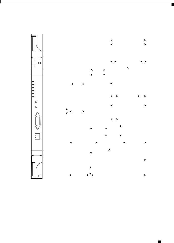
Chapter 2 Cards Specifications
2.2.1 Common Control Cards
Figure 2-3 MS-ISC-100T Faceplate and Block Diagram
TCC2P
FAIL
PWR
A B
ACT/STBY
CRIT
MAJ
MIN
REM
SYNC
ACO
ACO
LAMP
RS-232
TCP/IP
|
|
|
|
|
|
|
|
|
|
|
|
|
|
|
|
|
|
|
|
|
|
|
|
|
|
|
|
|
|
|
|
|
|
|
|
|
BACKPLANE |
|
|
|
|
|
|
|
|
|
|
|
|
|
|
|
|
|
|
|
|
|
|
|
|
|
|
|
|
|
|
|
|
|
|
|
|
|
Ref Clocks |
|
|
|
|
|
|
|
|
|
|
|
|
|
|
|
|
|
|
|
|
|
|
|
|
|
|
|
|
|
|
|
|
|
|
|
|
|
|
|
-48V PWR |
|
|
|
|
|
|
|
|
System |
|
|
|
|
|
|
|
|
|
|
|
|
|
|
|
(all I/O Slots) |
|||||||||||
|
Monitors |
|
|
|
|
|
|
|
|
|
|
|
|
|
|
|
|
|
|
|
|
|
|
|
|
||||||||||||
|
|
|
|
|
|
|
|
|
|
Timing |
|
|
|
|
|
|
|
|
|
|
|
|
|
|
|
BITS Input/ |
|||||||||||
|
|
|
|
|
|
|
|
|
|
|
|
|
|
|
|
|
|
|
|
|
|
|
|
|
|
|
|
|
|||||||||
|
|
|
|
|
|
|
|
|
|
|
|
|
|
|
|
|
|
|
|
|
|
|
|
|
|
|
|
|
|
|
|
|
|
|
|
|
|
|
|
|
|
|
|
|
|
|
|
|
|
|
|
|
|
|
|
|
|
|
|
|
|
|
|
|
|
|
|
|
|
|
|
|
|
|
Output |
|
|
|
|
|
|
|
|
|
|
|
|
|
|
|
FPGA |
|
|
|
|
|
|
|
|
|
|
|
|
|
|
|
|||||||
|
Real Time |
|
|
|
|
|
|
|
|
|
|
|
|
|
|
|
|
|
|
|
|
|
|
|
|
|
|
||||||||||
|
|
|
|
|
|
|
|
|
|
|
|
|
|
|
|
|
|
|
|
|
|
|
|
|
|
|
|
|
|
|
|
|
|
||||
|
|
|
|
|
|
|
|
|
|
|
|
|
|
|
|
|
|
|
|
|
|
|
|
|
|
|
|
|
|
|
|
||||||
|
Clock |
|
|
|
|
|
|
|
|
|
|
DCC |
|
|
|
|
|
TCCA ASIC |
|
|
|
|
SCL Links to |
||||||||||||||
|
|
|
|
|
|
|
|
|
|
|
|
|
|
|
|
|
|
SCL Processor |
|
|
|
|
All Cards |
||||||||||||||
|
|
|
|
|
|
|
|
|
|
|
|
Processor |
|
|
|
|
|
|
|
||||||||||||||||||
|
|
|
|
|
|
|
|
|
|
|
|
|
|
|
|
|
|
|
|||||||||||||||||||
|
|
|
|
|
|
|
|
|
|
|
|
|
|
|
|
|
|
|
|
|
|
|
|
|
|
|
|
||||||||||
|
|
|
|
|
|
|
|
|
|
|
|
|
|
|
|
|
|
|
|
|
|
|
|
|
|
|
|
|
|
|
|
|
|
|
|
|
|
|
|
|
|
|
|
|
|
|
|
|
|
|
|
|
|
|
|
|
|
|
|
|
|
|
|
|
|
|
|
HDLC |
|
||||||
|
|
|
|
|
|
|
|
|
|
|
|
|
|
|
|
|
|
|
|
|
|
|
|
|
|
|
|
|
|
|
|||||||
|
|
|
|
|
|
|
|
|
|
|
|
|
|
|
|
|
|
|
|
|
|
|
|
|
|
|
|
|
|
|
|||||||
|
|
|
|
|
|
|
|
|
|
|
|
|
|
|
|
|
|
|
|
|
|
|
|
|
|
|
|
|
|||||||||
|
|
|
|
|
|
|
|
|
|
MCC1 |
|
|
MCC2 |
|
|
|
|
|
|
|
|
Message |
|
||||||||||||||
|
|
|
|
|
|
|
|
|
|
|
|
|
|
|
|
|
|
|
|||||||||||||||||||
|
|
Serial |
|
|
|
|
|
|
SMC1 |
|
|
|
SCC2 |
|
|
|
|
|
|
|
|
Bus |
|
||||||||||||||
|
|
Debug |
|
|
|
|
|
|
|
|
|
|
|
|
|
|
|
|
|
|
|
|
|
|
|
|
|
||||||||||
|
|
|
|
|
|
|
|
|
|
|
|
|
|
|
|
|
|
|
|
|
|
|
|
|
|
|
|
|
|
|
|
|
|
|
|
||
|
|
|
|
|
|
|
|
|
|
|
|
|
|
|
|
|
|
|
|
|
|
|
|
|
|
|
|
|
|
|
|
|
|
|
|
|
Modem |
|
|
|
|
|
|
|
|
|
|
|
|
|
|
|
|
|
|
|
|
|
|
|
|
|
|
|
Modem |
|
|
|
|
|
|
||||
|
|
|
|
|
|
|
|
|
|
|
|
|
|
|
|
|
|
SCC3 |
|
|
|
|
|
|
|
|
|
|
Interface |
||||||||
|
|
|
|
|
|
|
|
|
|
|
|
|
|
|
|
|
|
|
|
|
|
|
Interface |
|
|
|
|
|
|
||||||||
|
|
400MHz |
|
|
|
|
|
|
|
|
|
|
|
|
|
|
|
|
|
|
|
|
|
|
|
|
|
(Not Used) |
|||||||||
|
|
|
|
|
|
|
|
|
|
|
|
|
|
|
|
|
|
|
|
|
|
|
|
|
|
|
|
|
|
|
|
||||||
|
Processor |
|
|
|
|
|
|
|
|
|
|
|
FCC1 |
|
|
|
|
|
|
|
|
|
|
|
|
|
|
|
Mate TCC2 |
||||||||
|
|
|
|
|
|
|
|
|
|
|
|
|
|
|
|
|
|
|
|
|
|
|
|
|
|
|
|
|
|
|
|
|
|||||
|
|
|
|
|
|
|
|
|
|
Communications |
|
|
|
|
|
|
|
|
|
|
|
|
|
|
|
HDLC Link |
|||||||||||
|
|
|
|
|
|
|
|
|
|
|
|
|
|
|
|
|
|
|
|
|
|
|
|
|
|||||||||||||
|
|
|
|
|
|
|
|
|
|
|
|
|
|
|
|
|
|
|
|
|
|
|
|
|
|
||||||||||||
|
|
|
|
|
|
|
|
|
|
|
|
|
|
|
|
|
|
|
|
|
|
|
|
|
|
||||||||||||
|
|
|
|
|
|
|
|
|
|
|
Processor |
|
|
|
|
|
Ethernet |
|
|
|
|
|
|
|
|||||||||||||
|
SDRAM Memory |
|
|
|
|
|
|
|
|
|
|
|
|
|
|||||||||||||||||||||||
|
|
|
|
|
|
|
|
|
|
|
|
SCC1 |
|
|
|
|
|
|
|
|
|
|
|
||||||||||||||
|
|
|
|
|
|
|
|
|
|
|
|
|
|
|
|
|
|
|
Phy |
|
|
|
|
|
|
|
|||||||||||
|
& Compact Flash |
|
|
|
|
|
|
|
|
|
|
|
|
|
|
|
|
|
|
|
|
|
|
|
|
|
|
|
|
||||||||
|
|
|
|
SCC4 |
|
|
|
FCC2 |
|
|
|
|
|
|
|
|
|
|
|
|
|
|
|
|
|||||||||||||
|
|
|
|
|
|
|
|
|
|
|
|
|
|
|
|
|
|
|
|
|
|
|
|
|
|
|
|
Backplane |
|||||||||
|
|
|
|
|
|
|
|
|
|
|
|
|
|
|
|
|
|
|
|
|
|
|
|
|
|
|
|
|
|
|
|
|
|
|
|
|
|
|
|
|
|
|
|
|
|
|
|
|
|
|
|
|
|
|
|
|
|
|
|
|
|
|
|
|
|
|
|
|
|
|
|
|
|
|
|
|
|
|
|
|
|
|
|
|
|
|
|
|
|
|
|
|
|
|
|
|
|
|
|
|
|
|
|
|
|
|
|
|
|
|
|
|
|
|
|
|
|
|
|
|
|
|
|
|
|
|
|
|
|
|
|
|
|
|
|
|
|
|
|
|
|
|
|
|
|
|
|
|
|
|
|
Faceplate |
|
|
|
|
|
|
|
|
|
|
|
Ethernet Switch |
|
|
|
|
|
|
|
|
|
Ethernet Port |
|||||||||||||||
Ethernet Port |
|
|
|
|
|
|
|
|
|
|
|
|
|
|
|
|
|
|
|
(Shared with |
|||||||||||||||||
|
|
|
|
|
|
|
|
|
|
|
|
|
|
|
|
|
|
|
|
|
|
|
|
|
|
|
|
|
|
||||||||
|
|
|
|
|
|
|
|
|
|
|
|
|
|
|
|
|
|
|
|
|
|
|
|
|
|
|
|
|
|
|
|
|
|
|
|
|
Mate TCC2) |
|
|
|
|
|
|
|
|
|
|
|
|
|
|
|
|
|
|
|
|
|
|
|
|
|
|
|
|
|
|
|
|
|
|
|
|
|
|
|
|
|
|
|
|
|
|
|
|
|
|
|
|
|
|
|
|
|
|
|
|
|
|
|
|
|
|
|
|
|
|
|
|
|
|
|
Mate TCC2 |
|
|
|
|
|
|
|
|
|
|
|
|
|
|
|
|
|
|
|
|
|
|
|
|
|
|
|
|
|
|
|
|
|
|
|
|
|
|
|
|
|
|
|
|
|
|
|
|
|
|
|
|
|
|
|
|
|
|
|
|
|
|
|
|
|
|
|
|
|
|
|
|
|
|
|
|
|
|
|
|
|
|
|
|
EIA/TIA 232 |
|
|
|
|
|
|
|
|
|
|
|
|
|
|
|
|
|
|
|
||||||||||
|
|
|
|
|
|
|
|
|
|
|
|
|
|
|
|
|
|
|
|
|
|
|
|
|
|
|
Ethernet Port |
||||||||||
|
|
|
|
|
|
|
|
Craft Interface |
|
|
|
|
|
|
|
|
|
|
|
|
|
|
|
|
|
|
|
||||||||||
|
|
|
|
|
|
|
|
|
|
|
|
|
|
|
|
|
|
|
|
|
|
|
|
|
|
|
|
||||||||||
Faceplate |
|
|
|
|
|
|
|
|
|
|
|
|
|
|
|
|
|
|
|
|
|
|
|
|
|
|
|
|
|
|
Backplane |
||||||
|
|
|
|
|
|
|
|
|
|
|
|
|
|
|
|
|
|
|
|
|
|
|
|
|
|
|
|
|
|
||||||||
|
|
|
|
|
|
|
|
|
|
|
|
|
|
|
|
|
|
|
|
|
|
|
|
|
|
|
|
|
|
||||||||
|
|
|
|
|
|
|
|
|
|
|
|
|
|
|
|
|
|
|
|
|
|
|
|
|
|
|
|
|
|
EIA/TIA 232 Port |
|||||||
EIA/TIA 232 Port |
|
|
|
|
|
|
|
|
|
|
|
|
|
|
|
|
|
|
|
|
|
|
|
|
|
|
|
|
|
|
|
|
|
(Shared with |
|||
|
|
|
|
|
|
|
|
|
|
|
|
|
|
|
|
|
|
|
|
|
|
|
|
|
|
|
|
|
|
|
|
||||||
|
|
|
|
|
|
|
|
Note: Only 1 EIA/TIA 232 Port Can Be Active - |
Mate TCC2) |
||||||||||||||||||||||||||||
|
|
|
|
|
|
|
Backplane Port Will Supercede Faceplate Port |
|
|||||||||||||||||||||||||||||
|
|
|
|
|
|
|
|
|
|
|
|
|
|
|
|
|
|
|
|
|
|
|
|
|
|
|
|
|
|
|
|
|
|
|
|
|
|
145942
The MS-ISC-100T separates internal and external traffic using a VLAN.
A Cisco IOS configuration file assigns a specific role to each of MS-ISC-100T ports that are shown on the card faceplates. They are as follows:
•DCN Port: Connected to external supervision
•SSC Port: Connected to a TCC2/TCC2P equipped in a subtended shelf
•NC Port: Connected to a TCC2/TCC2P equipped in an NC shelf
Cisco ONS 15454 DWDM Engineering and Planning Guide, Release 7.x
|
July 2006 |
2-17 |
|
|
|
 Loading...