


CTK-530
ELECTRONIC KEYBOARD
CTK-530
(with price)

— 2 —
CONTENTS
Specifications . . . . . . . . . . . . . . . . . . . . . . . . . . . . . . . . . . . . . . . . . . 2
Block Diagram . . . . . . . . . . . . . . . . . . . . . . . . . . . . . . . . . . . . . . . . . 3
Circuit Description . . . . . . . . . . . . . . . . . . . . . . . . . . . . . . . . . . . . . 4
Major waveforms . . . . . . . . . . . . . . . . . . . . . . . . . . . . . . . . . . . . . . 9
PCB View and Check Points . . . . . . . . . . . . . . . . . . . . . . . . . . . . . . 10
Schematic Diagrams . . . . . . . . . . . . . . . . . . . . . . . . . . . . . . . . . . . . 11
Exploded View . . . . . . . . . . . . . . . . . . . . . . . . . . . . . . . . . . . . . . . . 13
Parts List . . . . . . . . . . . . . . . . . . . . . . . . . . . . . . . . . . . . . . . . . . . . 15
SPECIFICATIONS
GENERAL
Number of keys: 61
Polyphonic: 24-note
Preset tones: 64
Keyboard controls: Touch response: On/Off,
Key transpose: Range from F# to F by a semitone increment
Auto-rhythms: 64, Tempo control: 40 to 255
Auto-accompaniment: Mode: CASIO Chord/Fingered/Full-Range Chord 1/Full-Range Chord 2
Controller: Fill-In, Synchro/Ending
Digital volume controls: Main volume: 10 steps
Accompaniment volume: 100 steps
Demo tunes: 3, A Night has 9000 Bars (arranged and programmed byThomas Hirsch)
Wanting This (Edward Alstrom)
Supersonic Remorse (Edward Alstrom)
Tuning control: 440Hz ± 50 cents
Built-in speakers: 12 cm dia. 2 W input rating: 2 pcs.
MIDI: 16 multi-channel reception
Terminals: Phone Jack [Output impedance: 50 Ω, Output voltage: 4.0 V(rms) MAX],
MIDI Jacks (IN, OUT), AC Adapter Jack (9 V)
Auto power off: Approximately 6 minutes after the last operation
Power source: 2-way AC or DC source
AC: AC adapter AD-5
DC: 6 D size dry batteries
Battery life: approx. 5 hours by manganese batteries R20P/SUM-1
Power consumption: 7.7 W
Dimensions (HWD): 99 x 931 x 326 mm (3-7/8 x 36-5/8 x 12-13/16 inches)
Weight: 4.4 kg (9.7 lbs) excluding batteries
ELECTRICAL
Current Drain with 9 V DC:
No Sound Output 180 mA ± 20%
Maximum Volume 825 mA ± 20%
with keys C3 to E4 pressed in Synth-Lead 1 tone
Volume: maximum, Touch response: maximum
— 3 —
Headphone output level (Vrms with 8 Ω load each channel):
with key C3 pressed in Pan Flute tone 210 mV ± 20%
Output level (Vrms with 47 kΩ load each channel):
with key C2 pressed in Pan Flute tone 2000 mV ± 20%
Speaker output level (Vrms with 4 Ω load each channel):
with key A1 pressed in Pan Flute tone 2150 mV ± 20%
Minimum operating voltage: 6.3 V
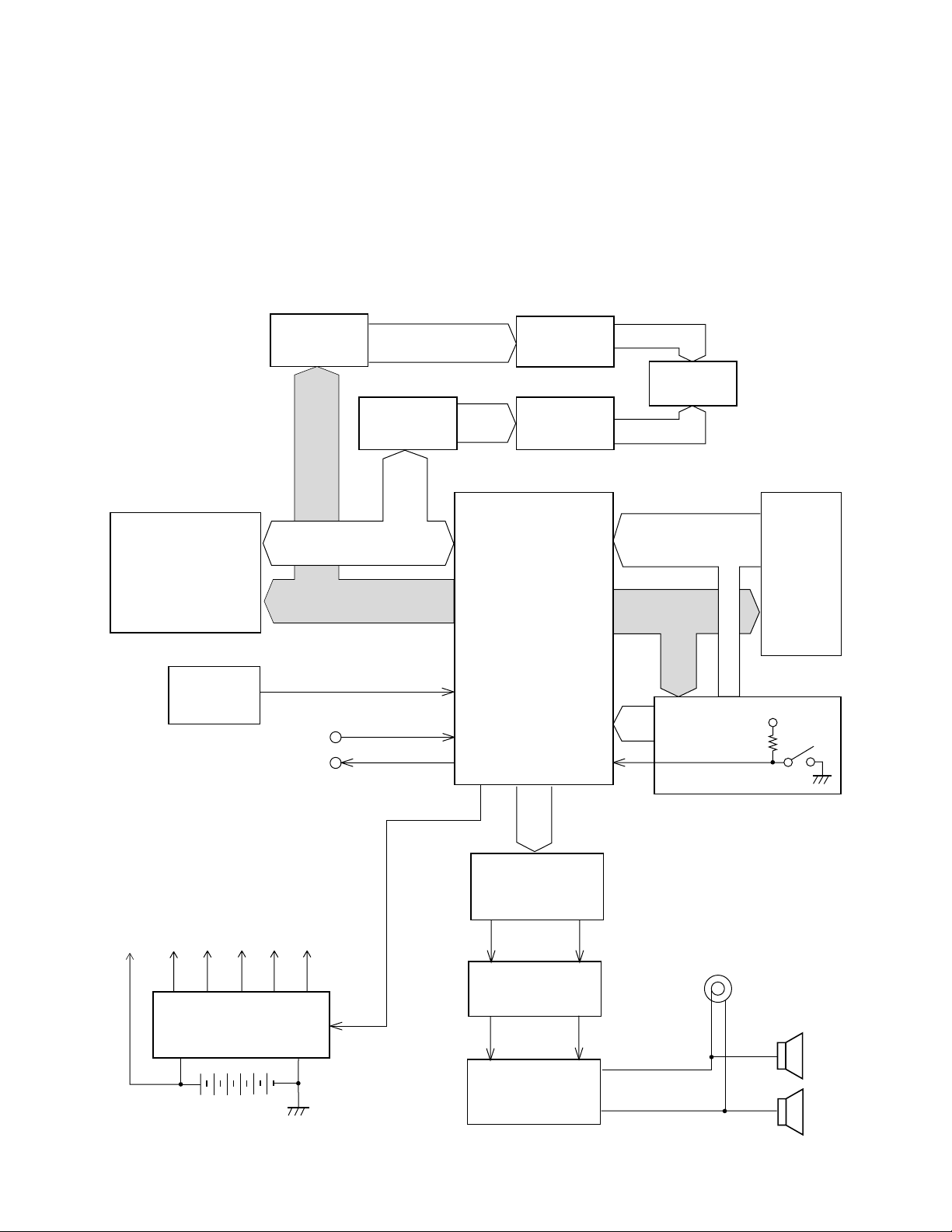
BLOCK DIAGRAM
KC0 ~ KC7
FI0 ~ FI7
SI0 ~ SI7
Sound Source ROM
(8M-bit)
LSI102
MX23C8100MC-
12CA19
LRCK, SO, BCK
D/A Converter
IC103
UPD6379GR
Filter
Q108, Q109
Power Amplifier
IC101
LA4598
LED driver
IC106
BA612
Keyboard
MA0 ~ MA19
Power Supply Circuit
Q101 ~ Q105, Q110, Q119
D104, D105, D109
VCC
AVDD
VDD
LVDD
DVDD
VC
APO
MD0
~
MD7
Speakers
Output
MA8
~
MA11
LEDs /
7Seg. LED
LED driver
Q111 ~ Q118
La ~ Lg, Lp
MIDI
IN
OUT
Buttons
VDD
Power Switch
Reset IC
IC104
RE5VA35AA
RESET
FI10
CPU
LSI101
UPD912GF-3BA
KI0
~ KI2
MD0 ~ MD15
LED Latch
IC105
HD74HC75P
LED Latch
IC107
HD74HC373P
NMI
— 4 —
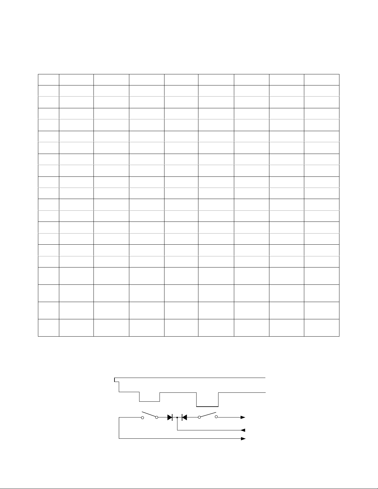
Key
Second contact (2)
First contact (1)
FI
KC
SI
KC0 KC1 KC2 KC3 KC4 KC5 KC6 KC7
FI0 C2 (1) C#2 (1) D2 (1) D#2 (1) E2 (1) F2 (1) F#2 (1) G2 (1)
SI0 C2 (2) C#2 (2) D2 (2) D#2 (2) E2 (2) F2 (2) F#2 (2) G2 (2)
FI1 G#2 (1) A2 (1) A#2 (1) B2 (1) C3 (1) C#3 (1) D3 (1) D#3 (1)
SI1 G#2 (2) A2 (2) A#2 (2) B2 (2) C3 (2) C#3 (2) D3 (2) D#3 (2)
FI2 E3 (1) F3 (1) F#3 (1) G3 (1) G#3 (1) A3 (1) A#3 (1) B3 (1)
SI2 E3 (2) F3 (2) F#3 (2) G3 (2) G#3 (2) A3 (2) A#3 (2) B3 (2)
FI3 C4 (1) C#4 (1) D4 (1) D#4 (1) E4 (1) F4 (1) F#4 (1) G4 (1)
SI3 C4 (2) C#4 (2) D4 (2) D#4 (2) E4 (2) F4 (2) F#4 (2) G4 (2)
FI4 G#4 (1) A4 (1) A#4 (1) B4 (1) C5 (1) C#5 (1) D5 (1) D#5 (1)
SI4 G#4 (2) A4 (2) A#4 (2) B4 (2) C5 (2) C#5 (2) D5 (2) D#5 (2)
FI5 E5 (1) F5 (1) F#5 (1) G5 (1) G#5 (1) A5 (1) A#5 (1) B5 (1)
SI5 E5 (2) F5 (2) F#5 (2) G5 (2) G#5 (2) A5 (2) A#5 (2) B5 (2)
FI6 C6 (1) C#6 (1) D6 (1) D#6 (1) E6 (1) F6 (1) F#6 (1) G6 (1)
SI6 C6 (2) C#6 (2) D6 (2) D#6 (2) E6 (2) F6 (2) F#6 (2) G6 (2)
FI7 G#6 (1) A6 (1) A#6 (1) B6 (1) C7 (1)
SI7 G#6 (2) A6 (2) A#6 (2) B6 (2) C7 (2)
FI10 +-0
Accomp.
Volume Up
Main Vol.
Up
Mode
KI0 Demo 3 2 1
Tempo
Up
Main Vol.
Down
Intro/
Fill-In
KI1
Transpose
Tune/MIDI
6 5 4 Rhythm
Accomp.
Vol. Down
Synchro/
Ending
KI2
Touch
Response
9 8 7 Tone
Tempo
Down
Start/
Stop
CIRCUIT DESCRIPTION
KEY MATRIX
Note: Each key has two contacts, the first conatct (1) and second contact (2).
— 5 —
CPU
LSI101
UPD912GF-3BA
Sound Source ROM
LSI102
MX23C8100PC-12CA19
CE
A0 ~ A18 D0 ~ D15
MA1 ~
MA19
MD0 ~
MD15
MSB0
FI0 ~ FI7
SI0 ~ SI7
SO
BOK
LRCK
PG
X101
20 MHz
DAC
IC103
UPD6379GR
LOUT
ROUT
SO: Sound data
BOK: Bit clock
LRCK: Word clock
SI
CLK
LRCK
From keyboard
Reset IC
IC104
RE5VA35AA
Power Supply Circuit
VDD
Battery set
RESET
VDD
POWER
From power switchNMI
APO
CPU
LSI101
UPD912GF-3BA
SCKO
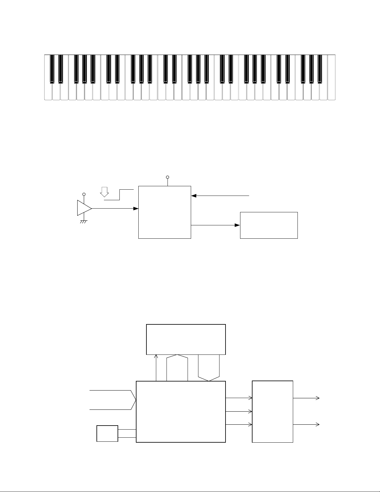
NOMENCLATURE OF KEYS
RESET CIRCUIT
When batteries are set or an AC adapter is connected, the reset IC provides a low pulse to the CPU. The CPU
then initializes its internal circuit.
When the power switch is pressed, the CPU receives a low pulse of POWER signal.The CPU raises APO signal
to +5 V to turn power on.
CPU (LSI101: UPD912GF-3BA)
The 16-bit CPU contains a 1k-byte RAM, three 8-bit I/O ports, two timers, a keycontroller and serial interfaces.
The CPU detects key velocity by counting the time between first-key input signal FI and second-key SI from
the keyboard. The CPU reads sound data and velocity data from the sound source ROM in accordance with
the selected tone; the CPU can read rhythm data simultaneously when a rhythm pattern is selected. Then the
CPU provides 16-bit serial sound data to the DAC.The CPU also controls MIDI input/output and LED driving.
F#3 G#3
A#3 C#4 D#4
F#4 G#4
A#4
C#5
D#5
F#5 G#5
A#5
F3 G3 A3 B3 C4 D4 E4 F4 G4 A4 B4 C5 D5 E5 F5 G5 A5 B5
C6
D#3
C2 D2
E2
F2
G2
A2 B2 C3 D3
E3
B6A6G6F6E6D6
C7
C#3A#2G#2
F#2D#2
C#2
A#6
G#6F#6D#6
C#6
— 6 —
The following table shows the pin functions of LSI101.
DAC (IC103: UPD6379GR)
The DAC receives 16-bit serial data output from the CPU. The data contains digital sound data of the melody,
chord, bass, and percussion for the right and left channels. The DAC converts the data into analog waveforms
and output them to each channel separately.
Pin No. Terminal In/Out Function
1 TXD0 Out MIDI signal input
2 RXD0 In MIDI signal output
3 SCK0 Out APO (Auto Power Off) signal output
4 ~ 6 Not used. Connected to ground.
7 AVCC In Ground (0 V) source
8, 9 AN0, AN1 Not used. Connected to ground.
10 AGND In Ground (0 V) source
11 BCK Out Bit clock output
12 SO Out Serial sound data output
13 LRCK Out Word clock output
14 GND In Ground (0 V) source
15, 16 XLT0, XLT1 In/Out 20 MHz clock input/output
17 VCC In +5 V source
18, 19 MD0, MD1 In Mode selection terminal. Connected to ground.
20 RSTB In Reset signal input
21 NMI In Power ON signal input
22 INT Not used. Connected to ground.
23 ~ 30
FI0 ~ FI3
SI0 ~ SI3
In Key input signal
31 ~ 38 KC0 ~ KC7 Out Key scan signal output
39 ~ 46
FI4 ~ FI7
SI4 ~ SI7
In Key input signal
47 ~ 50 In Not used.
51 FI10 In Button input signal input
52 SI10 In Not used
53 ~ 55 KI0 ~ KI2 In Button input signal input
56 MWNB Out Not used.
57 ~ 76 MA1 ~ MA17 Out Address bus
77 MCSB0 Out Chip enable signal output for the sound source ROM
78, 79 Out Not used
80 VCC In +5 V source
81 GND In Ground (0 V) source
82 MRDB Out Read enable signal output for the sound source ROM
83 ~ 98 MD0 ~ MD15 In/Out Data bus
99 PLE Out Latch enable signal output for LED latches
100 P17 In APO cancellation signal input
 Loading...