


CTK-711EX
JUL.1998
|
110 RHYTHMS |
|
|
|
|
|
|
|
|
|
|
|
|
|
|
|
|
232 TONES |
|
|
|
|
|
|
10DSP |
||
|
|
|
|
|
|
DSP |
|
|
|
|
|
|
|
|
|
|
|
|
|
TONE |
|
|
DEMO |
ENVELOPE |
PARAMETER RESET |
||
|
|
|
|
|
|
|
|
|
|
|
|
|
|
|
|
|
|
|
|
|
7 |
8 |
9 |
PITCH |
AMP |
ENTER |
|
|
|
|
|
|
|
|
|
|
|
|
|
|
|
|
|
|
|
|
|
|
ENVELOPE |
ENVELOPE |
|
||||
|
|
|
|
|
|
|
|
|
|
|
|
|
|
|
|
|
|
|
|
|
|
|
|
SYNTH |
|
|
|
USER RHYTHM |
|
|
|
|
|
CONTRAST |
|
|
|
|
|
|
|
|
|
|
|
|
|
RHYTHM |
|
|
|
|
|
|
|
100 ‘109 |
POWER |
MODE |
VOLUME |
|
|
|
|
|
|
|
|
|
|
|
|
|
|
|
|
4 |
5 |
6 |
TRANSPOSE/ |
|
|
|
|
|
|
FULL RANGE |
|
|
|
|
|
|
|
|
|
|
|
|
|
|
|
|
|
TUNE/MIDI |
|
|
|
||||
|
|
CHORD |
|
|
FREE |
|
|
|
|
|
|
|
|
|
|
|
|
|
LAYER/ |
|
|
|
|
|
|
||
|
|
FINGERED |
MAX |
|
SESSION |
|
|
|
|
|
|
|
|
|
|
|
|
|
AUTO HARMONIZE |
|
|
|
|
|
|
||
|
|
|
|
|
|
|
|
|
|
|
|
|
|
|
|
|
|
|
1 |
2 |
3 |
TOUCH |
|
|
|
||
|
|
CASIO CHORD |
|
|
|
|
|
|
|
|
|
|
|
|
|
|
|
|
|
RESPONSE |
|
|
|
||||
|
|
|
|
ONE TOUCH |
|
|
|
|
|
|
|
|
|
|
|
|
|
|
|
|
|
|
|
|
|
||
|
|
|
|
MIN |
|
PRESET |
|
|
|
|
|
|
|
|
|
|
|
|
|
SPLIT |
/NO |
/YES |
DISK |
|
|
|
|
|
|
|
|
|
|
|
|
|
|
|
|
|
|
|
|
|
|
|
|
0 |
|
|
|
|
|
||
|
|
|
|
|
|
|
|
|
|
|
|
|
|
|
|
|
|
|
|
|
|
|
|
|
|
|
|
|
|
SEQUENCER |
|
|
|
|
|
|
|
16 CHANNEL MIXER |
|
|
|
|
|
|
|
DELETE |
|
|
|
|
|
||||
|
|
|
|
|
|
EXTERNAL |
CH1 |
CH2 |
CH3 |
CH4 |
CH5 CH6 |
CH7 |
CH8 |
CH9 |
CH10 |
CH11 |
CH12 |
CH13 |
CH14 |
CH15 |
CH16 |
CURSOR |
MAIN MENU/ |
: |
|
|
|
|
RECORD |
|
SONG |
PATTERN |
|
|
|
|
|
|
|
|
|
|
|
|
|
|
|
|
|
|
|
SUB MENU/ |
: |
|
|
|
|
|
|
|
|
INTERNAL |
UPPER1 |
UPPER2 |
LOWER1 LOWER2 ACC VOL. CHORD1 |
CHORD2 CHORD3 |
BASS |
RHYTHN |
TR1 |
TR2 |
TR3 |
TR4 |
TR5 |
TR6 |
|
|
CHANNEL SELECT |
|
|
||||
|
|
|
|
|
|
MIXER SELECT |
|
TONE EXPANDER |
|
ACCOMP |
|
|
|
|
SEQUENCER TRACK |
|
|
|
|
|
|
|
|||||
|
INTRO |
NORMAL/ |
VARIATION/ |
SYNCHRO/ |
START/ |
TEMPO |
|
|
|
|
|
|
REGISTRATION |
|
|
|
|
|
|
|
|
|
|
|
|
|
|
|
FILL-IN |
FILL-IN |
ENDING |
STOP |
|
|
|
|
BANK |
A |
B |
C |
|
D |
|
E |
STORE |
|
|
|
|
ENTER |
|
|
|
||
2-WAY |
|
|
|
|
|
|
|
|
|
|
|
|
|
|
|
|
|
|
|
|
|
|
|
|
2-WAY |
|
|
BASS REFLEX SPEAKER |
|
|
|
|
|
|
|
|
|
|
|
|
|
|
|
|
|
|
|
|
|
|
|
BASS REFLEX SPEAKER |
|
||
MODULATION |
|
PITCH |
BEND |
CTK-711
INDEX
GM SOUND KEYBOARD
|
CONTENTS |
Safety Notice ----------------------------------------------------------------------------------------------- |
2 |
Specifications ---------------------------------------------------------------------------------------------- |
3 |
Important Operation ------------------------------------------------------------------------------------- |
5 |
Block Diagram --------------------------------------------------------------------------------------------- |
6 |
Circuit Description --------------------------------------------------------------------------------------- |
7 |
Diagnostic Program ------------------------------------------------------------------------------------ |
20 |
Major Waveforms --------------------------------------------------------------------------------------- |
25 |
Printed Circuit Board ---------------------------------------------------------------------------------- |
26 |
Exploded View ------------------------------------------------------------------------------------------- |
28 |
Parts List --------------------------------------------------------------------------------------------------- |
29 |
Schematic Diagrams ----------------------------------------------------------------------------------- |
31 |
— 1 —

SAFETY NOTICE
CAUTION!
Danger of explosion if battery is incorrectly replaced. Replace only with the same or equivalent type.
DENMARK:
ADVARSE!
Lithiumbatteri. Eksplosionsfare ved fejlagtig handtering. Udskiftning ma kun ske med batteri af samme fabrikat og type. Lever det brugte batteri tilbage tili leverandoren.
FINLAND:
VAROITUS
Paristo voiäjähtää, jos se on virheellisesti asennettu. Vaihda paristo ainoastaan valmistajan suosittelemaan tyyppiin. Hävitä käytetty paristo valmistajan ohjeiden mukaisesti.
SWEDEN:
VARNING
Felaktigt batteribyte kan medf fara för explosion. Använd därför endast samma typ eller likvärdig typ enligt apparattillverkarens rekommendation.
Kassera förbrukade batterier enligt tillverkarens anvisning.
— 2 —

|
SPECIFICATIONS |
GENERAL |
|
Keyboard: |
61 standard-size keys, 5 octaves (with touch response on/off; ExLight/ |
Tones: |
Light/Normal/Heavy touch) |
232 (128 General MIDI, 64 variation, 8 drum, 32 user); with layer and |
|
Rhythm instrument tones: |
split |
53 |
|
Polyphony: |
32 notes maximum (16 for certain tones) |
Digital effects: |
10 (REVERB 1, 2, 3; CHORUS; TREMOLO; PHASE SHIFTER; OR- |
Auto accompaniment |
GAN SPEAKER; ENHANCER; FLANGER; EQ LOUDNESS) |
|
|
Rhythm patterns: |
110 (100 + 10 user rhythms) |
Tempo: |
Variable (226 steps, = 30 to 255) |
Chords: |
3 fingering methods (CASIO CHORD, FINGERED, FULL RANGE |
|
CHORD) |
Rhythm controller: |
Start/Stop, Intro, Normal/Normal Fill-In, Variation/Variation Fill-In, |
|
Synchro/Ending |
Accomp volume: |
0 to 127 (128 steps) |
One touch presets: |
Recalls settings for tone, tempo, layer, and Auto Harmonize in accor- |
|
dance with rhythm. |
Auto harmonize: |
Automatic addition of notes that harmonize with melody note in ac- |
Free session |
cordance with specified Auto Accompaniment chords. |
|
|
Number of patterns: |
100 (Auto Accompaniment function based on preset chord progres- |
Song sequencer |
sions.) |
|
|
Songs: |
2 |
Recording tracks: |
6 (2 through 6 are melody tracks) |
Recording method: |
Real-time |
Memory capacity |
|
(total for two songs): |
Approximately 4,500 notes |
Punch in: |
Supported |
Pattern sequencer |
|
Number of patterns: |
10 (Rhythm numbers 100 to 109) |
Memory capacity: |
Approximately 4,700 notes |
Elements: |
Intro, Normal, Variation, Normal Fill-In, Variation Fill-In, Ending |
Parts: |
Chord 1, 2, 3; Bass; Rhythm |
Recording method: |
Real-time |
Registration memory |
20 (5 setups × 4 banks) |
Number of setups: |
|
Memory contents: |
Tone, Rhythm, Tempo, Split on/off, Split point, Layer on/off, Auto Har- |
|
monize on/off, Mixer settings, Keyboard channel on/off, DSP (digital |
|
effect) on/off, DSP (digital effect) settings, Accompaniment mode, |
|
Touch Response settings, Assignable jack setting, Transpose, Tun- |
Demo tunes: |
ing, Pitch Bend range, Sound range shift on/off |
2 |
|
Synthesizer |
|
Parameters: |
PCM set, amp envelope set, attack rate, release rate, pitch envelope |
|
set, pitch, level, touch sensitivity, pan, filter sensitivity, filter level, trans- |
Mixer |
pose |
|
|
Channels: |
16 |
Modes: |
Internal, External, External/Solo, External/Play |
Parameters: |
Program change number, volume, expression, pan, coarse tuning, |
MIDI: |
fine tuning, Effect Send |
16-channel multi-timbre receive, General MIDI Level 1 |
— 3 —

Other functions |
|
|
|
Pitch bend range: |
Adjustable (12 semitones upwards and downwards) |
||
Modulation: |
Equipped |
||
Transpose: |
25 steps (–12 semitones to +12 semitones) |
||
Tuning: |
Adjustable (A4 = approximately 440Hz ± 50 cents) |
||
Terminals |
|
|
|
MIDI terminal: |
IN, OUT |
||
Sustain/Assignable jack: |
Standard jack (sustain, sostenuto, soft, rhythm start/stop) |
||
Headphones/Output: |
Stereo standard jack |
||
|
Output Impedance: 250 Ω |
||
|
Output Voltage: 5 V (RMS) MAX |
||
Power supply: |
12 V DC |
||
Dual power supply system |
|||
Batteries |
Six D-size batteries |
||
Battery life |
Approximately 3 hours continuous operation on alkaline batteries |
||
AC adapter: |
AD-12 |
||
Auto power off: |
Turns power off approximately six minutes after last key operation. En- |
||
Speaker output: |
abled under battery power only, can be disabled manually. |
||
5 W + 5 W |
|||
Power consumption: |
12 V |
|
18 W |
|
|||
Dimensions: |
109.2 × 42.7 × 15.7 cm (43 1/16 × 16 13/16 × 6 3/16 inch) |
||
Weight (without batteries): |
Approximately 8.8 kg (19.4 lbs) |
||
Standard accessories: |
Music Stand; Keyboard User’s Guide |
||
ELECTRICAL
Current drain with 12 V DC: |
|
440 mA ± 20 % |
No sound output |
|
|
Maximum volume |
|
2000 mA ± 20 % |
with 10 keys from C3 to E4 pressed in whistle tone |
|
|
Volume: MAX., Velocity: MAX. |
|
|
DSP0: Reverb1, FDD: Replay |
|
|
Phone output level (Vrms with 8 Ω load each channel): |
|
108 mV ± 20 % |
with tone Synth-Bass 4 tone |
L-ch (Key C4) |
|
Volume: MAX., Velocity: MAX. |
R-ch (Key F3) |
102 mV ± 20 % |
DSP0: Reverb1 |
|
|
Speaker output level (Vrms with 8 Ω load each channel): |
|
7.2 mV ± 20 % |
with tone Synth-Bass 4 tone |
L-ch (Key D3) |
|
Volume: MAX., Velocity: MAX. |
R-ch (Key F3) |
6.3 mV ± 20 % |
DSP0: Reverb1 |
|
|
Output level (Vrms with 47 kΩ load each channel): |
|
3600 mV ± 20 % |
with tone Synth-Bass 4 tone |
L-ch (Key C4) |
|
Volume: MAX., Velocity: MAX. |
R-ch (Key F3) |
3200 mV ± 20 % |
DSP0: Reverb1 |
|
|
Minimum operating voltage: |
|
6.1 V |
— 4 —

IMPORTANT OPERATION
Full Initialization
Use this procedure to return all keyboard settings to what they were when you purchased it. Note that this procedure clears all data from memory.
• While holding down the ENTER button, turn on keyboard power.
Re se t?
•Press YES to initialize the keyboard or NO to turn on power without changing any settings.
Parameter Initialization
Use this procedure to return all keyboard settings to what they were when you purchased it. Note that this procedure does not affect user tones, user rhythms, registration memory contents, and display contrast settings.
• While keyboard power is on, press the [+], [–], and ENTER buttons at the same time.
Adjusting Display Contrast
•Display contrast can be adjust to one of 100 levels for easy viewing.
•Adjusting display contrast helps to make figures easier to read from any viewing angle.
•Within five seconds after pressing the CONTRAST button, press [+] to increase the contrast value (making the display darker) or [–] to decrease it (making the display lighter).
•After you release CONTRAST, the message “Contrast” remains on the display for a few moments, during which you can change the contrast setting further using [+] and [–] or by inputting a contrast value with the number keys.
The contrast can be set to a value from 0 to 99. The initial default setting is 50.
GM (General MIDI):
General MIDI standardizes MIDI data to play music with same nuance between different MIDI instruments. Among GM conformed MIDI instruments, or commercially available musical data, music can be played with similar tones.
SMF (Standard MIDI File):
SMF is a standard file format for MIDI instruments and computer music software. SMF formatted data can be played and transported easily among SMF complied instruments or musical data of different manufacturers.
— 5 —
ROM1
MSM27C802CZ-463
LSI2 (8Mbit)
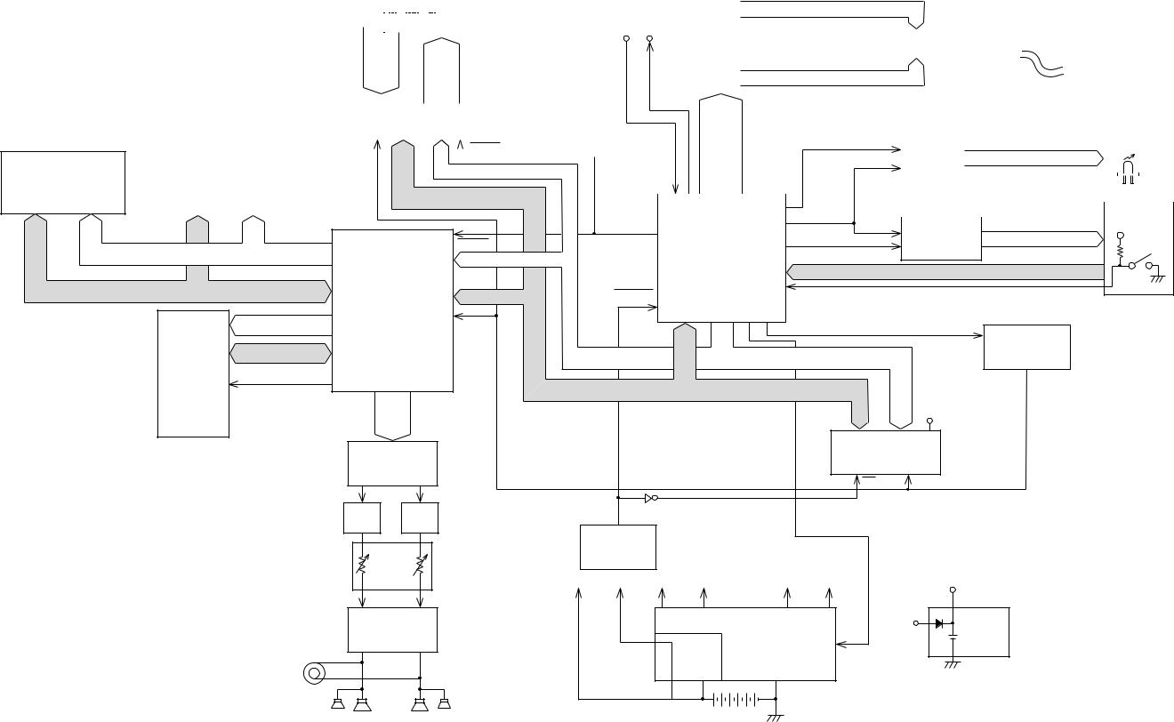
BLOCK DIAGRAM
|
|
|
|
|
Keyboard |
|
|
LCD Driver |
SEG1 ~ SEG40 |
|
|
|
|
|
|
|
|
|
|
|
|
||||||||||||||
|
|
|
|
|
|
|
|
|
|
|
|
|
|
|
|
|
|
|
MIDI |
|
|
|
|
|
|
|
|
|
|
|
|
||||
|
|
|
|
|
|
|
|
|
|
|
|
|
|
|
|
|
|
|
|
|
|
|
|
|
|
|
|
|
|
|
|
|
|||
|
|
|
|
|
|
|
|
|
|
|
|
|
|
|
|
|
|
|
IN OUT |
SED1278F2A |
|
|
|
|
|
|
|
|
|
|
|
|
|
|
|
|
|
|
SI0 ~ |
|
|
|
|
|
|
KC0 |
|
|
|
LCD |
|
Back Light |
|
|
|
|
|
|
|
||||||||||||
|
|
|
SI7 |
|
|
|
|
|
|
|
|
|
|
|
|
|
Back Light Driver |
|
|
||||||||||||||||
|
|
|
|
|
|
|
|
|
|
|
|
||||||||||||||||||||||||
|
|
|
FI0 ~ |
~ |
|
|
|
|
|
LSI501 |
|
|
|
|
|
|
|
|
|
||||||||||||||||
|
|
|
|
|
|
|
|
COM1 ~ COM16 |
|
|
|
|
|
|
|
|
|
|
|
|
|||||||||||||||
|
|
|
FI7 |
|
|
|
|
|
|
KC7 |
|
|
|
|
|
|
|
NT-07 |
|
|
|||||||||||||||
|
|
|
|
|
|
|
|
|
|
|
|
|
|
|
|
|
|
|
|||||||||||||||||
|
|
|
|
|
|
|
|
|
|
|
|
|
|
|
|
|
|
|
|
|
|
|
|
|
|
|
Q501, Q502 |
|
|||||||
|
|
|
Key Controller |
|
|
|
DB4 |
|
|
|
|
|
|
|
|||||||||||||||||||||
|
|
|
TC190C020AF-001 |
|
|
|
|
|
|
|
|
|
|
|
|
|
|
|
|
|
|||||||||||||||
|
|
|
|
|
|
~DB7 |
|
|
|
|
|
|
|
|
|
|
|
|
|
|
|||||||||||||||
|
|
|
|
|
|
|
LSI10 |
|
|
|
|
|
|
|
|
|
|
|
|
|
|
|
|
|
|||||||||||
|
|
|
|
|
|
|
|
|
|
LEDCK, LEDCL |
|
|
|
|
|
|
|
LEDs |
|
||||||||||||||||
|
|
HWR,RD, |
|
|
|
|
|
|
|
|
|
|
|
|
|
|
RESB |
CONT, |
|
|
S-Register |
|
|
|
|
||||||||||
|
|
|
|
|
|
|
|
|
|
|
|
|
|
|
|
|
|
|
|
|
|
|
|
|
|
|
|||||||||
ROM2 |
|
LWR |
|
|
|
|
|
|
|
|
|
|
|
|
|
|
LRS, |
|
|
|
TC74HC164 |
LEDA ~ LEDF |
|
|
|
|
|
||||||||
|
|
|
|
|
|
|
|
|
|
|
|
|
|
|
|
|
|
|
|
|
|
|
|
|
|
|
|
||||||||
MSM23C3210MC |
|
|
|
|
|
|
|
|
|
|
|
|
|
|
|
|
|
A1 ~ A4 |
LR/W |
|
|
|
IC301 |
|
|
|
|
|
|
|
|
||||
|
|
|
|
|
|
|
|
|
|
|
|
|
|
|
|
|
|
|
|
|
|
|
|
|
|
|
|
||||||||
|
|
|
|
|
|
|
|
|
|
|
|
|
|
|
|
|
|
|
|
|
|
|
|
|
|
|
|
||||||||
-12CA89 |
|
|
|
|
|
|
|
|
|
|
|
|
|
|
|
|
|
|
|
|
LE |
|
|
|
|
|
|
|
|
|
|
|
|
|
|
|
|
|
|
|
|
|
|
|
|
|
|
|
|
|
|
|
|
|
|
|
|
|
|
|
|
|
|
|
|
|
|
|
|
||
|
|
|
|
|
|
|
|
|
|
|
|
|
|
D0 ~ D15 |
|
|
|
|
|
|
|
|
|
|
|
|
|
|
|
||||||
LSI3 (32Mbit) |
|
|
|
|
|
|
|
|
|
|
|
|
|
|
|
|
|
|
|
|
|
|
|
|
|
|
|
|
|
||||||
|
|
|
|
|
|
|
|
|
|
|
|
|
|
|
|
|
|
|
|
|
|
|
|
|
|
|
|
|
|
|
Buttons |
||||
|
|
|
|
|
|
|
|
|
|
|
|
|
|
|
|
|
|
|
|
|
|
|
|
|
|
|
|
|
|
|
|
||||
|
|
|
|
|
|
|
|
|
|
|
|
|
|
|
|
|
|
|
|
|
|
|
|
|
|
|
|
|
|
|
|||||
|
|
|
|
|
|
|
|
|
|
|
|
|
|
|
|
|
|
|
|
|
|
|
|
|
|
|
|
|
|
|
|||||
|
|
|
|
|
|
CPU |
|
LSDT |
|
|
S-Register |
|
KC0 ~ KC8 |
VDD |
|
|
|
|
RESB |
PBO |
|
|
TC74HC164 |
|
|||||||
RA0 ~ RA20 |
|
|
|
|
|
SWCK |
|
|
|
||||||
|
|
A0 ~ A3 |
|
HD6473042F16-463 |
|
|
IC302 |
|
|
|
|||||
|
|
|
|
|
|
|
KI0 ~ KI7 |
|
|
|
|||||
|
|
DSP |
|
|
|
|
|
|
|
|
|
|
|
|
|
RD0 ~ RD15 |
|
D8 ~ D15 |
RESET |
LSI9 |
|
NMI |
|
|
|
|
|
|
|||
|
|
|
|
|
|
|
|
|
|
|
|||||
Working |
HG51B155FD |
|
|
|
|
|
|
|
|
|
|
|
|
|
|
EA0 ~ EA14 |
|
RD, |
|
|
|
|
|
1RD, 1HWR, 1LWR |
|
Chip Selector |
|
||||
RAM |
|
LSI4 |
HWR |
|
|
|
|
|
|
|
|
|
|
||
ED0 ~ ED8 |
|
|
|
|
|
|
|
|
|
TC74HC08 |
|
||||
|
|
|
|
|
|
|
A0 ~ A15 |
|
|
|
|
||||
|
|
|
|
|
|
|
|
|
|
|
IC4 |
|
|||
TC55257 |
|
|
|
|
|
|
|
|
|
|
|
|
|||
ECEB, EOEB |
|
|
|
|
|
|
|
|
|
|
|
|
|
|
|
GFL-70L |
|
|
|
|
|
|
|
|
|
|
|
|
|
|
|
EWEB |
|
|
|
|
|
|
D0 ~ D15 |
|
|
|
|
|
|
||
|
WOK1 |
|
|
|
|
|
|
|
|
|
|
|
|||
LSI5 |
|
|
|
|
|
|
|
|
D8 |
|
VBR |
|
|
|
|
|
SOLP |
|
|
|
|
|
|
|
~ |
|
|
|
|
||
(256Kbit) |
|
BOK |
|
|
|
|
|
|
|
D15 |
|
|
HWR,RD, |
LWR |
|
|
|
|
|
|
|
|
|
RAM1 |
|
|
|||||
|
|
|
|
|
|
|
|
|
|
|
|
||||
|
D/A Converter |
|
|
|
|
|
|
|
|
|
|
|
|||
|
|
|
|
|
|
|
|
TC551001BFL-70L |
|
|
|
||||
|
PD6376GS |
|
|
|
|
|
|
|
LSI8 (1Mbit) |
|
|
|
|||
|
|
LSI1 |
|
|
|
|
|
|
|
S1 |
|
HWR, RD |
|
|
|
|
|
|
|
|
|
|
|
|
|
|
|
|
|
||
|
LPF |
LPF |
|
|
IC1 |
|
|
|
|
|
|
|
|
|
|
|
(L) |
(R) |
|
Reset IC |
|
|
|
|
|
|
|
|
|
|
|
|
|
|
|
|
|
|
|
|
|
|
|
|
|
|
|
|
|
Main |
|
RN5VD40A |
|
|
|
|
|
|
|
|
|
|
|
|
|
|
IC3 |
|
|
|
|
|
|
|
|
|
|
|
|
|
Volume |
|
|
|
|
|
|
|
|
|
|
|
|
||
|
VC |
VDD |
VCC |
CVDD |
|
DVDD AVDD |
|
VBR |
|
|
|
||||
|
|
|
|
|
|
|
|
||||||||
|
Power Amp. |
|
|
|
Power Supply Circuit |
|
VDD |
Back up |
|
|
|||||
|
LA4620 |
|
|
|
|
Power |
|
|
|||||||
|
|
|
|
|
|
|
|
|
|
|
|
||||
|
Out put |
IC201 |
|
|
|
Q205, |
Q203, Q204, Q207, |
APO |
|
CR2032 |
|
|
|||
|
|
|
|
|
Q206 |
Q208, Q212, Q213 |
|
|
|
|
|
||||
|
|
|
|
|
|
|
|
|
|
|
|||||
|
(L) |
(R) |
|
|
|
|
|
|
|
|
|
|
|
|
|
|
Speakers |
|
|
|
|
|
|
|
|
|
|
|
|
|
|
|
|
|
— 6 — |
|
|
|
|
|
|
|
|
|
|
|
|

CIRCUIT DESCRIPTION
KEY MATRIX
|
KC0 |
KC1 |
KC2 |
KC3 |
KC4 |
KC5 |
KC6 |
KC7 |
|
|
|
|
|
|
|
|
|
FI0 |
C2 1 |
C#2 1 |
D2 1 |
D#2 1 |
E2 1 |
F2 1 |
F#2 1 |
G2 1 |
|
|
|
|
|
|
|
|
|
SI0 |
C2 2 |
C#2 2 |
D2 2 |
D#2 2 |
E2 2 |
F2 2 |
F#2 2 |
G2 2 |
|
|
|
|
|
|
|
|
|
FI1 |
G#2 1 |
A2 1 |
A#2 1 |
B2 1 |
C3 1 |
C#3 1 |
D3 1 |
D#3 1 |
|
|
|
|
|
|
|
|
|
SI1 |
G#2 2 |
A2 2 |
A#2 2 |
B2 2 |
C3 2 |
C#3 2 |
D3 2 |
D#3 2 |
|
|
|
|
|
|
|
|
|
FI2 |
E3 1 |
F3 1 |
F#3 1 |
G3 1 |
G#3 1 |
A3 1 |
A#3 1 |
B3 1 |
|
|
|
|
|
|
|
|
|
SI2 |
E3 2 |
F3 2 |
F#3 2 |
G3 2 |
G#3 2 |
A3 2 |
A#3 2 |
B3 2 |
|
|
|
|
|
|
|
|
|
FI3 |
C4 1 |
C#4 1 |
D4 1 |
D#4 1 |
E4 1 |
F4 1 |
F#4 1 |
G4 1 |
|
|
|
|
|
|
|
|
|
SI3 |
C4 2 |
C#4 2 |
D4 2 |
D#4 2 |
E4 2 |
F4 2 |
F#4 2 |
G4 2 |
|
|
|
|
|
|
|
|
|
FI4 |
G#4 1 |
A4 1 |
A#4 1 |
B4 1 |
C5 1 |
C#5 1 |
D5 1 |
D#5 1 |
|
|
|
|
|
|
|
|
|
SI4 |
G#4 2 |
A4 2 |
A#4 2 |
B4 2 |
C5 2 |
C#5 2 |
D5 2 |
D#5 2 |
|
|
|
|
|
|
|
|
|
FI5 |
E5 1 |
F5 1 |
F#5 1 |
G5 1 |
G#5 1 |
A5 1 |
A#5 1 |
B5 1 |
|
|
|
|
|
|
|
|
|
SI5 |
E5 2 |
F5 2 |
F#5 2 |
G5 2 |
G#5 2 |
A5 2 |
A#5 2 |
B5 2 |
|
|
|
|
|
|
|
|
|
FI6 |
C6 1 |
C#6 1 |
D6 1 |
D#6 1 |
E6 1 |
F6 1 |
F#6 1 |
G6 1 |
|
|
|
|
|
|
|
|
|
SI6 |
C6 2 |
C#6 2 |
D6 2 |
D#6 2 |
E6 2 |
F6 2 |
F#6 2 |
G6 2 |
|
|
|
|
|
|
|
|
|
FI7 |
G#6 1 |
A6 1 |
A#6 1 |
B6 1 |
C7 1 |
|
|
|
|
|
|
|
|
|
|
|
|
SI7 |
G#6 2 |
A6 2 |
A#6 2 |
B6 2 |
C7 2 |
|
|
|
|
|
|
|
|
|
|
|
|
Note: Each key has two contacts, the first conatct 1 and second contact 2.
Key
|
FI |
Second contact 2 |
First contact 1 |
|
KC |
|
SI |
NOMENCLATURE OF KEYS
C#2 D#2 |
F#2 G#2 A#2 |
C#3 D#3 |
F#3 G#3 A#3 |
C#4 D#4 |
F#4 G#4 A#4 |
C#5 D#5 |
F#5 G#5 A#5 |
C#6 D#6 |
F#6 G#6 A#6 |
C2 |
D2 |
E2 |
F2 |
G2 |
A2 |
B2 |
C3 |
D3 |
E3 |
F3 |
G3 |
A3 |
B3 |
C4 |
D4 |
E4 |
F4 |
G4 |
A4 |
B4 |
C5 |
D5 |
E5 |
F5 |
G5 |
A5 |
B5 |
C6 |
D6 |
E6 |
F6 |
G6 |
A6 |
B6 |
C7 |
— 7 —
BUTTON MATRIX
|
KI0 |
KI1 |
KI2 |
KI3 |
KI4 |
KI5 |
KI6 |
KI7 |
|
|
|
|
|
|
|
|
|
|
|
KC0 |
MODE |
INTRO |
MIXER |
CH8 |
A |
CH16 |
SPLIT |
H/NO |
|
SELECT |
— |
||||||||
|
|
|
|
|
|
|
|||
KC1 |
RECORD |
NORMAL/ |
CH1 |
CH9 |
B |
E |
LAYER/ |
2 |
|
|
|
FILL-IN |
|
|
|
|
AUTO HARMO |
|
|
KC2 |
SONG |
VARIATION/ |
CH2 |
CH10 |
C |
H |
RHYTHM |
5 |
|
FILL-IN |
|||||||||
|
|
|
|
|
|
|
|
||
|
|
|
|
|
|
|
|
|
|
KC3 |
PATTERN |
SYNCHRO/ |
CH3 |
CH11 |
D |
ENTER |
TONE |
8 |
|
|
|
ENDING |
|
|
|
|
|
|
|
KC4 |
DSP |
START/ |
CH4 |
CH12 |
E |
TOUCH |
0 |
G/YES |
|
STOP |
RESPONSE |
+ |
|||||||
|
|
|
|
|
|
||||
|
|
|
|
|
|
|
|
|
|
KC5 |
CON- |
TEMPO |
CH5 |
CH13 |
STORE |
MIDI |
1 |
3 |
|
TRAST |
G |
||||||||
|
|
|
|
|
|
|
|||
|
|
|
|
|
|
|
|
|
|
KC6 |
FREE |
TEMPO |
CH6 |
CH14 |
G |
TRANS- |
4 |
6 |
|
SESSION |
H |
POSE |
|||||||
|
|
|
|
|
|
||||
|
|
|
|
|
|
|
|
|
|
KC7 |
ONE TOUCH |
BANK |
CH7 |
CH15 |
F |
SYNTH |
7 |
9 |
|
PRESET |
|||||||||
|
|
|
|
|
|
|
|
||
|
|
|
|
|
|
|
|
|
|
DMSW |
DEMO |
|
|
|
|
|
|
|
|
|
|
|
|
|
|
|
|
|
LED MATRIX
LED-A |
LED-B |
LED-C |
LED-D |
LED-E |
LED-F |
|
|
|
|
|
|
|
|
FULL RANGE |
FINGERD |
CASIO CHORD |
FREE |
SYNTH |
TOUCH |
|
CHORD |
SESSION |
RESPONSE |
||||
|
|
|
||||
|
|
|
|
|
|
|
LED-G |
LED-H |
|
|
|
|
|
|
|
|
|
|
|
|
PATTERN |
SONG |
|
|
|
|
|
|
|
|
|
|
|
— 8 —
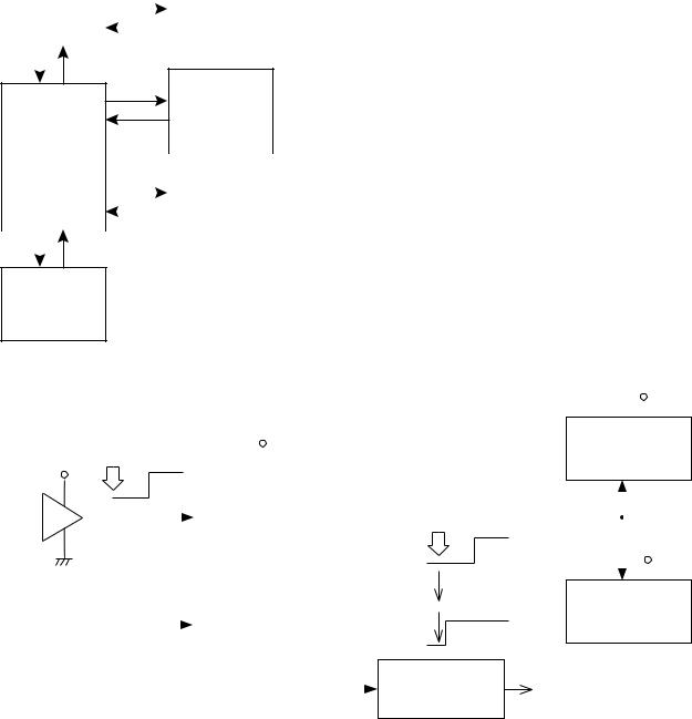
MEMORY DEVICES
Each memory device has the following data.
|
CPU |
|
|
|
|
|||
Internal Memory |
|
|
|
|
||||
|
|
|
|
|
|
|
|
|
2 |
ROM |
512 kbit |
|
|
|
|
RAM1 |
|
|
|
|
|
|
|
|
|
|
3 |
RAM |
16 kbit |
|
|||||
|
|
|
|
1 |
||||
|
|
|
|
|
|
|
|
|
|
|
|
|
|
||||
|
LSI9 |
|
|
|
1 Mbit |
|||
|
|
|
|
|||||
|
|
|
|
|
|
|
|
LSI8 |
|
|
|
|
|
||||
|
|
|
|
|
|
|
|
|
|
|
|
|
|
|
|
|
|
ROM1
4
8 Mbit
LSI2
DSP |
|
|
|
|
||
|
|
|
|
|||
|
|
|
|
|
|
ROM2 |
|
|
|
|
|
|
5 |
|
|
|
|
|
|
|
LSI4 |
|
|
|
32 Mbit |
||
|
|
|
||||
|
|
|
|
|
|
LSI3 |
|
|
|
||||
|
|
|
|
|
|
|
|
|
|
|
|
|
|
Working RAM
6
256 kbit LSI5
1RAM1 :
S-RAM for operation program, Register, Pattern and Song. (Upper part of data bus)
2Internal ROM of CPU :
Main program data for system operation
3Internal RAM of CPU :
Work area for system operation
4ROM1 :
Demo, Accompaniment data, Song, Pattern, Synth mode
5ROM2 :
Sound Waveforms/Tone data Digital sound effect
6Working RAM : Work area for DSP
RESET CIRCUIT |
|
|
|
|
|
|
|
|
|
|
|
|
|
|
DVDD |
|||||
|
|
|
|
|
|
|
|
|
|
|
|
|
||||||||
|
|
|
|
|
|
|
|
|
|
|
|
|
|
|
|
|
DSP |
|||
|
|
Battery set |
|
VDD |
|
|
|
|
|
|
|
|
|
HG51B155FD |
||||||
VDD |
|
|
|
|
|
|
|
|
|
|
|
LSI4 |
||||||||
|
|
|
|
|
|
|
|
|
|
|
|
|
|
|
|
|
RESB |
|||
|
|
|
|
|
|
|
|
|
|
|
|
|
|
|
|
|
|
|
|
|
|
|
RESET |
|
|
|
|
|
RESET |
|
|
|
|
|
|
|
|
|
|||
|
|
RES |
|
PB0 |
|
|
|
|
|
|
|
|
|
|||||||
|
|
|
|
|
|
|
|
|
|
PW/SW ON |
|
|
|
|
||||||
|
|
|
|
|
|
|
|
|
|
|
|
|
|
|
|
|
|
|||
|
|
|
|
|
|
|
|
|
|
|
|
|
|
|
|
|
|
|
|
|
|
|
|
|
|
|
CPU |
|
|
|
|
RESET |
|
|
|
DVDD |
|||||
|
|
|
HD6473042F16-463 |
|
|
|
|
|
|
|
|
|
|
|
|
|||||
|
|
|
|
|
|
|
|
|
|
|
|
|
|
|
|
|||||
|
|
|
|
|
|
LSI9 |
|
|
|
|
APO |
|
RESB |
|||||||
|
|
|
|
|
|
|
|
|
|
|
|
|
Key Controller |
|||||||
|
|
PWSW |
|
|
|
|
|
APO |
|
|
|
|
|
|||||||
|
|
|
|
|
|
|
|
|
|
|
|
|||||||||
|
|
NMI |
|
PA7 |
DVDD |
TC190C020AF-001 |
||||||||||||||
|
|
|
|
|
|
|
|
|||||||||||||
|
|
|
|
|
|
|
|
LSI10 |
||||||||||||
From power switch |
|
|
|
|
|
|
|
|
|
(5V) |
||||||||||
|
|
|
|
|
|
|
|
|
|
|
|
|
||||||||
|
|
|
|
|
|
|
|
|
|
|
|
|
Power Supply |
DVDD |
||||||
|
|
|
|
|
|
|
|
|
|
|
|
|
||||||||
|
|
|
|
|
|
|
|
|
|
|
|
|
|
Circuit |
||||||
|
|
|
|
|
|
|
|
|
|
|
|
|
|
|
|
|
|
|||
Initial reset
When batteries are set or an AC adapter is connected, the reset IC provides a low pulse to the CPU. When the power switch is pressed, the CPU receives a low pulse of POWER signal. The CPU first raises APO signal to +5 V to generate DVDD voltage, then raises RESET signal to +5 V. During this period the DSP and the key controller LSI initialize their internal circuits.
— 9 —
POWER SUPPLY CIRCUIT
The power supply circuit provides various voltages as shown below.
The voltage VDD (+5 V) is provided as long as batteries or AC adaptor is set. Other voltages are controlled by APO (Auto Power Off) signal from CPU.
|
|
PW/ON |
|
|
NMI |
|
|
|
APO |
|
CPU |
|
|
APO |
HD6473042F16-463 |
|
|
PA7 |
|
|
|
|
|
|
|
|
LSI9 |
From |
+9V ~ +12V |
|
NMI |
Batteries or |
|
|
PW/SW |
AC Adaptor |
|
|
|
|
|
|
Power Supply
— 10 —
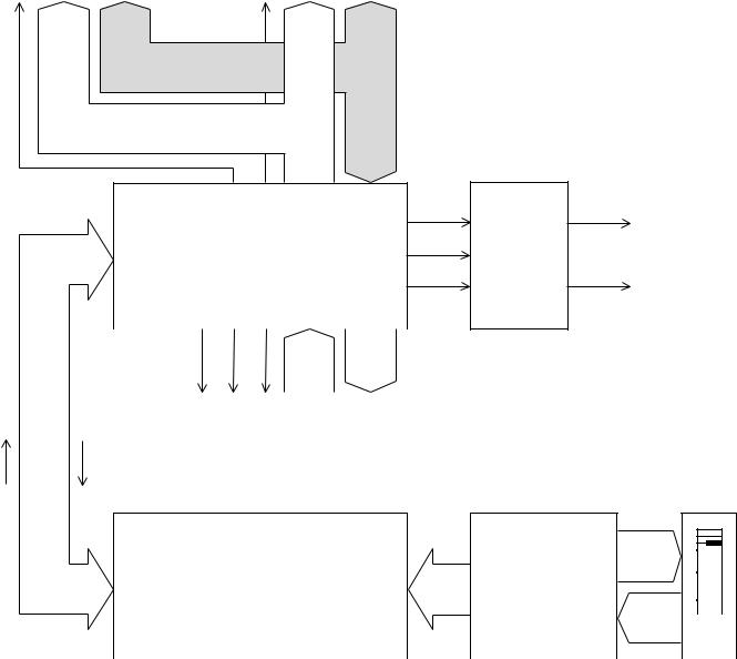
DSP and DAC CIRCUIT
The DSP (Digital Signal Processor) and DAC (Digital Analog Converter) consists of the following circuits.
ROM1 |
|
ROM2 |
MSM27CB02CZ-463 |
|
MX23C3210MC-12CA89 |
LSI2 (8Mbit) |
|
LSI3 (32Mbit) |
CE A0 ~ A18 Q0 ~ Q15 |
|
CE A0 ~ A20 Q0 ~ Q15 |
RA23 |
RA0 ~ |
RA22 |
RA0 ~ |
|
|
||
|
RA18 |
|
RA20 |
RD0 ~ RD15
RA0 ~ RA20
DSP
HG51B155FD
LSI4
SOLP: Sound data BOK: Bit clock WOK1: Word clock
DAC
SOLP
SI
BOK CLK
WOK1 LRCK
UPD6376GS
ROUT
LOUT
|
|
|
|
|
|
CS |
OE WE |
ED0 ~ |
EA0 ~ |
|
|
|
|
|
|
|
PG |
ED15 |
EA14 |
|
|
|
|||||
|
|
|
|
|
|
|
|
||||||
|
|
|
|
|
|
|
|
|
|
|
|
|
|
|
D8 ~ |
24.576 MHz |
|
|
D0 ~ D15 |
A0 ~ A14 |
|
|
|
||||
|
|
|
|
|
|
|
|
||||||
|
|
|
|
|
|
|
Working RAM (256K-bit) |
|
|
|
|||
|
D15 |
|
|
|
|
|
|
|
|
|
|||
|
|
|
|
|
|
|
TC55257DFL-70L |
|
|
|
|||
key |
|
Control |
|
|
|
|
|||||||
|
|
|
LSI5 |
|
|
|
|
||||||
data |
|
data |
|
|
|
|
|
|
|||||
|
|
|
|
|
|
|
|
||||||
|
|
|
|
|
|
|
|
|
|
|
|
|
|
|
|
|
|
|
|
|
|
|
|
|
|
|
|
CPU |
|
Key Controller |
KC0 ~ |
|
|
|
|
|
|
|
|
|
|
|
|||
D0 ~ |
KC7 |
|
|
|
|
|
||
HD6473042F16-463 |
TC190C020AF-001 |
|
|
|
|
|
||
|
|
|
|
|
|
|||
|
|
|
|
|
|
|||
D15 |
SI0 ~ SI7 |
|
|
|
|
|
||
LSI9 |
LSI10 |
|
|
|
|
|
||
|
|
|
|
|
||||
|
|
|
|
|
|
|||
|
|
|
|
|
|
|||
|
FI0 ~ FI7 |
Key- |
||||||
|
key |
|
||||||
|
|
|
board |
|||||
|
data |
|
|
|||||
|
|
|
|
|
|
|
|
|
|
|
|
|
|
|
|
|
|
— 11 —
 Loading...