


R
(with price)
CTK-750
CTK-750
ELECTRONIC KEYBOARD
CONTENTS
Specifications . . . . . . . . . . . . . . . . . . . . . . . . . . . . . . . . . . . . . . . . . . 1
Replacing the DSP (HG51A115A01FD) . . . . . . . . . . . . . . . . . . . . . 2
Block Diagram . . . . . . . . . . . . . . . . . . . . . . . . . . . . . . . . . . . . . . . . . 3
Circuit Description . . . . . . . . . . . . . . . . . . . . . . . . . . . . . . . . . . . . . 4
Wiring Diagram . . . . . . . . . . . . . . . . . . . . . . . . . . . . . . . . . . . . . . . 13
Major Waveforms . . . . . . . . . . . . . . . . . . . . . . . . . . . . . . . . . . . . . . 14
PCB View and Major Check Points . . . . . . . . . . . . . . . . . . . . . . . 16
Schematic Diagrams . . . . . . . . . . . . . . . . . . . . . . . . . . . . . . . . . . 17
Exploded View . . . . . . . . . . . . . . . . . . . . . . . . . . . . . . . . . . . . . . . . 20
IC and Transistor Lead Identification . . . . . . . . . . . . . . . . . . . . . 21
Parts List . . . . . . . . . . . . . . . . . . . . . . . . . . . . . . . . . . . . . . . . . . . 23
— 14 —
SPECIFICATIONS
General
Number of Keys: |
61 |
|
|
|
|
Polyphonic: |
32-note |
|
|
|
|
Preset Tones: |
128 |
|
|
|
|
|
Tone Expander: Layer, Split |
|
|
||
Keyboard Controls: |
Touch Response: On/Off |
|
|
||
|
Touch Sensitivity: Light/Middle/Heavy |
|
|||
Key Transpose: |
Range from F# to F by |
a half-note increment |
|
||
Auto-Rhythms: |
128 |
|
|
|
|
|
Tempo Control: 40 to 255 |
|
|
||
Auto-Accompaniment: |
CASIO Chord/Fingered/Full-Range Chord |
|
|||
|
Controller: Variation, Fill-In, Intro/Ending |
|
|||
Magical Preset Variations: |
128; |
BREAK BEAT |
16 |
MELODYCOMP |
8 |
|
|
SHADOW DRUM |
4 |
FREE SESSION |
32 |
|
|
TONE STACK |
40 |
KEY SPLIT |
12 |
|
|
HYPERACTIVE |
16 |
|
|
Digital Effects: |
16; Reverb-1, Reverb-2, Reverb-3, Chorus, Tremplp, Phase Shifter, |
||||
|
|
Organ SP, Enhancer, Flanger, EQ Loudness, Delay-1, Delay-2, |
|||
|
|
Analog Delay, Tap Delay, Chorus Reverb, Tremolo Reverb |
|||
Sound/Control Pads: |
6 |
|
|
|
|
Pad Variations: |
32; Phrases: 10, Drums: 10, SE/Percussion: 10, Controller: 2 |
||||
Song Memories: |
2; |
Tracks: 6 |
|
|
|
|
|
System: Real-time recording |
|
||
|
|
Memory Capacity: Approx. 5,800 notes |
|
||
Registration Memories: |
10 |
|
|
|
|
Registration Items: |
Tone Number, Rhythm Number, Tempo, Accompaniment Mode, |
||||
|
Accompaniment Volume, Effects, Layer On/Off, Split On/Off, |
||||
|
Pad Variation, Assignable Jack, Auto-Accompaniment On/Off, |
||||
|
Auto-Accompaniment Controller, MIDI (Channel On/Off, GM On/Off, |
||||
|
Local Control On/Off, Bend Range) |
|
|||
Tuning Control: |
440Hz ± 100 cents |
|
|
|
|
Terminals: |
Headphone Jack [Output Impedance: 100 Ω, Output Voltage: 1.7 V(rms) |
||||
|
MAX], Assignable Jack, MIDI Jacks (IN, OUT), AC Adaptor Jack (12V) |
||||
Built-In Speakers: |
12 cm dia. 1.1W Input Rating: 2 pcs. |
|
|||
Power Source: |
2-way AC or DC source |
|
|
|
|
|
AC: AC adaptor AD-12 |
|
|
|
|
|
DC: 6 D size dry batteries |
|
|
||
|
Battery life: Approx. 5 hours by |
manganese batteries R20P(SUM-1) |
|||
|
|
Approx. 5 hours by alkaline batteries LR20(AM1) |
|||
Auto Power Off: |
Approximately 6 minutes after the last operation |
|
|||
Power Consumption: |
18 W |
|
|
|
|
Dimentions: |
141 x 968 x 411 mm (HWD) |
|
|
||
|
(5-11/16 x 38-1/16 x 16-5/16 inches) (HWD) |
|
|||
Weight: |
7.0 kg (15.5 lbs) excluding batteries |
|
|||
Standard Accessory: |
Music stand |
|
|
|
|
— 1 —

Electrical
Current Drain with 12V DC: |
390 mA ± 20% |
No Sound Output |
|
Maximum Volume |
1700 mA ± 20% |
with white keys D2 to D3 pressed in Synth-Bass-2 tone |
|
and in Latin Fusion rhythm at initial setup tempo |
|
Volume; maximum, Touch: maximum |
|
Line Output Level (Vrms with 47 KΩ load each cannel): |
|
with key D4 pressed in FSynth-Bass-2 tone on L-ch |
850 mV ± 20% |
with key G4 pressed in FSynth-Bass-2 tone on R-ch |
800 mV ± 20% |
Phone Output Level (Vrms with 8 Ω load each channel): |
280 mV ± 20% |
with key D4 pressed in FSynth-Bass-2 tone on L-ch |
|
with key G4 pressed in FSynth-Bass-2 tone on R-ch |
260 mV ± 20% |
Speaker Input Level: |
5200 mV ± 20% |
with key D4 pressed in FSynth-Bass-2 tone on L-ch |
|
with key G4 pressed in FSynth-Bass-2 tone on R-ch |
5600 mV ± 20% |
Minimum Operating Voltage: |
5.5 V |
REPLACING THE DSP (HG51A115A01FD)
Note: To increase productivity ,the DSP HG51A115A01FD is sticked on the main PCB with a double-side adhesive tape, then its leads are soldered.
Remove the DSP according to the following procedures.
1.Prepare isopropyl alcohol and a flat IC desoldering machine (Spot Heater HS-600).
2.Apply plenty of the alcohol to the adhesive tape from the reverse side of the main PCB. (Fig. 1) There is a hole on the PCB just under the LSI, and the adhesive tape can be seen through the hole.
3.Leave it more than one minute so that the alcohol weaken adhesive power fully.
4.Using a proper size of nozzle, apply heat to leads of the LSI with the desoldering machine.
5.Grasp the LSI with tweezers, and using gentle force vibrate the tweezers to feel melting solder. (Fig.2)
6.Remove the LSI after meltingsolder at every leads wholly.
 Spot Heater HS-600
Alcohl
HG51A115A
LSI
- S
Fig.1 |
Fig.2 |
— 2 —

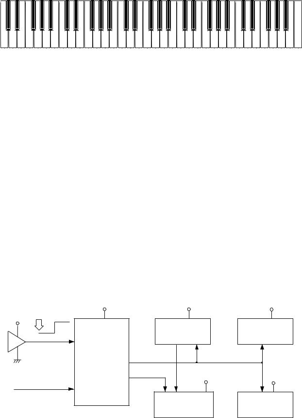
BLOCK DIAGRAM
Keyboard
FI0 ~ FI7 |
KC0 ~ |
|
SI0 ~ SI7 |
||
KC7 |
Key Touch LSI
HG52E35P
A0 ~ A2
Working Strage
RAM (256K-bit)
HM62256ALP-10
A0 ~ A14
|
7-Segment |
LEDs |
|
|
LED |
LO0 ~ LO4 |
|
|
|
|
|
|
|
LED driver |
|
|
|
BA612 |
|
Gate Array |
|
KO0 ~ KO7 |
|
UPD65005C-578 |
|
|
|
|
|
LD0 ~ LD7 |
|
|
|
|
Buttons |
D0~D7 |
|
CPU |
KI1 ~ KI7 |
|
|
|
|
|
HD6433298A18P |
VDD |
|
|
|
||
A0 ~ A15 |
|
|
POWER |
Power Switch
OUT IN
MIDI
APO
A0 ~ A3
|
EA0 ~ EA14 |
DSP |
RA0 ~ RA19 |
Sound Source ROM |
||
Effect RAM |
|
|||||
|
|
|
|
(16M-bit) |
||
(256K-bit) |
HG51A115A01FD |
|
|
|||
|
TC5316200CP-C081 |
|||||
HM62256ALP-10 |
|
|||||
ED0 ~ ED7 |
|
RD0 ~ RD15 |
|
|
||
|
|
|
|
|||
|
|
|
|
|
||
|
WCK1 |
SLOP |
BCK |
|
|
|
|
D/A Converter |
|
|
|
|
|
|
UPD6376CX |
|
|
|
|
|
|
|
|
VD |
LVDD |
DVDD |
|
|
Filter |
Filter |
|
VCC |
AVDD |
VDD |
|
|
|
|
|
||
|
Output |
|
|
|
|
|
Speakers |
|
Main |
|
Power Supply Circuit |
||
Volume |
|
|||||
|
|
|
Q1 ~ Q7 |
|
||
|
|
|
|
|
|
|
|
Power Amplifier |
|
|
|
|
|
|
LA4620 |
|
|
|
|
|
— 3 —

CIRCUIT DESCRIPTION
Key Matrix
|
KC0 |
KC1 |
KC2 |
KC3 |
KC4 |
KC5 |
KC6 |
KC7 |
||||||||
FI0 |
C2 |
1 |
C#2 |
1 |
D2 |
1 |
D#2 |
1 |
E2 |
1 |
F2 |
1 |
F#2 |
1 |
G2 |
1 |
SI0 |
C2 |
2 |
C#2 |
2 |
D2 |
2 |
D#2 |
2 |
E2 |
2 |
F2 |
2 |
F#2 |
2 |
G2 |
2 |
FI1 |
G#2 |
1 |
A2 |
1 |
A#2 |
1 |
B2 |
1 |
C3 |
1 |
C#3 |
1 |
D3 1 |
D#3 |
1 |
|
SI1 |
G#2 |
2 |
A2 |
2 |
A#2 |
2 |
B2 |
2 |
C3 2 |
C#3 |
2 |
D3 |
2 |
D#3 |
2 |
|
FI2 |
E3 |
1 |
F3 |
1 |
F#3 |
1 |
G3 |
1 |
G#3 |
1 |
A3 |
1 |
A#3 |
1 |
B3 |
1 |
SI2 |
E3 |
2 |
F3 |
2 |
F#3 |
2 |
G3 |
2 |
G#3 |
2 |
A3 |
2 |
A#3 |
2 |
B3 |
2 |
FI3 |
C4 |
1 |
C#4 |
1 |
D4 |
1 |
D#4 |
1 |
E4 |
1 |
F4 |
1 |
F#4 |
1 |
G4 |
1 |
SI3 |
C4 |
2 |
C#4 |
2 |
D4 |
2 |
D#4 |
2 |
E4 |
2 |
F4 |
2 |
F#4 |
2 |
G4 |
2 |
FI4 |
G#4 |
1 |
A4 |
1 |
A#4 |
1 |
B4 |
1 |
C5 |
1 |
C#5 |
1 |
D5 |
1 |
D#5 |
1 |
SI4 |
G#4 |
2 |
A4 |
2 |
A#4 |
2 |
B4 |
2 |
C5 |
2 |
C#5 |
2 |
D5 |
2 |
D#5 |
2 |
FI5 |
E5 |
1 |
F5 |
1 |
F#5 |
1 |
G5 |
1 |
G#5 |
1 |
A5 |
1 |
A#5 |
1 |
B5 |
1 |
SI5 |
E5 |
2 |
F5 |
2 |
F#5 |
2 |
G5 |
2 |
G#5 |
2 |
A5 |
2 |
A#5 |
2 |
B5 |
2 |
FI6 |
C6 |
1 |
C#6 |
1 |
D6 |
1 |
D#6 |
1 |
E6 |
1 |
F6 |
1 |
F#6 |
1 |
G6 |
1 |
SI6 |
C6 |
2 |
C#6 |
2 |
D6 |
2 |
D#6 |
2 |
E6 |
2 |
F6 |
2 |
F#6 |
2 |
G6 |
2 |
FI7 |
G#6 |
1 |
A6 |
1 |
A#6 |
1 |
B6 |
1 |
C7 |
1 |
|
|
|
|
|
|
SI7 |
G#6 |
2 |
A6 |
2 |
A#6 |
2 |
B6 |
2 |
C7 |
2 |
|
|
|
|
|
|
Note: Each key has two contacts, the first conatct 1 and second contact 2 .
Key
|
FI |
Second contact 2 |
First contact 1 |
|
KC |
|
SI |
— 4 —
Nomenclature of Keys
C#2 D#2 |
F#2 G#2 A#2 |
C#3 D#3 |
F#3 G#3 A#3 |
C#4 D#4 |
F#4 G#4 A#4 |
C#5 D#5 |
F#5 G#5 A#5 |
C#6 D#6 |
F#6 G#6 A#6 |
C2 |
D2 |
E2 |
F2 |
G2 |
A2 |
B2 |
C3 |
D3 |
E3 |
F3 |
G3 |
A3 |
B3 |
C4 |
D4 |
E4 |
F4 |
G4 |
A4 |
B4 |
C5 |
D5 |
E5 |
F5 |
G5 |
A5 |
B5 |
C6 |
D6 |
E6 |
F6 |
G6 |
A6 |
B6 |
C7 |
|||||
Button Matrix |
|
|
|
|
|
|
|
|
|
|
|
|
|
|
|
|
|
|
|
|
|
|
|
|
|
|
|
|
|
|
|
|
|
|
||||||
|
|
|
|
|
|
|
|
|
|
|
|
|
|
|
|
|
|
|
|
|
|
|
|
|
|
|
|
|
|
|
|
|
|
|
|
|
||||
|
|
|
|
|
|
|
KI1 |
|
|
|
KI2 |
|
|
|
|
KI3 |
|
|
|
KI4 |
|
|
|
KI5 |
|
|
|
|
KI6 |
|
|
|
KI7 |
|
|
|
||||
|
|
|
|
|
|
|
|
|
|
|
|
|
|
|
|
|
|
|
|
|
|
|
|
|
|
|
|
|||||||||||||
|
|
KO0 |
|
|
|
Split |
|
|
Layer |
|
|
Upper 1 |
|
Lower 1 |
|
|
Lower 2 |
|
|
Upper 2 |
|
|
|
|
|
|
|
|||||||||||||
|
|
|
|
|
|
|
|
|
|
|
|
|
|
|
|
|
|
|
|
|
|
|
|
|
|
|
||||||||||||||
|
|
KO1 |
|
|
Transpose |
|
Tune |
|
|
|
|
MIDI |
|
|
Jack |
|
|
Rhythm |
|
|
|
Tone |
|
Play Style |
|
|
||||||||||||||
|
|
|
|
|
|
|
|
|
|
|
|
|
|
|
|
|
|
|
|
|
|
|
|
|
|
|
|
|
|
|||||||||||
|
|
KO2 |
|
|
|
|
|
|
|
|
|
|
|
|
Track 4 |
|
Track 5 |
|
|
Track 6 |
|
|
Track 2 |
|
|
Track 3 |
|
|
||||||||||||
|
|
|
|
|
|
|
|
|
|
|
|
|
|
Chord 1 |
|
Chord 2 |
|
|
Chord 3 |
|
|
Rhythm |
|
|
Bass |
|
|
|
||||||||||||
|
|
|
|
|
|
|
|
|
|
|
|
|
|
|
|
|
|
|
|
|
|
|
|
|
|
|||||||||||||||
|
|
|
|
|
|
|
|
|
|
|
|
|
|
|
|
|
|
|
|
|
|
|
|
|
|
|
|
|
|
|
|
|
|
|
|
|
|
|||
|
|
KO3 |
|
|
|
3 |
|
|
|
|
6 |
|
|
|
|
9 |
|
|
|
Demo |
|
|
Touch |
|
|
|
Digital |
|
Resistration |
|
||||||||||
|
|
|
|
|
|
|
|
|
|
|
|
|
|
|
|
|
Responce |
|
|
Effect |
|
|
||||||||||||||||||
|
|
|
|
|
|
|
|
|
|
|
|
|
|
|
|
|
|
|
|
|
|
|
|
|
|
|
|
|
|
|
|
|
|
|||||||
|
|
|
|
|
|
|
|
|
|
|
|
|
|
|
|
|
|
|
|
|
|
|
|
|
|
|
|
|
|
|
|
|
|
|
|
|
|
|||
|
|
KO4 |
|
|
|
2 |
|
|
|
|
5 |
|
|
|
|
8 |
|
|
|
Track 1 |
|
|
|
1 |
|
|
|
|
4 |
|
|
|
|
7 |
|
|
|
|||
|
|
|
|
|
|
|
|
|
|
|
|
|
|
|
|
|
|
|
|
|
|
|
|
|
|
|
|
|
|
|
|
|
|
|
|
|||||
|
|
KO5 |
|
|
Accomp. |
|
Song |
|
|
Accomp. |
|
Track |
|
|
|
0 |
|
|
|
|
- |
|
|
|
|
+ |
|
|
|
|||||||||||
|
|
|
|
Volume |
|
|
Memory |
|
|
|
|
|
|
|
|
|
|
|
|
|
|
|
|
|
||||||||||||||||
|
|
|
|
|
|
|
|
|
|
|
|
|
|
|
|
|
|
|
|
|
|
|
|
|
|
|
|
|
|
|
|
|
|
|
||||||
|
|
|
|
|
|
|
|
|
|
|
|
|
|
|
|
|
|
|
|
|
|
|
|
|
|
|
|
|
|
|
|
|
||||||||
|
|
KO6 |
|
|
Synchro/ |
|
Variation |
|
|
Normal/ |
|
Intro |
|
|
|
F |
|
|
|
|
D |
|
|
|
|
B |
|
|
|
|||||||||||
|
|
|
|
Ending |
|
|
/Fill-In |
|
|
|
Fill-In |
|
|
|
|
|
|
|
|
|
|
|
|
|
|
|
|
|||||||||||||
|
|
|
|
|
|
|
|
|
|
|
|
|
|
|
|
|
|
|
|
|
|
|
|
|
|
|
|
|
|
|
|
|
||||||||
|
|
|
|
|
|
|
|
|
|
|
|
|
|
|
|
|
|
|
|
|
|
|
|
|
|
|
|
|
|
|
|
|
|
|
|
|||||
|
|
KO7 |
|
|
|
Mode |
|
|
|
A |
|
|
|
|
C |
|
|
|
|
E |
|
|
|
Start/ |
|
|
|
Tempo |
|
|
Tempo |
|
|
|||||||
|
|
|
|
|
|
|
|
|
|
|
|
|
|
|
|
|
|
|
Stop |
|
|
|
Down |
|
|
Up |
|
|
|
|||||||||||
|
|
|
|
|
|
|
|
|
|
|
|
|
|
|
|
|
|
|
|
|
|
|
|
|
|
|
|
|
|
|
|
|
|
|||||||
|
|
|
|
|
|
|
|
|
|
|
|
|
|
|
|
|
|
|
|
|
|
|
|
|
|
|
|
|
|
|
|
|
|
|
|
|
|
|
|
|
Reset Circuit |
|
|
|
|
|
Battery set |
VDD |
|
VDD |
|
DVDD |
VDD |
|
|
|
|
|
|
|
|
Gate Array |
|
DSP |
RESET |
|
|
UPD65005C-578 |
|
HG51A115A01FD |
|
|
|
|
|
|
Reset IC |
CPU |
|
|
|
|
S8053ANO |
-RESET |
|
|
|
|
HD6433298A18P |
|
|
|
||
POWER |
|
WR |
-SRAM |
VDD |
DVDD |
|
|
|
|
|
|
From power switch |
|
|
Working Strage RAM |
Key Touch LSI |
|
|
|
|
|||
|
|
|
HM62256ALP-10 |
|
HG52E35 |
— 5 —
Initial reset
When batteries are set or an AC adapter is connected, the reset IC provides a low pulse to the CPU. The CPU then initializes its internal circuit and clears data in the working strage RAM.
Power ON reset
When the power switch is pressed, the CPU receives a low pulse of POWER signal. The CPU first raises APO signal to +5V to generat DVDD voltage, then raises RESET signal to +5V. During this period the gate array, the DSP and the key touch LSI initializes their internal circuit.
CPU (HD6433298A18P)
The 16-bit CPU contains a 32k-bit ROM, a 1k-bit RAM, seven 8-bit I/O ports, an A/D convertor and serial interfaces. The CPU accesses to the working strage RAM, the DSP and the key touch LSI. The CPU also controls buttons, LEDs, bender input and MIDI input/output.
Pin No. |
Terminal |
In/Out |
Function |
|
|
|
|
1 |
P40 |
Out |
KO signal data output |
|
|
|
|
2 |
P41 |
Out |
Clock for KO signal data |
|
|
|
|
3 |
P42 |
Out |
APO (Auto Power Off) signal output. ON: High, OFF: Low |
|
|
|
|
4 |
P43 |
Out |
Read enable signal output |
|
|
|
|
5 |
P44 |
Out |
Write enable signal output |
|
|
|
|
6 |
P45 |
|
Not used. |
|
|
|
|
7 |
P46 |
Out |
10MHz clock output |
|
|
|
|
8 |
P47 |
In |
Wait signal input. Connected to +5V. |
|
|
|
|
9 |
TXD |
Out |
MIDI signal output |
|
|
|
|
10 |
RXD |
In |
MIDI signal input |
|
|
|
|
11 |
P52 |
Out |
Reset signal output |
|
|
|
|
12 |
-RESET |
In |
Reset signal input |
|
|
|
|
13 |
-NMI |
In |
Power ON signal input. |
|
|
|
|
14 |
VCC |
In |
+5V source |
|
|
|
|
15 |
-STBY |
In |
Standby signal input. Connected to +5V. |
|
|
|
|
16 |
VSS |
In |
Ground (0V) source |
|
|
|
|
17 |
XTAL |
In |
20MHz clock input |
|
|
|
|
18 |
EXTAL |
In |
20MHz clock input |
|
|
|
|
19, 20 |
MD1, MD0 |
In |
Mode selection input. (Internal ROM mode --- MD1: Hight, MD0: Low) |
|
|
|
|
21 |
AVSS |
In |
Ground (0V) source for internal DAC |
|
|
|
|
22 |
AN0 |
In |
Analog input. Connected to the bender volume. |
|
|
|
|
23 ~ 29 |
P71 ~ P77 |
In |
Button input signal input |
|
|
|
|
30 |
AVCC |
In |
+5V source for internal DAC |
|
|
|
|
31 ~ 38 |
P60 ~ P67 |
Out |
LED segment signal output |
|
|
|
|
39 |
VCC |
In |
+5V source |
|
|
|
|
40 ~ 56 |
P27 ~ P10 |
Out |
Address bus |
|
|
|
|
48 |
VSS |
In |
Ground (0V) source |
|
|
|
|
57 ~ 64 |
P30 ~ P37 |
Ijn/Out |
Data bus |
|
|
|
|
— 6 —
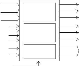
Gate Array (UPD65005C-578)
Functions of the gate array are;
(1)To decode chip select signals for the working strage RAM, the DSP and the key touch LSI.
(2)To hold the following signals on "Low" during power off.
Read/write enable signals for the DSP and the key touch LSI 10MHz clock for the key touch LSI
(3) To generate button scan / LED drive signals.
The following table shows the pin functions of the gate array.
Pin No. |
Terminal |
In/Out |
Function |
|
|
|
|
1 |
-RESET |
In |
Reset signal input |
|
|
|
|
2 |
-RDAPO |
Out |
Read enable signal output |
|
|
|
|
3 |
-WRAPO |
Out |
Write enable signal output |
|
|
|
|
4 |
-LSIS |
Out |
Chip select signal for the DSP |
|
|
|
|
5 |
-HG |
Out |
Chip select signal for the key touch LSI |
|
|
|
|
6 |
PHAPO |
Out |
10MHz clock for the key touch LSI |
|
|
|
|
7 |
-SRAM |
Out |
Chip select signal for the working strage RAM |
|
|
|
|
8 ~ 9 |
KO8 ~ KO9 |
|
Not used. |
|
|
|
|
10 ~ 17 |
KO7 ~ KO0 |
Out |
Button scan / LED drive signal output |
|
|
|
|
18 ~ 20 |
|
|
Not used. |
|
|
|
|
21 |
GND |
In |
Ground (0V) source |
|
|
|
|
22 |
PHA |
In |
10MHz clock input |
|
|
|
|
23 |
-WR |
In |
Write enable signal input |
|
|
|
|
24 |
-RD |
In |
Read enable signal input |
|
|
|
|
25 |
-APO |
In |
APO (Auto Power Off) signal input |
|
|
|
|
26 |
KOC |
In |
KO signal data input |
|
|
|
|
27 |
KOD |
In |
Clock for KO signal data |
|
|
|
|
28 ~ 39 |
A15 ~ A4 |
In |
Address bus |
|
|
|
|
40, 41 |
D0, D1 |
In |
Data bus |
|
|
|
|
42 |
VDD |
In |
+5V source |
|
|
|
|
LSIS
A4 ~ A15
Address decoder HG
SRAM
D0, D1
RD |
|
RDAPO |
|
|
WRAPO |
||
WR |
Controller |
||
|
|||
PHA |
|
||
|
PHAPO |
||
APO |
|
|
|
KOD |
Shift register |
KO0 ~ KO7 |
|
KOC |
|||
|
|
(Chip select sigal for the DSP)
(Chip select signal for the key touch LSI)
(Chip select signal for the working strage RAM)
(Read enable signal controlled by APO)
(Write enable signal controlled by APO)
(10MHz clock for the key touchLSI. Controlled by APO)
(Button scan / LED drive signal)
RESET
— 7 —
 Loading...