


CTK-431
|
|
|
PHONES/ |
DC 9V |
IN |
OUT |
|
|
|
|
|
|
|
|
|
|
|
|
OUTPUT |
|
|
MIDI |
|
|
|
|
|
|
|
|
|
|
|
|
|
|
|
|
|
|
TONE |
|
|
|
|
|
|
|
|
|
|
|
|
|
|
|
RHYTHM |
|
|
|
|
|
|
|
|
|
|
|
|
|
|
|
SONG BANK |
|
|
|
|
|
|
|
|
|
|
|
|
|
|
|
STATUS |
|
|
|
|
|
|
|
|
|
|
|
|
|
|
|
TEMPO |
|
|
|
|
|
|
|
|
|
|
|
|
|
|
|
MAIN VOLUME |
|
|
|
|
|
|
|
|
|
|
|
|
|
|
|
|
|
MUSICAL INFORMATION SYSTEM |
|
|
|
|
POWER/MODE |
MAIN |
SYNCHRO/ START/ |
|
|
|
|
|
|
|
|
|
SONG BANK CONTROLLER |
|||
|
|
VOLUME |
FILL-IN STOP |
TEMPO |
CHORD BOOK |
M |
m |
7 |
M7 |
dim |
TONE |
SONG BANK |
REW |
STOP |
FF |
|
FINGERED |
|
|
|
|
0 |
1 |
2 |
3 |
4 |
|
LEFT |
|
|
RIGHT |
ON |
CASIO CHORD |
|
|
|
|
|
|
|
|||||||
|
|
|
|
|
|
|
|
|
|
ON/OFF |
|
|
ON/OFF |
||
|
NORMAL |
|
|
|
|
|
|
|
|
|
|
|
|
|
|
100 SONG BANK KEYBOARD |
OFF |
5 |
6 |
7 |
8 |
9 |
|
|
MUSICAL INFORMATION SYSTEM |
|
|
|
|||||
SONG BANK CONTROLLER |
ACCOMP VOLUME |
aug |
sus4 |
-5 |
add9 |
CLEAR |
RHYTHM |
TRANSPOSE/ |
|
TUNE/MIDI
PLAY
/PAUSE
CTK-431
INDEX |
ELECTRONIC KEYBOARD |
|
|
CONTENTS
Specifications ................................................................................................................................... |
1 |
Block Diagram .................................................................................................................................. |
2 |
Circuit Description ............................................................................................................................ |
3 |
Adjustment ....................................................................................................................................... |
7 |
Major Waveforms ............................................................................................................................. |
8 |
Printed Circuit Boards ...................................................................................................................... |
9 |
Schematic Diagrams ...................................................................................................................... |
10 |
Exploded View ............................................................................................................................... |
14 |
Parts List ........................................................................................................................................ |
15 |

|
|
|
SPECIFICATIONS |
GENERAL |
|
|
|
Keyboard: |
49 standard-size keys, 4 octaves |
||
Tones: |
100 |
|
|
Polyphony: |
12 notes maximum (6 for certain tones) |
||
Auto accompaniment |
|
|
|
Rhythm patterns: |
100 |
|
|
Tempo: |
Variable (236 steps, = 20 to 255) |
||
Chords: |
2 fingering methods (CASIO CHORD, FINGERED) |
||
Rhythm controller: |
START/STOP, SYNCHRO/FILL-IN |
||
Accomp volume: |
0 to 9 (10 steps) |
||
Song bank |
|
|
|
Tunes: |
100 |
|
|
Controllers: |
PLAY/PAUSE, STOP, REW, FF, LEFT ON/OFF, RIGHT ON/OFF |
||
Musical dictionary |
|
|
|
Name display: |
TONE, RHYTHM, SONG BANK name/number, keyboard settings name/value |
||
Tempo: |
Tempo value, metronome, synchro standby, beat indicator |
||
Chord: |
Chord name, Chord form |
||
Fingering: |
Fingering indicators, parts, pedal (The pedal indicator is for received MIDI |
||
|
data only.) |
||
Song bank status: |
PLAY, PAUSE, REW, FF |
||
Staff: |
4 octaves with sharp and flat indications |
||
Keyboard: |
4 octaves |
||
MIDI: |
5 multi-timbre receive |
||
Other functions |
|
|
|
Transpose: |
12 steps (–6 semitones to +5 semitones) |
||
Tuning: |
Variable (A4 = approximately 440 Hz ± 50 cents) |
||
Volume: |
0 to 9 (10 steps) |
||
Terminals |
|
|
|
MIDI terminals: |
IN, OUT |
||
Phones/Output terminal: |
Stereo standard jack (Output is monaural.) |
||
|
Output Impedance: 60 Ω |
||
|
Output Voltage: 5 V (RMS) MAX |
||
Power supply terminal: |
9 V DC |
||
Power supply |
Dual power supply system |
||
Batteries: |
6 AA-size batteries |
||
Battery life: |
Approximately 2 hours (SUM-3/R6P)/4 hours (AM3/LR6) |
||
AC adaptor: |
AD-5 |
||
Auto power off: |
Turns power off approximately six minutes after last key operation. Can be |
||
|
disabled manually. |
||
Speaker output: |
3.0 W (Output is monaural.) |
||
Power consumption: |
9 V |
--- |
7.5 W |
Dimensions (HWD): |
958 × 310 × 132 mm (37-3/4 × 12-3/16 × 5-3/16 inches) |
||
Weight: |
Approximately 3.5 kg (7.7 lbs) (without batteries) |
||
ELECTRICAL
Current drain with 9 V DC: |
200 mA ± 20 % |
No sound output |
|
Maximum volume |
750 mA ± 20 % |
with 12 keys C1 to B1 pressed in Synth-Lead 1 |
|
Volume: 9 (Max.) |
|
Phone output level (Vrms with 8 Ω load each channel): |
95 mV ± 20 % |
with key A4 pressed in Synth-Lead 1 |
|
Speaker output level (Vrms with 4 Ω load each channel): |
1050 mV ± 20 % |
with key C4 pressed in Synth-Lead 1 |
|
Output level (Vrms with 47 KΩ load each channel): |
1100 mV ± 20 % |
with key C1 pressed in Synth-Lead 1 |
|
Minimum operating voltage: |
5.7 V |
— 1 —
— 2 —
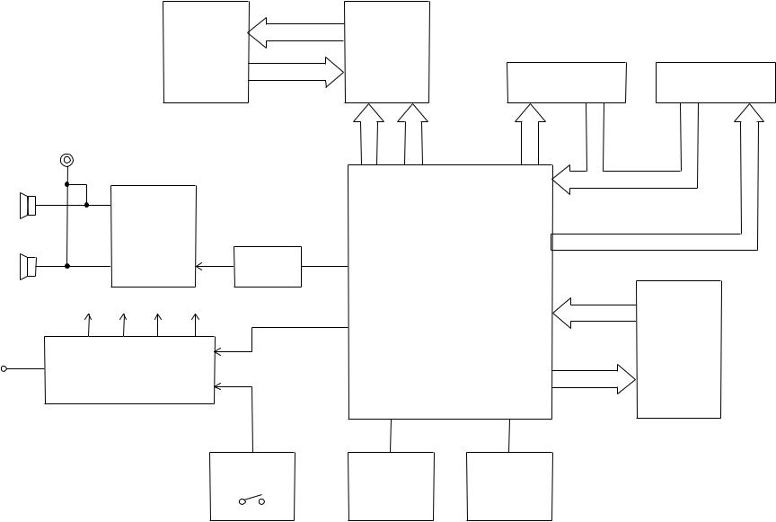
LCD
Phones/Output
Speaker
(L)
Power Amp.
LA4598
IC101
Speaker
(R)
VC VCC DVDD AVDD
DC + 9 V IN |
Power Supply Circuit |
|
|
|
Q101 ~ Q103, D104 |
BLOCK DIAGRAM
COM1 ~ COM16 |
|
|
|
LCD Driver |
|
|
|
KS0066U-10B |
|
|
|
LSI3 |
|
|
|
SEG1 ~ SEG40 |
|
|
|
|
RS |
|
|
DB4 ~ DB7 |
R/W |
KO8 ~ |
|
E |
|||
|
KO12 |
||
|
|
Filter
Q105 CPU MSM 6755C-17
LSI1
APO
Buttons |
Keyboard |
KI0 ~ KI6
KO0 ~ KO7
MD0 ~ MD7
ROM(2M-bit)
MA0 ~ MA17
UM23C2101M
7384/Q
LSI2
Power Switch |
Reset IC |
Oscillator |
||||
|
|
|
|
|
IC1 |
X1, Q1 |
|
|
|
|
|
|
|

CIRCUIT DESCRIPTION
KEY MATRIX
|
KI0 |
KI1 |
KI2 |
KI3 |
KI4 |
KI5 |
KI6 |
|
|
|
|
|
|
|
|
|
|
KO0 |
C2 |
G#2 |
E3 |
C4 |
G#4 |
E5 |
C6 |
|
|
|
|
|
|
|
|
|
|
KO1 |
C#2 |
A2 |
F3 |
C#4 |
A4 |
F5 |
|
|
|
|
|
|
|
|
|
|
|
KO2 |
D2 |
A#2 |
F#3 |
D4 |
A#4 |
F#5 |
|
|
|
|
|
|
|
|
|
|
|
KO3 |
D#2 |
B2 |
G3 |
D#4 |
B4 |
G5 |
|
|
|
|
|
|
|
|
|
|
|
KO4 |
E2 |
C3 |
G#3 |
E4 |
C5 |
G#5 |
|
|
|
|
|
|
|
|
|
|
|
KO5 |
F2 |
C#3 |
A3 |
F4 |
C#5 |
A5 |
|
|
|
|
|
|
|
|
|
|
|
KO6 |
F#2 |
D3 |
A#3 |
F#4 |
D5 |
A#5 |
|
|
|
|
|
|
|
|
|
|
|
KO7 |
G2 |
D#3 |
B3 |
G4 |
D#5 |
B5 |
|
|
|
|
|
|
|
|
|
|
|
KO8 |
— |
+ |
0 |
Tempo |
Tempo |
Volume |
Volume |
|
Down |
Up |
Down |
Up |
|||||
|
|
|
|
|||||
KO9 |
3 |
2 |
1 |
Start/ |
Synchro/ |
Chord |
Accomp |
|
Stop |
Fill-in |
Book |
Volume |
|||||
|
|
|
|
|||||
KO10 |
6 |
5 |
4 |
Transpose/ |
Song |
Rhythm |
Tone |
|
Tune |
Bank |
|||||||
|
|
|
|
|
|
|||
KO11 |
9 |
8 |
7 |
Fingered |
CASIO |
Normal |
Power Off |
|
Chord |
||||||||
|
|
|
|
|
|
|
||
KO12 |
FF |
Right |
Play/ |
Stop |
Left |
Rewind |
|
|
Pause |
|
|||||||
|
|
|
|
|
|
|
||
|
|
|
|
|
|
|
|
NOMENCLATURE OF KEYS
C#2 D#2 |
F#2 G#2 |
A#2 |
C#3 D#3 |
F#3 G#3 |
A#3 |
C#4 D#4 |
F#4 G#4 |
A#4 |
C#5 D#5 |
F#5 G#5 |
A#5 |
C2 |
D2 |
E2 |
F2 |
G2 |
A2 |
B2 |
C3 |
D3 |
E3 |
F3 |
G3 |
A3 |
B3 |
C4 |
D4 |
E4 |
F4 |
G4 |
A4 |
B4 |
C5 |
D5 |
E5 |
F5 |
G5 |
A5 |
B5 |
C6 |
— 3 —
CPU (LSI1: MSM6755C-17)
The CPU reads sound data from the ROM in accordance with the pressed key and the selected tone; the CPU can read rhythm data simultaneously when a rhythm pattern is selected. Then it provides the left and the right channels’ waveforms separately, by converting the data into the waveforms with two built-in DACs. The CPU also controls key and button input. The following table shows the pin functions of LSI1.
Pin No. |
Terminal |
In/Out |
Function |
|
|
|
|
1 |
MA14 |
Out |
Address bus |
|
|
|
|
2, 3 |
NCO |
— |
Not used |
|
|
|
|
4 ~ 19 |
MA0 ~ MA13 |
Out |
Address bus |
|
|
|
|
13 |
MRDB |
Out |
Read enable signal |
|
|
|
|
17 |
MCSB |
— |
Not used |
|
|
|
|
20 ~ 27 |
MD0 ~ MD7 |
In/Out |
Data bus |
|
|
|
|
28, 29 |
NC1, NC2 |
— |
Not used |
|
|
|
|
30 |
DGND |
In |
Ground (0 V) source |
|
|
|
|
31 |
DVCC |
In |
+5 V source |
|
|
|
|
32, 33 |
XTLO, XTLI |
In/Out |
20 MHz clock input/output |
|
|
|
|
34 |
NC3 |
— |
Not used |
|
|
|
|
35 |
RSTB |
In |
Reset signal input |
|
|
|
|
36 |
P24/RXD |
— |
MIDI signal input |
|
|
|
|
37 |
P25/TXD |
— |
MIDI signal output |
|
|
|
|
38 |
NMI |
In |
Power ON signal input. Connected to +5 V. |
|
|
|
|
39 |
APO |
Out |
APO (Auto Power Off) signal output |
|
|
|
|
40 |
NC4 |
— |
Not used |
|
|
|
|
41 |
REFH |
Out |
Terminal for the internal DAC |
|
|
|
|
42, 43 |
NC5, NC6 |
— |
Not used |
|
|
|
|
44 |
DAOR |
Out |
Sound waveform signal output |
|
|
|
|
45 |
NC7 |
— |
Not used |
|
|
|
|
46 |
AVdac |
In |
+5 V source for the internal DAC |
|
|
|
|
47 |
DAOL |
Out |
Left channel sound waveform output |
|
|
|
|
48 |
REFL |
Out |
Terminal for the internal DAC and ADC |
|
|
|
|
49 |
AGdac |
In |
Ground source for internal DAC |
|
|
|
|
50 |
AGadc |
In |
Ground source for internal ADC |
|
|
|
|
51 |
ANI |
In |
Not used |
|
|
|
|
52 |
AVadc |
In |
+5 V source for the internal ADC |
|
|
|
|
53 |
NC8 |
— |
Not used |
|
|
|
|
54 |
MOD0 |
In |
Mode selection terminal. Connected to +5 V. |
|
|
|
|
55, 56 |
MOD1, MOD2 |
In |
Mode selection terminal. Connected to ground. |
|
|
|
|
57 |
P40 |
— |
Not used |
|
|
|
|
58 ~ 64 |
KI0/P30 ~ KI7/P36 |
In |
Terminals for key/button input signal |
|
|
|
|
65 |
KI7/P37 |
— |
Not used |
|
|
|
|
66 ~ 73 |
KO0/P50 ~ KO7/P57 |
Out |
Terminals for key scan signal |
|
|
|
|
— 4 —
 Loading...