


CTK-620L
100 RHYTHMS
RHYTHMS
TONE
|
|
|
137 TONES |
|
|
|
REVERB |
|
|
|
TOUCH |
|
|
|
RESPONSE |
MODE |
VOLUME |
INTRO |
SYNCHRO/ENDING |
|
|
|
METRONOME |
|
|
|
TEMPO |
POWER |
MAX |
|
|
FULL RANGE |
|
BEAT |
|
|
CHORD |
|
|
|
FINGERED |
|
|
|
CASIO CHORD |
|
ACCOMP |
|
NOMAL |
|
VOLUME |
|
MIN |
NORMAL/FILL-IN |
VARIATION/FILL-IN |
 START/STOP
100 SONG BANK
SONG
BANK
|
MUSICAL INFORMATION SYSTEM |
|
TRANSPOSE/ |
|
SONG BANK |
|
|
|
|
REVERB |
|
|
|
|
|
|
|||
|
|
|
TUNE/MIDI |
|
|
|
|
|
|
HALL |
|
GM |
|
|
|
|
|
(TIE) |
3 |
|
|
|
|
|
|
|
|
||
STAGE |
|
LAYER |
LAYER |
|
|
|
7 |
8 |
9 |
ROOM |
|
SPLIT |
|
|
|
|
|||
TOUCH |
|
MEMORY |
SPLIT RHYTHM |
|
TONE |
|
|
|
|
RESPONSE |
|
|
|
4 |
5 |
6 |
|||
KEY LIGHT |
|
STEP |
|
|
|
|
|||
|
|
|
MEMORY |
TRACK 1 |
TRACK 2 |
|
|
DEMO |
|
|
|
|
|
|
|
|
|
|
|
|
SONG BANK CONTROLLER |
|
|
LEFT |
RIGHT |
1 |
2 |
3 |
|
|
|
|
|
||||||
KEY LIGHT |
STOP PLAY/PAUSE REW |
FF |
STEP |
3-STEP LESSON |
|||||
STEP 1 |
STEP 2 STEP 3 |
|
|
|
|||||
|
|
|
|
REST |
|
|
|||
|
|
|
|
1 |
2 |
3 |
0 |
|
|
CTK-620L
ELECTRONIC KEYBOARD

|
CONTENTS |
|
Page |
Specifications ............................................................................................................................................ |
1 |
Block Diagram ........................................................................................................................................... |
3 |
Circuit Description ..................................................................................................................................... |
4 |
Adjustment .............................................................................................................................................. |
12 |
Major Waveforms .................................................................................................................................... |
13 |
Printed Circuit Boards ............................................................................................................................. |
14 |
Schematic Diagrams ............................................................................................................................... |
15 |
Exploded View ........................................................................................................................................ |
28 |
Parts List ................................................................................................................................................. |
29 |
|
SPECIFICATIONS |
GENERAL |
|
Keyboard: |
61 standard-size keys, 5 octaves (with touch response on/off) |
Key light system: |
Can be turned on and off (up to 10 keys can be lit at the same time) |
Tones: |
137 (128 General MIDI tones + 9 drum tones); with layer and split |
Rhythm instrument tones: |
61 |
Polyphony: |
24 notes maximum (12 for certain tones) |
Digital effects: |
3 reverb types (HALL, STAGE, ROOM) |
Auto accompaniment |
|
Rhythm patterns: |
100 |
Tempo: |
Variable (216 steps, = 40 to 255) |
Chords: |
3 fingering methods (CASIO CHORD, FINGERED, FULL RANGE |
|
CHORD) |
Rhythm controller: |
START/STOP, INTRO, NORMAL/NORMARL FILL-IN, VARIATION/ |
|
VARIATION FILL-IN, SYNCHRO/ENDING |
Accomp volume: |
0 to 127 (128 steps) |
3-step lesson: |
3 lessons (step 1, 2, 3) |
Playback: |
Repeat play of a single tune |
Song bank |
|
Number of tunes: |
100 |
Controllers: |
PLAY/PAUSE, STOP, FF, REW, LEFT, RIGHT |
Musical information function: |
Tone, Auto Accompaniment, Song Bank numbers and names; staff nota- |
|
tion, tempo, metronome, measure and beat number, step lesson display, |
|
chord name, dynamic mark, fingering, pedal operation |
Metronome: |
On/Off |
Beat specification: |
1 to 6 |
Memory |
|
Songs: |
2 |
Recording tracks: |
2 |
Recording methods: |
Real-time, step |
Memory capacity: |
Approximately 5,200 notes (total for two songs) |
MIDI: |
16 multi-timbre receive, GM Level 1 standard |
Other functions |
|
Transpose: |
25 steps (–12 semitones to +12 semitones) |
Tuning: |
101 steps (A4 = approximately 440 Hz ± 50 cents) |
Terminals |
|
MIDI terminals: |
IN, OUT |
Assignable jack: |
Standard jack (sustain, sostenuto, soft, rhythm start/stop) |
Headphone/output terminal: |
Stereo standard jack |
Output Impedance: |
100 Ω |
Output voltage: |
4.5 V (RMS) MAX |
— 1 —

Power jack |
9 V DC |
||
Power supply: |
2-way |
||
Batteries: |
Six D-size batteries |
||
Battery life: |
Approximately 5 hours continuous operation on manganese batteries |
||
AC adaptor: |
AD-5 |
||
Auto power off: |
Turns power off approximately six minutes after last key operation. En- |
||
|
abled under battery power only, can be disabled manually. |
||
Speaker output: |
2.5 W + 2.5 W |
||
Power consumption: |
9 V |
--- |
7.7 W |
Dimensions (HWD): |
96.1 × 39.1 × 14.4 cm (37 7/8 × 15 3/8 × 5 11/16 inches) |
||
Weight: |
Approximately 6.0 kg (13.25 lbs) (without batteries) |
||
ELECTRICAL
Current drain with 9 V DC: |
200 mA ± 20 % |
No sound output |
|
Maximum volume |
1090 mA ± 20 % |
with 10 keys from F1 to A2 pressed in French Horn |
|
Volume: maximum, Touch response: maximum |
|
Reverb: stage |
|
Speaker output level (Vrms with 4 Ω load each channel): |
|
with key C1 for R-ch, F1 for L-ch in French Horn |
2300 mV ± 20 % |
Volume: maximun, Touch response: maximum |
|
Reverb: stage |
|
Phone output level (Vrms with 8 Ω load each channel): |
|
with key C1 for R-ch, F1 for L-ch in French Horn |
180 mV ± 20 % |
Volume: maximun, Touch response: maximum |
|
Reverb: stage |
|
Output level (Vrms with 47 Ω load each channel): |
|
with key C1 for R-ch, F1 for L-ch in French Horn |
2600 mV ± 20 % |
Volume: maximun, Touch response: maximum |
|
Reverb: stage |
|
Minimum operating voltage: |
6.3 V |
About General MIDI
General MIDI standardizes MIDI data for all sound source types, regardless of manufacturer. General MIDI specifies such factors as tone numbering, drum sounds, and available MIDI channels for all sound sources. This standard makes it possible for all MIDI equipment to reproduce the same nuances when playing General MIDI data, regardless of the manufacturer of the sound source.
This keyboard supports General MIDI, so it can be used to play commercially available pre-recorded General MIDI data and General MIDI data send to it from a personal computer.
— 2 —
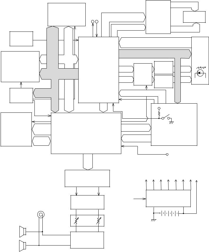
BLOCK DIAGRAM
|
|
Working Storage |
|
|
|
|
|
LCD Driver |
SEG1 ~ SEG40 |
||
|
|
|
|
|
|
|
|
||||
|
|
RAM (256K-bit) |
MIDI |
PO10, PO17 |
|
|
|
|
|||
|
|
|
LSI4 |
|
|
|
LCD |
||||
|
|
|
OUT |
IN |
|
|
LSI401 |
||||
|
|
|
PO22, PO23 |
|
|
||||||
|
|
TC55257DFL-70L(EL) |
|
|
|
|
|
||||
|
|
|
|
|
|
|
|
|
|||
|
|
|
|
|
|
PA4 ~ PA6 |
SED1278F0A |
|
|||
|
|
|
|
|
|
|
|
COM1 ~ COM16 |
|||
|
|
|
RACEB |
|
|
|
|
|
|||
Reset IC IC1 |
|
|
|
|
|
|
|
|
|
||
RESET |
MA0 |
MD0 |
|
|
|
|
|
|
|
|
|
RN5VD40AA |
|
|
|
|
|
FI0 ~ FI7 |
|
||||
~ |
|
|
|
|
|
|
|||||
|
|
~ |
|
|
|
|
|
Illuminant |
|||
|
|
MA14 |
MD7 |
|
|
|
|
|
SI0 ~ SI7 |
||
|
|
|
|
|
|
|
|
||||
|
|
|
|
|
CPU |
|
|
|
KC0 ~ KC7 |
Keyboard |
|
Sound Source ROM |
MD0 ~ MD15 |
|
|
|
|
|
|
L21 |
|||
|
|
|
|
|
|
LED |
|||||
(24M-bit) |
|
|
|
|
LSI1 |
|
GA |
|
|
~ L23 |
|
LSI3 |
|
|
|
|
MD0 ~ 3 |
|
|
Driver |
|
||
LH536PNV |
MA0 ~ MA19 |
|
|
LSI7 |
|
|
Q12 ~ Q14 |
||||
GT913F(T) |
|
|
|
||||||||
|
MCSB0 |
|
MA0 ~ 2 |
UPD65005 |
LED |
|
|||||
|
|
|
|
|
|
GF-419 |
|
LED |
|||
|
|
|
|
|
|
|
Driver |
||||
RDCEB |
|
|
|
|
|
|
|
|
L0 |
||
|
|
|
|
|
LCBE |
|
|
Q1 ~ Q11 |
|||
|
MCSB0, 1 |
|
|
|
|
|
|
|
~ L20 |
||
|
|
|
|
KI0 ~ KI2 |
|
|
|
||||
Chip Selector |
|
|
|
|
|
|
|
||||
MA19 |
|
|
|
|
|
|
|
|
|||
IC2,3 |
|
|
|
|
|
|
|
|
|
|
|
|
|
|
|
|
|
|
|
|
|
|
|
|
|
MA0, |
|
LRCK, SO |
FI9 |
|
|
|
|
||
|
|
|
FI10 |
|
|
VDD |
|
||||
|
|
MA1 |
|
BCK, SINK |
|
|
|
||||
|
CE1B |
|
NMI |
|
|
|
Power Switch |
||||
|
|
|
|
|
|
|
|
|
|||
Effect RAM |
ECEB |
|
|
|
|
|
|
|
|
|
|
|
|
|
DSP |
|
|
|
|
|
|
|
|
(256K-bit) |
EA0 ~ |
|
|
|
PA0, PA1 |
|
|
|
|
||
|
|
|
|
|
|
Buttons |
|||||
LSI5 |
EA14 |
|
|
LSI2 |
|
|
|
|
|
||
TC55257DFL- |
|
|
|
|
|
|
|
|
|
|
|
EIO0 ~ |
|
|
|
|
PB0 ~ PB3 |
|
|
|
|
||
70L(EL) |
|
HG51B277FB-1 |
|
|
|
|
|||||
|
EIO7 |
|
|
|
|
|
|
|
|||
|
|
|
|
|
|
|
|
|
|
|
|
|
|
|
|
|
|
PB4 |
|
|
|
|
|
LRCK |
|
Assingnable Jack |
|
|
|
||
SO |
|
|
|
BCK |
|
|
|
|
D/A Converter |
LCDD |
LVDD DVDD VLCC |
|
VCC AVDD VDD VC |
||
|
LSI6 |
||
|
|
|
|
|
UPD6379GR-E1 |
|
|
R OUT |
|
L OUT |
Power Supply Circuit |
|
|
APO |
|
|
Filter |
|
Q201 ~ Q208, |
Phones/ |
|
D206 ~ 208, D210 |
|
Q213 ~ Q216 |
|
||
Output |
|
|
|
Speakers |
Main |
|
|
Volume |
|
|
|
|
|
|
|
(L) |
|
|
|
|
Power Amplifier |
|
|
|
IC201 |
|
|
(R) |
TA8229K |
|
|
— 3 —
CIRCUIT DESCRIPTION
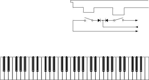
KEY MATRIX
|
KC0 |
KC1 |
KC2 |
KC3 |
KC4 |
KC5 |
KC6 |
KC7 |
|
|
|
|
|
|
|
|
|
FI0 |
C2 (1) |
C#2 (1) |
D2 (1) |
D#2 (1) |
E2 (1) |
F2 (1) |
F#2 (1) |
G2 (1) |
|
|
|
|
|
|
|
|
|
SI0 |
C2 (2) |
C#2 (2) |
D2 (2) |
D#2 (2) |
E2 (2) |
F2 (2) |
F#2 (2) |
G2 (2) |
|
|
|
|
|
|
|
|
|
FI1 |
G#2 (1) |
A2 (1) |
A#2 (1) |
B2 (1) |
C3 (1) |
C#3 (1) |
D3 (1) |
D#3 (1) |
|
|
|
|
|
|
|
|
|
SI1 |
G#2 (2) |
A2 (2) |
A#2 (2) |
B2 (2) |
C3 (2) |
C#3 (2) |
D3 (2) |
D#3 (2) |
|
|
|
|
|
|
|
|
|
FI2 |
E3 (1) |
F3 (1) |
F#3 (1) |
G3 (1) |
G#3 (1) |
A3 (1) |
A#3 (1) |
B3 (1) |
|
|
|
|
|
|
|
|
|
SI2 |
E3 (2) |
F3 (2) |
F#3 (2) |
G3 (2) |
G#3 (2) |
A3 (2) |
A#3 (2) |
B3 (2) |
|
|
|
|
|
|
|
|
|
FI3 |
C4 (1) |
C#4 (1) |
D4 (1) |
D#4 (1) |
E4 (1) |
F4 (1) |
F#4 (1) |
G4 (1) |
|
|
|
|
|
|
|
|
|
SI3 |
C4 (2) |
C#4 (2) |
D4 (2) |
D#4 (2) |
E4 (2) |
F4 (2) |
F#4 (2) |
G4 (2) |
|
|
|
|
|
|
|
|
|
FI4 |
G#4 (1) |
A4 (1) |
A#4 (1) |
B4 (1) |
C5 (1) |
C#5 (1) |
D5 (1) |
D#5 (1) |
|
|
|
|
|
|
|
|
|
SI4 |
G#4 (2) |
A4 (2) |
A#4 (2) |
B4 (2) |
C5 (2) |
C#5 (2) |
D5 (2) |
D#5 (2) |
|
|
|
|
|
|
|
|
|
FI5 |
E5 (1) |
F5 (1) |
F#5 (1) |
G5 (1) |
G#5 (1) |
A5 (1) |
A#5 (1) |
B5 (1) |
|
|
|
|
|
|
|
|
|
SI5 |
E5 (2) |
F5 (2) |
F#5 (2) |
G5 (2) |
G#5 (2) |
A5 (2) |
A#5 (2) |
B5 (2) |
|
|
|
|
|
|
|
|
|
FI6 |
C6 (1) |
C#6 (1) |
D6 (1) |
D#6 (1) |
E6 (1) |
F6 (1) |
F#6 (1) |
G6 (1) |
|
|
|
|
|
|
|
|
|
SI6 |
C6 (2) |
C6# (2) |
D6 (2) |
D#6 (2) |
E6 (2) |
F6 (2) |
F#6 (2) |
G6 (2) |
|
|
|
|
|
|
|
|
|
FI7 |
G#6 (1) |
A6 (1) |
A#6 (1) |
B6 (1) |
C7 (1) |
|
|
|
|
|
|
|
|
|
|
|
|
SI7 |
G#6 (2) |
A6 (2) |
A#6 (2) |
B6 (2) |
C7 (2) |
|
|
|
|
|
|
|
|
|
|
|
|
BUTTON MATRIX
|
KC0 |
KC1 |
KC2 |
KC3 |
KC4 |
KC5 |
KC6 |
KC7 |
|||||
|
|
|
|
|
|
|
|
|
|
|
|
|
|
KI0 |
MEMORY |
STEP 2 |
3 |
TONE |
5 |
TEMPO |
TEMPO |
SYNCHRO/ |
|||||
ENDING |
|||||||||||||
|
|
|
|
|
|
||||||||
|
|
|
|
|
|
|
|
|
|
|
|
||
|
|
|
|
|
|
|
|
|
|
|
|
|
|
KI1 |
STEP |
STEP 3 |
— |
7 |
6 |
ACC. VOL. |
TIME |
METRO |
|||||
|
|
|
|
|
|
|
|
|
|
|
|
|
|
KI2 |
STEP 1 |
0 |
+ |
4 |
DEMO |
TOUCH |
REVERB |
|
|||||
|
|
|
|
|
|
|
|
|
|
|
|
|
|
FI9 |
LAYER |
TRACK 1/ |
2 |
RHYTHM |
9 |
PLAY/PAUSE |
STOP |
KEYLIGHT |
|||||
RIGHT |
|||||||||||||
|
|
|
|
|
|
||||||||
|
|
|
|
|
|
|
|
|
|
|
|
||
FI10 |
SPLIT |
TRACK 1/ |
1 |
SONG |
8 |
FF |
REWIND |
TRANSPOSE/ |
|||||
LEFT |
|
|
|
|
|
|
TUNE/MIDI |
||||||
|
|
|
|
|
|
|
|
|
|
|
|||
|
PA0 |
PA1 |
|
|
|
|
|
PB0 |
INTRO |
FULL RANGE |
|
CHORD |
|||
|
|
||
|
|
|
|
PB1 |
NORMAL |
FINGERED |
|
FILL-IN |
|||
|
|
||
|
|
|
|
PB2 |
VARIATION |
CASIO |
|
FILL-IN |
CHORD |
||
|
|||
PB3 |
START/ |
NORMAL |
|
STOP |
|||
|
|
— 4 —
LED MATRIX
|
L0 |
L1 |
L2 |
L3 |
L4 |
L5 |
L6 |
L7 |
L8 |
L9 |
L10 |
|
|
|
|
|
|
|
|
|
|
|
|
L21 |
A2# |
F4 |
B4 |
E5 |
A5 |
D6 |
G6 |
C7 |
A6# |
G6# |
F6# |
|
|
|
|
|
|
|
|
|
|
|
|
L22 |
G2# |
E4 |
A4 |
D5 |
G5 |
C6 |
F6 |
B6 |
A5# |
C6# |
D6# |
|
|
|
|
|
|
|
|
|
|
|
|
L23 |
C2 |
D4 |
G4 |
C5 |
F5 |
B5 |
E6 |
A6 |
G5# |
F5# |
D5# |
|
|
|
|
|
|
|
|
|
|
|
|
|
L11 |
L12 |
L13 |
L14 |
L15 |
L16 |
L17 |
L18 |
L19 |
L20 |
|
|
|
|
|
|
|
|
|
|
|
L21 |
C3# |
D3# |
F3# |
G2 |
C3 |
F3 |
D4# |
C4# |
A3# |
G3# |
|
|
|
|
|
|
|
|
|
|
|
L22 |
F2# |
D2# |
C2# |
F2 |
B2 |
E3 |
F4# |
G4# |
A4# |
C5# |
|
|
|
|
|
|
|
|
|
|
|
L23 |
|
|
D2 |
E2 |
A2 |
D3 |
G3 |
A3 |
B3 |
C4 |
|
|
|
|
|
|
|
|
|
|
|
Key
Note: Each key has two contacts,
the first conatct (1) and second contact (2).
|
FI |
Second contact (2) |
First contact (1) |
|
KC |
|
SI |
NOMENCLATURE OF KEYS
C#2 D#2 |
F#2 G#2 A#2 |
C#3 D#3 |
F#3 G#3 A#3 |
C#4 D#4 |
F#4 G#4 A#4 |
C#5 D#5 |
F#5 G#5 A#5 |
C#6 D#6 |
F#6 G#6 A#6 |
C2 |
D2 |
E2 |
F2 |
G2 |
A2 |
B2 |
C3 |
D3 |
E3 |
F3 |
G3 |
A3 |
B3 |
C4 |
D4 |
E4 |
F4 |
G4 |
A4 |
B4 |
C5 |
D5 |
E5 |
F5 |
G5 |
A5 |
B5 |
C6 |
D6 |
E6 |
F6 |
G6 |
A6 |
B6 |
C7 |
— 5 —
POWER SUPPLY CIRCUIT
The power supply circuit generates seven voltages as shown in the following table. VDD voltage is always generated. The others are controlled by APO signal from the CPU.
Name |
Voltage |
For operation of |
|
|
|
|
|
VDD |
+5 V |
CPU, Reset IC, DSP, Sound source ROM, Working storage RAM, Effect RAM, |
|
LED driver |
|||
|
|
||
|
|
|
|
DVDD |
+5 V |
CPU, Sustain jack, MIDI jack |
|
|
|
|
|
AVDD |
+5 V |
DAC, Filter |
|
|
|
|
|
LVDD |
+5 V |
GA |
|
|
|
|
|
VCC |
+9 V |
Power amplifier |
|
|
|
|
|
VLCC |
+2 V |
Pilot lamp |
|
|
|
|
|
LCDD |
+5.6 V |
LCD driver |
|
|
|
|
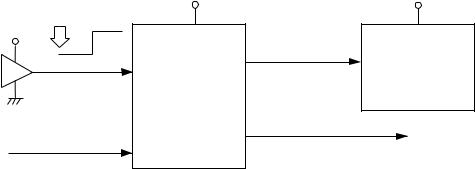
RESET CIRCUIT
When batteries are set or an AC adapter is connected, the reset IC provides a low pulse to the CPU. The CPU then initializes its internal circuit, and clears the working storage RAM.
When the power switch is pressed, the CPU receives a low pulse of POWER signal. The CPU sends APO signal to the power supply circuit, also sends a reset signal to the DSP.
Battery set |
|
VDD |
|
|
|
||
VDD |
|
|
|
RESET |
RSTB |
PLE |
|
|
CPU |
||
Reset IC |
|
||
|
LSI1 |
||
IC1 |
|
||
GT913F |
|||
RN5VD40AA |
|||
|
|
||
POWER |
NMI |
SCK0 |
|
|
|
||
From power switch |
|
|
|
|
VDD |
Reset signal |
DSP |
RESB |
|
|
LSI2 |
HG51B277FB-1 |
|
APO |
|
To power supply circuit |
|
— 6 —
CPU (LSI1: GT913F)
The 16-bit CPU contains a 1k-byte RAM, three 8-bit I/O ports, two timers, a key controller and serial interfaces. The CPU detects key velocity by counting the time between first-key input signal FI and second-key SI from the keyboard. The CPU reads sound data and velocity data from the sound source ROM in accordance with the selected tone; the CPU can read rhythm data simultaneously when a rhythm pattern is selected. Then the CPU provides 16-bit serial sound data to the DSP. The CPU also controls MIDI input/output and stores sequencer data into the working storage RAM.
The following table shows the pin functions of LSI1.
Pin No. |
Terminal |
In/Out |
Function |
|
1 |
TXD0 |
Out |
Not used |
|
|
|
|
|
|
2 |
RXD0 |
In |
Not used |
|
|
|
|
|
|
3 |
SCK0 |
Out |
APO (Auto Power Off) signal output |
|
|
|
|
|
|
4 |
TXD1 |
Out |
MIDI signal output |
|
|
|
|
|
|
5 |
RXD1 |
In |
MIDI signal input |
|
|
|
|
|
|
6 |
SCK1 |
Out |
1 MHZ synchronizing pulse output |
|
|
|
|
|
|
7 |
AVCC |
In |
DVDD (+5 V) source |
|
|
|
|
|
|
|
|
|
AC adaptor detection terminal. |
|
8 |
AN0 |
In |
+5 V when the keyboard is powered by batteries and |
|
becomes 0 V to cancel the APO function when AC |
||||
|
|
|
||
|
|
|
adaptor is connected. |
|
|
|
|
|
|
9 |
AN1 |
— |
Not used. Connected to ground. |
|
|
|
|
|
|
10 |
AGND |
In |
Ground (0 V) source |
|
|
|
|
|
|
11 |
BCK |
Out |
Bit clock output |
|
|
|
|
|
|
12 |
SO |
Out |
Serial sound data output |
|
|
|
|
|
|
13 |
LRCK |
Out |
Word clock output |
|
|
|
|
|
|
14 |
GND |
In |
Ground (0 V) source |
|
|
|
|
|
|
15, 16 |
XLT0, XLT1 |
In/Out |
30 MHz clock input/output |
|
|
|
|
|
|
17 |
VCC |
In |
+5 V source |
|
|
|
|
|
|
18, 19 |
MD0, MD1 |
In |
Mode selection terminal |
|
|
|
|
|
|
20 |
RSTB |
In |
Reset signal input |
|
|
|
|
|
|
21 |
NMI |
In |
Power ON signal input |
|
|
|
|
|
|
22 |
INT/P10 |
In/Out |
Data bus for the LCD driver |
|
|
|
|
|
|
23 ~ 30 |
FI0 ~ FI3 |
In |
Terminal for key input signal |
|
SI0 ~ SI3 |
||||
|
|
|
||
|
|
|
|
|
31 ~ 38 |
KC0 ~ KC7 |
Out |
Terminal for key scan signal |
|
|
|
|
|
|
39 ~ 46 |
FI4 ~ FI7 |
In |
Terminal for key input signal |
|
SI4 ~ SI7 |
||||
|
|
|
||
|
|
|
|
|
47, 48 |
FI8, SI8 |
— |
Not used |
|
|
|
|
|
|
49 |
FI9 |
In |
Terminal for button input signal |
|
|
|
|
|
|
50 |
SI9 |
In |
Data bus for LCD driver |
|
|
|
|
|
|
51 |
FI10 |
In |
Terminal for button input signal |
|
|
|
|
|
|
52 |
SI10/P23 |
Out |
Data bus for the LCD driver |
|
|
|
|
|
|
53 ~ 55 |
KI0 ~ KI2 |
In |
Terminal for button input signal |
|
|
|
|
|
|
56 |
MWNB |
Out |
Write enable signal for the DSP |
|
|
|
|
|
— 7 —
Pin No. |
Terminal |
In/Out |
Function |
|
|
|
|
|
|
57 ~ 76 |
MA0 ~ MA19 |
Out |
Address bus |
|
|
|
|
|
|
77, 78 |
MCSB0, MCSB1 |
Out |
Chip enable signal output for the sound source ROM, |
|
working RAM and DSP |
||||
|
|
|
||
79 |
MCSB2 |
Out |
Not used |
|
|
|
|
|
|
80 |
VCC |
In |
+5 V source |
|
|
|
|
|
|
81 |
GND |
In |
Ground (0 V) source |
|
|
|
|
|
|
82 |
MRDB |
Out |
Read enable signal output for the sound source ROM |
|
|
|
|
|
|
83 ~ 98 |
MD0 ~ MD15 |
In/Out |
Data bus |
|
|
|
|
|
|
99 |
PLE |
Out |
Reset signal output for the DSP |
|
|
|
|
|
|
100 |
P17 |
In/Out |
Data bus for the LCD driver |
|
|
|
|
|
DIGITAL SIGNAL PROCESSOR (LSI2: HG51B227FB-1)
The DSP receives 16-bit serial sound data output from the CPU and adds the selected effect to the sound data using the effect RAM. Then the DSP provides the sound data to the DAC. The DSP also controls button input/ output and GA.
The following table shows the pin functions of LSI2.
Pin No. |
Terminal |
In/Out |
Function |
|
|
|
|
1 ~ 3, 80 |
PB0 ~ PB3 |
In |
Button input terminals |
|
|
|
|
4 |
PB4 |
In |
ASSIGNABLE Jack input |
|
|
|
|
5 |
SO |
Out |
Serial sound data output for the DAC |
|
|
|
|
6 |
WCKO |
Out |
Word clock output for the DAC |
|
|
|
|
7 |
VDD3 |
In |
+5 V source |
|
|
|
|
8 |
TEST |
— |
Not used |
|
|
|
|
9 |
RESB |
In |
Reset signal input |
|
|
|
|
10 |
VSS2 |
In |
Ground (0 V) source |
|
|
|
|
11, 12 |
XIN, XOUT |
In/Out |
20 MHz clock input/output |
|
|
|
|
13 |
WCKI |
In |
Word clock input from the CPU |
|
|
|
|
14 |
SI |
In |
Serial sound data input from the CPU |
|
|
|
|
15 |
BCKI |
In |
Bit clock input from the CPU |
|
|
|
|
16 |
SINC |
In |
1 MHz synchronizing pulse input |
|
|
|
|
17 |
VDD2 |
In |
+5 V source |
|
|
|
|
18 ~ 25 |
IO0 ~ IO7 |
In/Out |
Data bus |
|
|
|
|
26 |
RCEB |
Out |
Chip enable signal output for the GA |
|
|
|
|
27 |
VSS3 |
In |
Ground (0 V) source |
|
|
|
|
28 |
AD1 |
In |
Address bus |
|
|
|
|
29 |
OEB |
Out |
Output enable signal for working storage RAM |
|
|
|
|
30 |
WEB |
In |
Write enable signal for working strage RAM |
|
|
|
|
31 |
VDD3 |
In |
+5 V source |
|
|
|
|
32 |
CE2 |
In |
Chip enable signal input. High active. |
|
|
|
|
33 |
AD0 |
In |
Address bus |
|
|
|
|
— 8 —
Pin No. |
Terminal |
In/Out |
Function |
|
|
|
|
|
|
34 |
CE1B |
In |
Chip enable signal input. Low active. |
|
|
|
|
|
|
35 ~ 41, 43 |
EIO0 ~ EIO7 |
In/Out |
Data bus for the effect RAM |
|
|
|
|
|
|
42 , 44, 46 ~ 48, |
EA0 ~ EA14 |
Out |
Address bus for the effect RAM |
|
51 ~ 59, 61 |
||||
|
|
|
||
45 |
ECEB |
Out |
Chip enable signal output for the effect RAM |
|
|
|
|
|
|
49 |
EOEB |
Out |
Output enable signal for the effect RAM |
|
|
|
|
|
|
50 |
VSS3 |
In |
Ground (0 V) source |
|
|
|
|
|
|
60 |
BWEB |
Out |
Write enable signal output for the effect RAM |
|
|
|
|
|
|
62, 66, 70, 74, 78 |
VSS2 |
In |
Ground source |
|
|
|
|
|
|
63, 67, 71, 75, 79 |
VDD2 |
In |
+5 V source |
|
|
|
|
|
|
64, 65 |
PA0, PA1 |
Out |
Button scan signal output |
|
|
|
|
|
|
68, 69, 77 |
PA2, PA3, PA7 |
— |
Not used |
|
|
|
|
|
|
72 |
PA4 |
Out |
Data/command signal for LCD driver |
|
|
|
|
|
|
73 |
PA5 |
Out |
Read/write signal for LCD driver |
|
|
|
|
|
|
76 |
PA6 |
Out |
Chip enable signal for LCD driver |
|
|
|
|
|
LCD DRIVER (LSI401: SED1278F0A)
The LCD driver can drive a dot matrix LCD having 40 segment and 15 common lines. The LSI contains 240 graphic symbols in the built-in character generator ROM, and stores 80 characters in the built-in display data RAM. In accordance with command from the CPU, the LSI is capable of displaying up to 16 characters simultaneously. The following table shows the pin functions of LSI 401.
Pin No. |
Terminal |
In/Out |
Function |
||
|
|
|
|
|
|
1 ~ 22, |
SEG1 ~ SEG40 |
Out |
Segment signal output |
||
63 ~ 80 |
|||||
|
|
|
|
||
23 |
VSS |
— |
GND (0 V) source |
||
|
|
|
|
|
|
24, 25 |
OSC1, OSC2 |
In/Out |
Terminals for the built-in clock pulse generator.The external |
||
resistor connected determines the oscillation requency. |
|||||
|
|
|
|||
|
|
|
LCD drive voltage input. |
||
26 ~ 30 |
V1 ~ V5 |
In |
Those voltages are used for generating the stepped pulse of |
||
|
|
|
the LCD drive signals. |
||
31, 32 |
LP, XCLS |
— |
Not used |
||
|
|
|
|
||
33 |
VDD |
In |
DVDD (+5 V) source |
||
34, 35 |
FR, DO |
— |
Not used |
||
|
|
|
|
|
|
36 |
RS |
In |
Data/command determination terminal. |
||
High: data, Low: command |
|||||
|
|
|
|||
|
|
|
|
|
|
37 |
R/W |
In |
Read/write terminal. High: read, Low: write |
||
|
|
|
Chip enable signal. |
||
38 |
E |
In |
High: enable, the writing is done at fall edge. |
||
|
|
|
Low: disenable |
||
39 ~ 42 |
DB0 ~ DB3 |
— |
Not used. Connected to GND (0 V) |
||
|
|
|
|
||
43 ~ 46 |
DB4 ~ DB7 |
In/Out |
Data bus |
||
47 ~ 53, |
COM1 ~ COM7 |
Out |
Common signal/output |
||
55 ~ 62 |
COM9 ~ COM16 |
||||
|
|
|
|||
54 |
COM8 |
— |
Not used |
|
|
|
|
|
|
|
|
— 9 —
 Loading...