


48HC
Single Package Rooftop
Gas Heating/Electric Cooling Unit with Puronr (R---410A) Refrigerant
Sizes: 17, 20, 24, 28
Installation Instructions
NOTE: Read the entire instruction manual before starting the installation
TABLE OF CONTENTS
SAFETY CONSIDERATIONS . . . . . . . . . . . . . . . . . . . . |
2 |
INSTALLATION . . . . . . . . . . . . . . . . . . . . . . . . . . . . . . . |
9 |
Jobsite Survey . . . . . . . . . . . . . . . . . . . . . . . . . . . . . . . . |
9 |
Step 1 - Plan for Unit Location . . . . . . . . . . . . . . . . . . |
9 |
Roof Mount . . . . . . . . . . . . . . . . . . . . . . . . . . . . . . . |
9 |
Step 2 - Plan for Sequence of Unit Installation . . . . . |
10 |
Curb-Mount Installation . . . . . . . . . . . . . . . . . . . . |
10 |
Pad-Mount Installation . . . . . . . . . . . . . . . . . . . . . |
10 |
Frame-Mount Installation . . . . . . . . . . . . . . . . . . . |
10 |
Step 3 - Inspect Unit . . . . . . . . . . . . . . . . . . . . . . . . . . |
10 |
Step 4 - Provide Unit Support . . . . . . . . . . . . . . . . . . |
10 |
Roof Curb Mount . . . . . . . . . . . . . . . . . . . . . . . . . |
10 |
Slab Mount (Horizontal Units Only) . . . . . . . . . . |
10 |
Alternate Unit Support |
|
(In Lieu of Curb or Slab Mount) . . . . . . . . . . . . . |
10 |
Step 5 - Field Fabricate Ductwork . . . . . . . . . . . . . . . |
14 |
Step 6 - Rig and Place Unit . . . . . . . . . . . . . . . . . . . . |
14 |
Positioning on Curb . . . . . . . . . . . . . . . . . . . . . . . |
15 |
Step 7 - Horizontal Duct Connection . . . . . . . . . . . . |
15 |
Step 8 - Install Outside Air Hood — Factory Option . . |
15 |
Step 9 - Install Flue Hood and Combustion Air Hood . . |
16 |
Step 10 - Install Gas Piping . . . . . . . . . . . . . . . . . . . . |
16 |
Gas Supply Line . . . . . . . . . . . . . . . . . . . . . . . . . . |
16 |
Factory-Option Thru-Base Connections . . . . . . . |
18 |
Step 11 - Install External Condensate Trap and Line . . |
19 |
Step 12 - Make Electrical Connections . . . . . . . . . . . |
19 |
Field Power Supply . . . . . . . . . . . . . . . . . . . . . . . . |
19 |
Units without Factory-Installed Disconnect . . . . |
20 |
Units with Factory-Installed Disconnect . . . . . . . |
20 |
All Units . . . . . . . . . . . . . . . . . . . . . . . . . . . . . . . . |
20 |
Convenience Outlets . . . . . . . . . . . . . . . . . . . . . . . |
20 |
Factory-Option Thru-Base Connections . . . . . . |
22 |
Units without Thru-Base Connections . . . . . . . . . 22 Field Control Wiring . . . . . . . . . . . . . . . . . . . . . . . 22 Thermostat . . . . . . . . . . . . . . . . . . . . . . . . . . . . . . . 22 Unit without Thru-Base Conversion Kit . . . . . . . 22 Heat Anticipator Settings . . . . . . . . . . . . . . . . . . . 23
Transformer Connection
for 208-v Power Supply . . . . . . . . . . . . . . . . . . . . . 23 Humidi-MiZerR Control Connections . . . . . . . . . . 24 Humidi-MiZer - Space RH Controller . . . . . . . . 24 PremierLinkt (Factory Option) . . . . . . . . . . . . . . . 26 Supply Air Temperature (SAT) Sensor . . . . . . . . . 29 Outdoor Air Temperature (OAT) Sensor . . . . . . . 29 EconoMi$er2 . . . . . . . . . . . . . . . . . . . . . . . . . . . . . 29 Field Connections . . . . . . . . . . . . . . . . . . . . . . . . . . 29 Space Sensors . . . . . . . . . . . . . . . . . . . . . . . . . . . . 31 Connect Thermostat . . . . . . . . . . . . . . . . . . . . . . . 31 Configure the Unit for Thermostat Mode . . . . . . 31 Economizer Controls . . . . . . . . . . . . . . . . . . . . . . . . 32 Indoor Air Quality (CO2) Sensor . . . . . . . . . . . . . 32 Outdoor Air Quality Sensor . . . . . . . . . . . . . . . . . 32
Space Relative Humidity Sensor or
Humidistat Connections . . . . . . . . . . . . . . . . . . . . 33 Smoke Detector/Fire Shutdown (FSD) . . . . . . . . . 34 Filter Status Switch . . . . . . . . . . . . . . . . . . . . . . . . 34 Supply Fan Status Switch . . . . . . . . . . . . . . . . . . . 34 Remote Occupied Switch . . . . . . . . . . . . . . . . . . . 34 Power Exhaust (output) . . . . . . . . . . . . . . . . . . . . . 34 CCN Communication Bus . . . . . . . . . . . . . . . . . . 35
RTU Open Control System . . . . . . . . . . . . . . . . . . . 36 Supply Air Temperature (SAT) Sensor . . . . . . . . . 39 Outdoor Air Temperature (OAT) Sensor . . . . . . . 39 EconoMi$er2 . . . . . . . . . . . . . . . . . . . . . . . . . . . . . 39
48HC
Field Connections . . . . . . . . . . . . . . . . . . . . . . . . . . 39 Space Temperature (SPT) Sensors . . . . . . . . . . . . 40 Indoor Air Quality (CO2) Sensor . . . . . . . . . . . . . 40 Outdoor Air Quality Sensor . . . . . . . . . . . . . . . . . 41 Space Relative Humidity Sensor or Humidistat . . 41 Smoke Detector/Fire Shutdown (FSD) . . . . . . . . . 42 Connecting Discrete Inputs . . . . . . . . . . . . . . . . . . 42
Communication Wiring - Protocols . . . . . . . . . . . . 43 General . . . . . . . . . . . . . . . . . . . . . . . . . . . . . . . . . 43 Local Access . . . . . . . . . . . . . . . . . . . . . . . . . . . . . 44 RTU Open Troubleshooting . . . . . . . . . . . . . . . . . 44 Outdoor Air Enthalpy Control . . . . . . . . . . . . . . . . . 45 Differential Enthalpy Control . . . . . . . . . . . . . . . . 45 Smoke Detectors . . . . . . . . . . . . . . . . . . . . . . . . . . . 46 Return Air Sensor Tube Installation . . . . . . . . . . . 46 Smoke Detector Test Magnet . . . . . . . . . . . . . . . . 47 Additional Application Data . . . . . . . . . . . . . . . . . 47 Step 13 - Adjust Factory-Installed Options . . . . . . . . 50 Step 14 - Install Accessories . . . . . . . . . . . . . . . . . . . 50
SAFETY CONSIDERATIONS
Improper installation, adjustment, alteration, service, maintenance, or use can cause explosion, fire, electrical shock or other conditions which may cause personal injury or property damage. Consult a qualified installer, service agency, or your distributor or branch for information or assistance. The qualified installer or agency must use factory-authorized kits or accessories when modifying this product. Refer to the individual instructions packaged with the kits or accessories when installing.
Follow all safety codes. Wear safety glasses and work gloves. Use quenching cloths for brazing operations and have a fire extinguisher available. Read these instructions thoroughly and follow all warnings or cautions attached to the unit. Consult local building codes and appropriate national electrical codes (in USA, ANSI/NFPA70, National Electrical Code (NEC); in Canada, CSA C22.1) for special requirements.
It is important to recognize safety information. This is the
safety-alert symbol  . When you see this symbol on the unit and in instructions or manuals, be alert to the potential for personal injury.
Understand the signal words DANGER, WARNING, CAUTION, and NOTE. These words are used with the safety-alert symbol. DANGER identifies the most serious hazards which will result in severe personal injury or death. WARNING signifies hazards which could result in personal injury or death. CAUTION is used to identify unsafe practices, which may result in minor personal injury or product and property damage. NOTE is used to highlight suggestions which will result in enhanced installation, reliability, or operation.
!WARNING
FIRE, EXPLOSION HAZARD
Failure to follow this warning could result in personal injury or death.
Disconnect gas piping from unit when leak testing at pressure greater than 0.5 psig (3450 Pa). Pressures greater than 0.5 psig (3450 Pa) will cause gas valve damage resulting in hazardous condition. If gas valve is subjected to pressure greater than 0.5 psig (3450 Pa), it must be replaced before use. When pressure testing field-supplied gas piping at pressures of 0.5 psig (3450 Pa) or less, a unit connected to such piping must be isolated by closing the manual gas valve.
!WARNING
ELECTRICAL SHOCK HAZARD
Failure to follow this warning could cause personal injury or death.
Before performing service or maintenance operations on unit, always turn off main power switch to unit and install lock(s) and lockout tag(s). Unit may have more than one power switch.
!WARNING
UNIT OPERATION AND SAFETY HAZARD
Failure to follow this warning could cause personal injury, death and/or equipment damage.
Puronr (R-410A) refrigerant systems operate at higher pressures than standard R-22 systems. Do not use R-22 service equipment or components on Puron refrigerant equipment.
!WARNING
PERSONAL INJURY AND ENVIRONMENTAL HAZARD
Failure to follow this warning could cause personal injury or death.
Relieve pressure and recover all refrigerant before system repair or final unit disposal.
Ware safety glasses and gloves when handling refrigerants. Keep torches and other ignition sources away from refrigerants and oils.
!CAUTION
CUT HAZARD
Failure to follow this caution may result in personal injury.
Sheet metal parts may have sharp edges or burrs. Use care and wear appropriate protective clothing, safety glasses and gloves when handling parts and servicing air conditioning equipment.
2
48HC
C10896
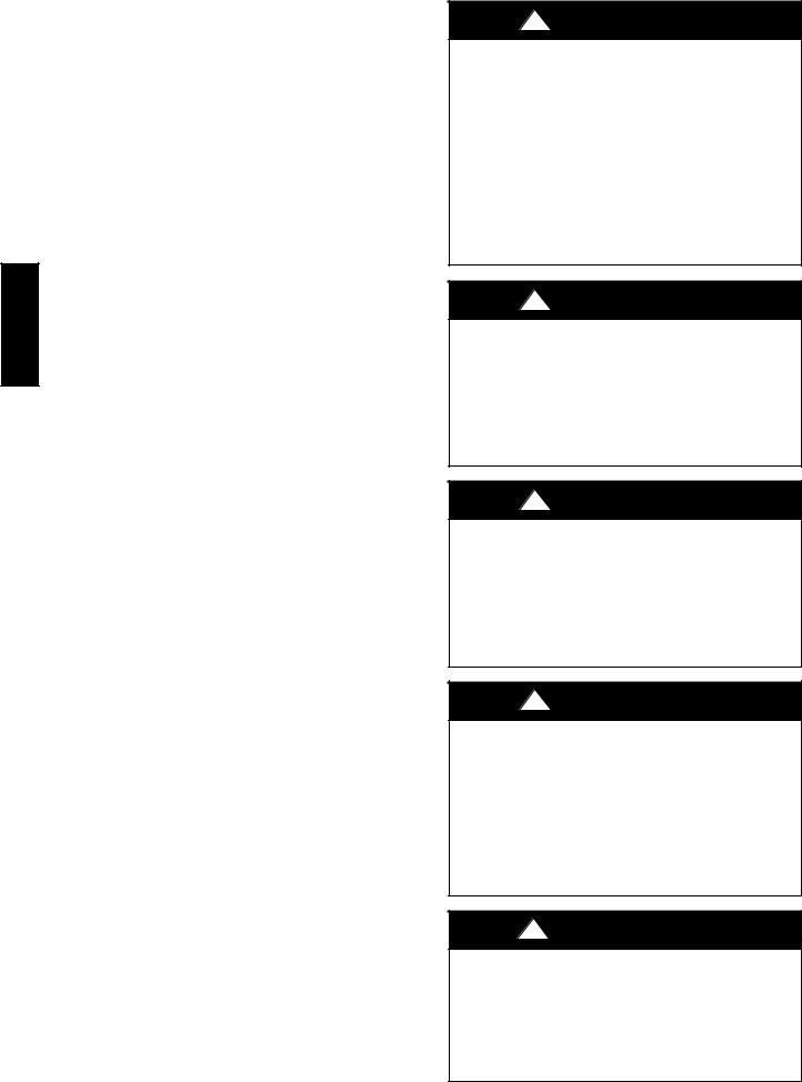
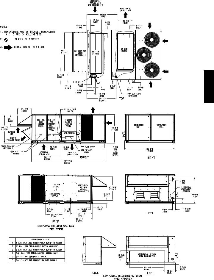
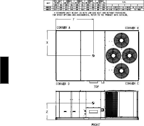
Fig. 1 - Unit Dimensional Drawing – 17 Size Unit
3
48HC
C10897
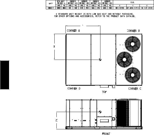
Fig. 1 - Unit Dimensional Drawing – 17 Size Unit (cont.)
4
48HC
C10892
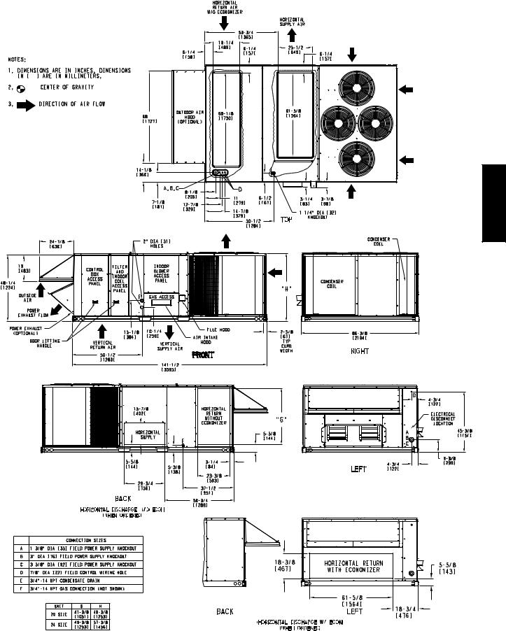
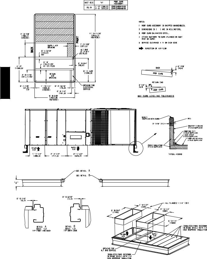
Fig. 2 - Unit Dimensional Drawing – 20 and 24 Size Units
5
48HC
C10893
Fig. 2 - Unit Dimensional Drawing – 20 and 24 Size Units (cont.)
6

48HC
C10900
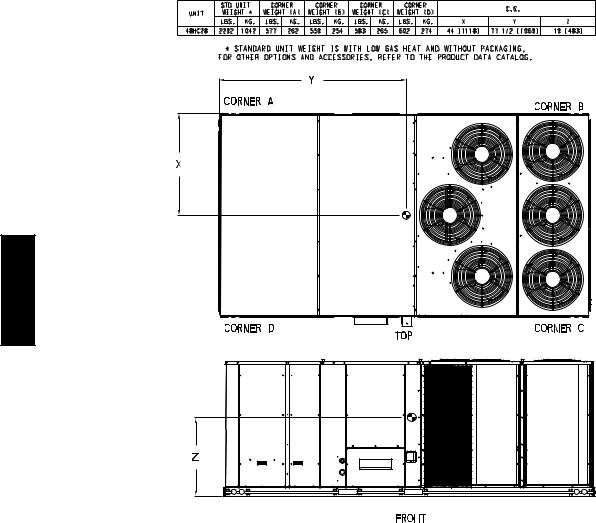
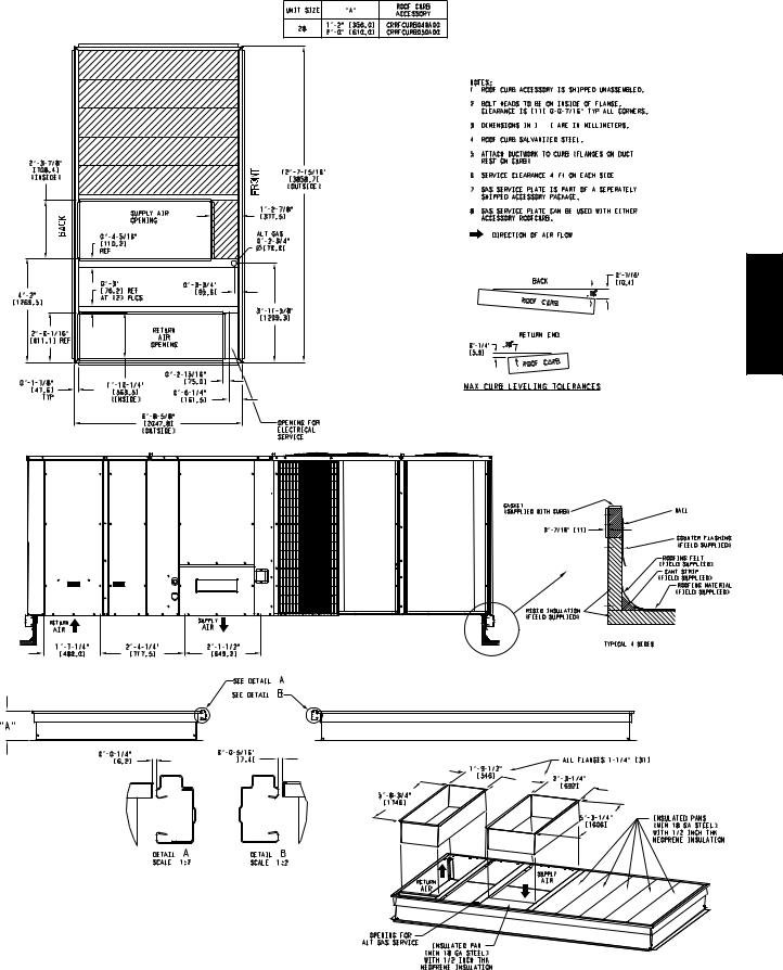
Fig. 3 - Unit Dimensional Drawing – 28 Size Unit
7
48HC
C10901
Fig. 3 - Unit Dimensional Drawing – 28 Size Unit (cont.)
8
INSTALLATION
Jobsite Survey
Complete the following checks before installation.
1.Consult local building codes and the NEC (National Electrical Code) ANSI/NFPA 70 for special installation requirements.
2.Determine unit location (from project plans) or select unit location.
3.Check for possible overhead obstructions which may interfere with unit lifting or rigging.
Step 1 — Plan for Unit Location
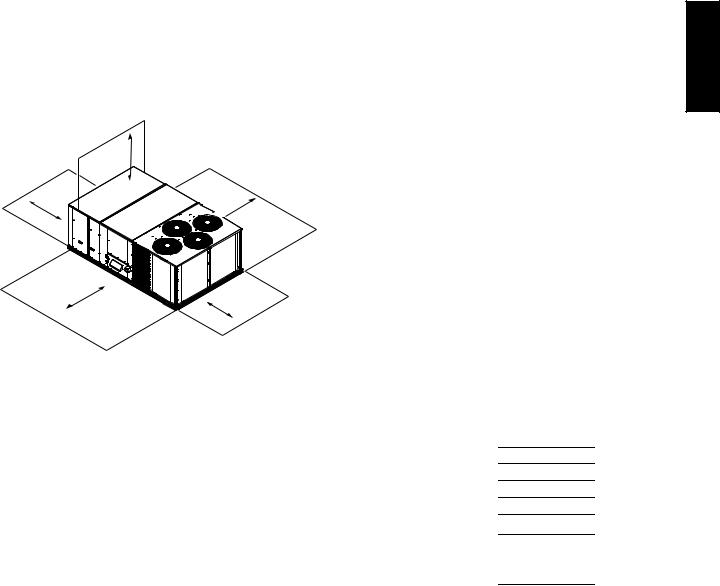
Select a location for the unit and its support system (curb or other) that provides for the minimum clearances required for safety. This includes the clearance to combustible surfaces, unit performance and service access below, around and above unit as specified in unit drawings. See Fig. 4.
NOTE: Consider also the effect of adjacent units.
96” (2438)
36” (914)


 42” (1067)
42” (1067) |
36” (914) |
C10638
Fig. 4 - Service Clearance Dimensional Drawing
Be sure that the unit is installed such that snow will not block the combustion air intake or flute outlet.
Unit may be installed directly on wood flooring or on Class A, B, or C roof-covering material when roof curb is used.
Do not install unit in an indoor location. Do not locate air inlets near exhaust vents or other sources of contaminated air. For proper unit operation, adequate combustion and ventilation air must be provided in accordance with Section 5.3 (Air for Combustion and Ventilation) of the National Fuel Gas Code, ANSI Z223.1 (American National Standards Institute) and NFPA (National Fire Protection Association) 54 TIA--54--84--1. In Canada, installation must be in accordance with the CAN1--B149 installation codes for gas burning appliances.
Although unit is weatherproof, avoid locations that permit water from higher level runoff and overhangs to fall onto the unit.
Locate mechanical draft system flue assembly at least 4 ft (1.2 m) from any opening through which combustion products could enter the building, and at least 4 ft (1.2 m) from any adjacent building (or per local code). Locate the flue assembly at least 10 ft (3.05 m) from an adjacent unit’s fresh air intake hood if within 3 ft (0.91 m) of same elevation (or per local code). When unit is located adjacent to public walkways, flue assembly must be at least 7 ft (2.1 m) above grade.
Select a unit mounting system that provides adequate height to allow installation of condensate trap per requirements. Refer to Step 11 — Install External Condensate Trap and Line – for required trap dimensions.
Roof Mount —
Check building codes for weight distribution requirements. Unit operating weight is shown in Table 1.
Table 1 – Operating Weights
48HC** |
|
|
|
UNIT LB (KG) |
|
|
|
||
|
|
|
|
|
|
|
|
||
17 |
20 |
24 |
28 |
||||||
|
|||||||||
|
|
|
|
|
|
|
|||
Base Unit |
1892 (858) |
2102 (954) |
2247 |
(1019) |
2292 |
(1040) |
|||
|
|
|
|
|
|
|
|
|
|
Economizer |
245 |
(111) |
245 |
(111) |
245 |
(111) |
245 |
(111) |
|
|
|
|
|
|
|
|
|
|
|
Powered Outlet |
32 |
(15) |
32 |
(15) |
32 |
(15) |
32 |
(15) |
|
|
|
|
|
|
|
|
|
|
|
Humidi---MiZerR System |
83 |
(38) |
83 |
(38) |
88 |
(40) |
92 |
(42) |
|
Curb |
|
|
|
|
|
|
|
|
|
14---in/356 mm |
273 |
(124) |
273 |
(124) |
273 |
(124) |
273 |
(124) |
|
24---in/610 mm |
350 |
(159) |
350 |
(159) |
350 |
(159) |
350 |
(159) |
|
|
|
|
|
|
|
|
|
|
|
48HC
9
48HC
Step 2 — Plan for Sequence of Unit Installation
The support method used for this unit will dictate different sequences for the steps of unit installation. For example, on curb-mounted units, some accessories must be installed on the unit before the unit is placed on the curb. Review the following for recommended sequences for installation steps.
Curb-mounted installation —
Install curb
Install field-fabricated ductwork inside curb
Install thru-base service connection fittings (affects curb and unit)
Rig and place unit Remove top skid Install outside air hood
Install smoke detector tube Install combustion air hood Install flue hood
Install gas piping
Install condensate line trap and piping Make electrical connections
Install other accessories
Pad-mounted installation —
Prepare pad and unit supports Rig and place unit
Remove duct covers and top skid
Install smoke detector return air sensor tube
Install field-fabricated ductwork at unit duct openings Install outside air hood
Install combustion air hood Install flue hood
Install gas piping
Install condensate line trap and piping Make electrical connections
Install other accessories
Frame-mounted installation —
Frame-mounted applications generally follow the sequence for a curb installation. Adapt as required to suit specific installation plan.
Step 3 — Inspect unit
Inspect unit for transportation damage. File any claim with transportation agency.
Confirm before installation of unit that voltage, amperage and circuit protection requirements listed on unit data plate agree with power supply provided.
Locate the carton containing the outside air hood parts; see Figs. 5 and 12. Do not remove carton until unit has been rigged and located in final position.
Step 4 — Provide Unit Support
Roof Curb Mount —
Accessory roof curb details and dimensions are shown in Figs. 6, 7 and 8. Assemble and install accessory roof curb in accordance with instructions shipped with the curb.
NOTE: The gasketing of the unit to the roof curb is critical for a watertight seal. Install gasket supplied with the roof curb as shown in Figs. 6, 7 and 8. Improperly applied gasket can also result in air leaks and poor unit performance.
Curb should be level. This is necessary for unit drain to function properly. Unit leveling tolerances are show in Fig. 9. Refer to Accessory Roof Curb Installation Instructions for additional information as required.
Install insulation, cant strips, roofing felt, and counter flashing as shown. Ductwork must be attached to curb and not to the unit. Thru-the-base power connection must be installed before the unit is set on the roof curb. If field-installed thru-the-roof curb gas connections are desired remove knockout in basepan located in the gas section, see Fig. 5 for location. Gas connections and power connections to the unit must be field installed after the unit is installed on the roof curb.
If electric and control wiring is to be routed through the basepan, remove knockouts in basepan located in control box area of access panel; see Fig. 1, 2, or 3 for basepan knockout locations for location. Attach the service connections to the basepan.
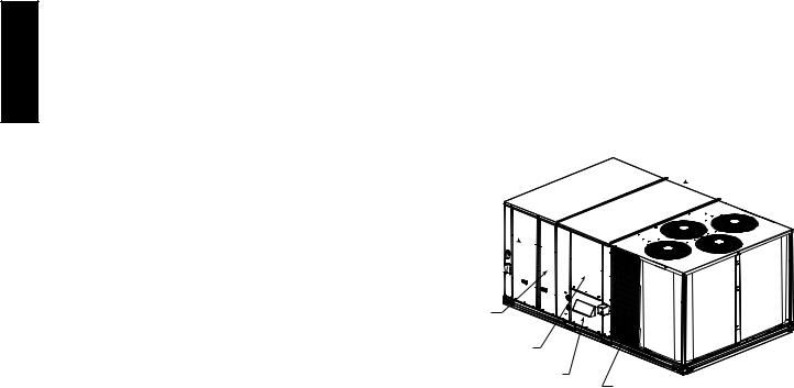
Hood Carton Location
 (rear access panel)
Control Box
Access Panel
Filter and
Indoor Coil
Access Panel
Indoor Blower
Access Panel
Gas Heat
Access Panel Compressor
(each side)
C11154
Fig. 5 - Typical Access Panel and Compressor Locations
Slab Mount (Horizontal Units Only) —
Provide a level concrete slab that extends a minimum of 6–in. (150 mm) beyond unit cabinet. Install a gravel apron in front of condenser coil air inlet to prevent grass and foliage from obstructing airflow.
NOTE: Horizontal units may be installed on a roof curb if required.
Alternate Unit Support (In Lieu of Curb or Slab Mount) —
A non-combustible sleeper rail can be used in the unit curb support area. If sleeper rails cannot be used, support the long sides of the unit with a minimum of 4 equally spaced 4-in. x 4-in. (102 mm x 102 mm) pads on each side. Locate pads so that they support the rails. Make sure to avoid the fork openings.
10
48HC
C10954
Fig. 6 - Roof Curb Details – 17 Size Unit
11
48HC
C10955
Fig. 7 - Roof Curb Details – 20 and 24 Size Units
12
48HC
C10956
Fig. 8 - Roof Curb Details – 28 Size Unit
13
48HC
C
A |
|
MAXIMUM ALLOWABLE |
||
|
DIFFERENCE IN. (MM) |
|||
|
|
|||
|
B |
|
|
|
|
A-B |
B-C |
A-C |
|
|
|
|||
|
|
0.25” (6) |
0.5” (12) |
0.5” (12) |
C10628
Fig. 9 - Unit Leveling Tolerances
Step 5 — Field Fabricate Ductwork
Cabinet return-air static pressure (a negative condition) shall not exceed 0.5 in. wg (87 Pa) with economizer or without economizer.
For vertical ducted applications, secure all ducts to roof curb and building structure. Do not connect ductwork to unit.
Fabricate supply ductwork so that the cross sectional dimensions are equal to or greater than the unit supply duct opening dimensions for the first 18 in. (458 mm) of duct length from the unit basepan.
Insulate and weatherproof all external ductwork, joints, and roof openings with counter flashing and mastic in accordance with applicable codes.
Ducts passing through unconditioned spaces must be insulated and covered with a vapor barrier.
If a plenum return is used on a vertical unit, the return should be ducted through the roof deck to comply with applicable fire codes.
A minimum clearance is not required around ductwork.
!CAUTION
PROPERTY DAMAGE HAZARD
Failure to follow this caution may result in damage to roofing materials.
Membrane roofs can be cut by sharp sheet metal edges. Be careful when placing any sheet metal parts on such roof.
Step 6 — Rig and Place Unit
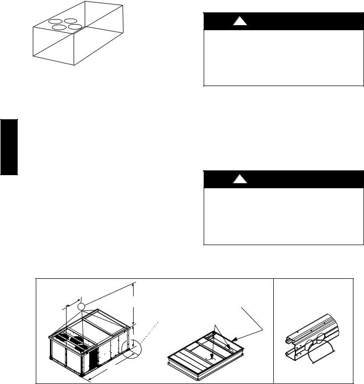
Keep unit upright and do not drop. Spreader bars are not required if top crating is left on unit. Rollers may be used to move unit across a roof. Level by using unit frame as a reference. See Table 1 (on page 9) and Fig. 10 for additional information.
Lifting holes are provided in base rails as shown in Fig. 10. Refer to rigging instructions on unit.
!CAUTION
UNIT DAMAGE HAZARD
Failure to follow this caution may result in equipment damage.
All panels must be in place when rigging. Unit is not designed for handling by fork truck when packaging is removed.
Before setting the unit onto the curb, recheck gasketing on curb.
|
PLACE ALL SEAL STRIP |
DETAIL A |
"914-1371" |
IN PLACE BEFORE PLACING |
|
UNIT ON ROOF CURB. |
|
|
(36"-54") |
|
|
|
|
|
"B" |
|
|
SEE DETAIL A |
DUCT END |
|
|
|
|
"C" |
|
|
"A" |
|
|
|
|
C09107 |
|
MAX WEIGHT |
|
|
DIMENSIONS |
|
|
||
|
|
|
|
|
|
|
||
UNIT |
|
A |
|
B |
|
C |
||
|
|
|
|
|
||||
|
|
|
|
|
|
|
|
|
|
LB |
KG |
IN |
MM |
IN |
MM |
IN |
MM |
|
|
|
|
|
|
|
|
|
48HC**17 |
2339 |
1061 |
127.8 |
3249 |
58.7 |
1491 |
52.3 |
1328 |
|
|
|
|
|
|
|
|
|
48HC**20 |
2549 |
1156 |
141.5 |
3595 |
71.5 |
1816 |
52.3 |
1328 |
|
|
|
|
|
|
|
|
|
48HC**24 |
2699 |
1224 |
141.5 |
3595 |
71.5 |
1816 |
60.3 |
1532 |
|
|
|
|
|
|
|
|
|
48HC**28 |
2748 |
1246 |
157.8 |
4007 |
80.3 |
2040 |
60.3 |
1532 |
|
|
|
|
|
|
|
|
|
NOTES:
1.Dimensions in ( ) are inches.
2.Hook rigging shackles through holes in base rail, as shown in detail “A.” Holes in base rails are centered around the unit center of gravity. Use wooden top to prevent rigging straps from damaging unit.
Fig. 10 - Rigging Details
14
Positioning on Curb —
Position unit on roof curb so that the following clearances are maintained: 1/4 in. (6 mm) clearance between the roof curb and the base rail inside the right and left, 1/2 in. (12 mm) clearance between the roof curb and the base rail inside the front and back. This will result in the distance between the roof curb and the base rail inside on the condenser end of the unit being approximately equal to Details A and B in Figs. 6, 7 and 8.
Do not attempt to slide unit on curb after unit is set. Doing so will result in damage to the roof curb seal.
Although unit is weatherproof, guard against water from higher level runoff and overhangs.
Flue vent discharge must have a minimum horizontal clearance of 48 in. (1220 mm) from electric and gas meters, gas regulators, and gas relief equipment. Minimum distance between unit and other electrically live parts is 48 inches (1220 mm).
Flue gas can deteriorate building materials. Orient unit such that flue gas will not affect building materials. Locate mechanical draft system flue assembly at least 48 in. (1220 mm) from an adjacent building or combustible material.
After unit is in position, remove rigging skids and shipping materials.
Step 7 — Horizontal Duct Connection
Refer to Figs. 1, 2 and 3 for locations and sizes of the horizontal duct connections. Note that there are two different return air duct connection locations – one for unit without an economizer (on back side of unit) and a different one for unit equipped with an economizer (on left end, under the economizer hood). The supply air duct connection is on the back side. See Fig. 11 for top view depicting typical horizontal duct arrangements.
Horizontal |
Supply Air |
|
|
|
|
|
Return Air Duct |
Return Air Duct |
|||||
|
|
|
|
|
|
without |
with Economizer |
||||
|
|
|
|
|
|
Economizer |
|
|
|
|
|
|
|
|
|
|
|
|
|
|
|
|
C10626 |
|
|
|
|
|
|
||||||
|
Supply |
Return without |
|
Return with |
|||||||
|
Economizer |
|
Economizer |
||||||||
|
|
|
|
||||||||
Location |
Back |
Back |
|
Left end |
|||||||
|
|
|
|
|
|
|
|
|
|
|
|
Height --- In. (mm) |
157/ |
(402) |
493/ |
8 |
(1253) |
|
183/ |
8 |
(467) |
||
|
8 |
|
|
|
|
|
|
|
|||
Width --- in. (mm) |
293/ |
(756) |
233/ |
8 |
(593) |
|
615/ |
8 |
(1564) |
||
|
4 |
|
|
|
|
|
|
|
|||
Fig. 11 - Horizontal Duct Opening Dimensions
Field-supplied (3/4-inch) flanges should be attached to horizontal duct openings (see Fig. 11) and all ductwork should be secured to the flanges. Insulate and weatherproof all external ductwork, joints, and roof or building openings with counter flashing and mastic in accordance with applicable codes.
Step 8 — Install Outside Air Hood — Factory Option
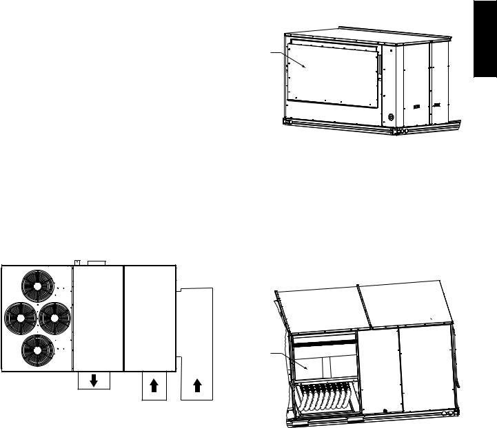
The outside air hood for factory-option economizer and two-position damper is shipped in knock-down form and requires field assembly. The panel for the hood top is shipped on the end of the unit (see Fig. 12). The remaining parts for the hood assembly (including side panels, filters and tracks) are shipped in a carton that is secured to the rear of the blower assembly. Access the carton location through rear panel (see Fig. 13).
Hood Top |
48HC |
Shipping |
|
Position |
|
C09134
Fig. 12 - Hood Top – Shipping Position
To remove the hood parts package:
1.Remove the back blower access panel.
2.Locate and cut the strap, being careful to not damage any wiring.
3.Carefully lift the hood package carton through the back blower access opening.
See Fig. 14 for identification of the various parts of the hood assembly.
Hood
Package
C09133
Fig. 13 - Hood Package – Shipping Location
15

To assemble the outside air hood:
1.Remove hood top panel from shipping position on unit end.
2.Install four angles to the upper end panel using the screws provided.
3.Apply seal strip to mating flanges on the side plates of the hood (see Fig. 14).
|
|
|
|
Apply Seal Strips |
3 |
Apply Seal Strip |
|
|
|
|
to the back of |
|
|
|
|
|
|
these surfaces |
|
to the front of |
|
|
|
Apply Seal Strip |
|
|
this flange |
|
|
|
|
|
|
|
|
|
|
to the front of |
|
|
7 |
|
Apply Seal Strips |
|
this flange |
|
|
|
|
|
|
7 |
|
|
|
|
to the back of |
|
|
|
|
|
|
these flanges |
|
|
|
|
|
|
2 |
|
|
|
|
2 |
|
|
|
|
|
4 |
|
|
|
|
|
|
4 |
|
|
|
|
|
4 |
5 |
|
|
|
|
|
|
||
|
|
|
4 |
|
|
|
|
|
|
|
|
|
|
|
|
|
|
|
|
6 |
|
|
|
|
|
|
Apply Seal Strip |
|
|
|
|
|
|
to the back of |
48HC |
|
|
|
1 |
|
this flange |
Seal Strips |
5 |
6 |
|
|
|
|
|
|
|
|
|
||
|
|
Item # |
Description |
Qty |
|
|
|
|
1 |
Angles |
4 |
|
|
|
|
2 |
Side Plates |
2 |
|
|
|
|
|
3 |
Hood |
1 |
|
|
|
|
4 |
Outdoor Air Screens |
4 |
|
|
|
|
5 |
Side Filter Supports |
2 |
|
|
|
|
6 |
Side Drip Angles |
2 |
|
|
|
|
7 |
Top Diverters |
2 |
|
C09079
Fig. 14 - Hood Part Identification and Seal Strip
Application Areas
4.Secure side plates to panel using the screws provided.
5.Apply seal strip to mating flange of the hood (see Fig. 14).
6.Secure top flange using screws provided in kit.
7.Install outdoor air screens by sliding them into the channel formed by the four angles installed in step 2. Make sure that the screens extend across the entire length of the hood.
8.Install side filter supports using the screws provided.
9.Install side drip angles using the screws provided.
10.Run a continuous length of seal strip across the hood covering the engagement holes in the lower hood.
11.Install top diverter using the screws provided.
12.On units with barometric relief, remove screws at bottom of relief damper. Do not discard damper door.
C09090
Fig. 15 - Hood Assembly – Completed
Step 9 — Install Flue Hood and Combustion Air Hood
The flue hood is shipped screwed to the fan deck inside the burner compartment. Remove the burner access panel and then remove the flue hood from its shipping location. Using the screws provided, install flue hood in the location shown in Fig. 16.
The combustion air hood is attached to the back of the burner access panel. Remove the two screws securing the hood to the back of the burner access panel. Using the two screws, re-attach the hood to the front of the burner access panel as shown in Fig. 16.
Combustion |
Flue Hood |
|
Air Hood |
||
|
C10744
Fig. 16 - Flue Hood and Combustion Air Hood Details
Step 10 — Install Gas Piping
Installation of the gas piping must be in accordance with local building codes and with applicable national codes. In U.S.A., refer to NFPA 54/ANSI Z223.1 National Fuel Gas Code (NFGC). In Canada, installation must be accordance with the CAN/CSA B149.1 and CAN/CSA B149.2 installation codes for gas burning appliances.
This unit is factory equipped for use with Natural Gas fuel at elevations up to 2000 ft (610 m) above sea level. Unit may be field converted for operation at elevations above 2000 ft (610 m) and/or for use with liquefied petroleum fuel. See accessory kit installation instructions regarding these accessories.
NOTE: Furnace gas input rate on rating plate is for installation up to 2000 ft (610 m) above sea level. In U.S.A. the input rating for altitudes above 2000 ft (610 m) must be derated by 4% for each 1000 ft (305 m) above sea level. In Canada the input rating must be derated by 10% for altitudes of 2000 ft (610 m) to 4500 ft (1372 m) above sea level.
For natural gas applications, gas pressure at unit gas connection must not be less than 5 in. wg (1246 Pa) or greater than 13 in. wg (3240 Pa) while the unit is operating. For liquified petroleum applications, the gas pressure must not be less than 11 in. wg (2740 Pa) or greater than 13 in. wg (3240 Pa) at the unit connection.
Gas Supply Line —
The gas supply pipe enters the unit adjacent to the burner access panel on the front side of the unit, through the grommeted hole. The gas connection to the unit is made to the 3/4 in. FPT gas inlet port on the unit gas valve.
Table 2 lists typical 3/4 inch NPT (National Pipe Thread) field supplied pipe fittings required for Thru-Base gas supply, starting from the unit gas valve (see Fig. 17).
16
 Loading...