


48TC*D08---D14 Nominal 7.5 to 12.5 Tons
With Puron® (R---410A) Refrigerant
Service and Maintenance Instructions
TABLE OF CONTENTS
SAFETY CONSIDERATIONS . . . . . . . . . . . . . . . . . . . . 1 UNIT ARRANGEMENT AND ACCESS . . . . . . . . . . . 2 SUPPLY FAN (BLOWER) SECTION . . . . . . . . . . . . . . 4 COOLING . . . . . . . . . . . . . . . . . . . . . . . . . . . . . . . . . . . . 6 PURONR (R-410A) REFRIGERANT . . . . . . . . . . . . . . 8 COOLING CHARGING CHARTS . . . . . . . . . . . . . . . . 10 CONVENIENCE OUTLETS . . . . . . . . . . . . . . . . . . . . 16 SMOKE DETECTORS . . . . . . . . . . . . . . . . . . . . . . . . . 17 PROTECTIVE DEVICES . . . . . . . . . . . . . . . . . . . . . . . 24 GAS HEATING SYSTEM . . . . . . . . . . . . . . . . . . . . . . 25 CONDENSER COIL SERVICE . . . . . . . . . . . . . . . . . . 35 PREMIERLINKt CONTROL . . . . . . . . . . . . . . . . . . . 36 RTU-MP CONTROL SYSTEM . . . . . . . . . . . . . . . . . . 44 ECONOMI$ER SYSTEMS . . . . . . . . . . . . . . . . . . . . . . 57 WIRING DIAGRAMS . . . . . . . . . . . . . . . . . . . . . . . . . 66 PRE-START-UP . . . . . . . . . . . . . . . . . . . . . . . . . . . . . . 69 START-UP, GENERAL . . . . . . . . . . . . . . . . . . . . . . . . 69 START-UP, PREMIERLINK CONTROL . . . . . . . . . . 71 START-UP, RTU-MP CONTROL . . . . . . . . . . . . . . . . 71 OPERATING SEQUENCES . . . . . . . . . . . . . . . . . . . . . 75 FASTENER TORQUE VALUES . . . . . . . . . . . . . . . . . 85 APPENDIX I. MODEL NUMBER SIGNIFICANCE . 87 APPENDIX II. PHYSICAL DATA . . . . . . . . . . . . . . . . 88 APPENDIX III. FAN PERFORMANCE . . . . . . . . . . . 90 APPENDIX IV. WIRING DIAGRAM LIST . . . . . . . . 96
APPENDIX V. MOTORMASTER SENSOR LOCATIONS . . . . . . . . . . . . . . . . . . . . . . . . . . . . . . . . . 97
UNIT START-UP CHECKLIST . . . . . . . . . . . . . . . . . . 98
SAFETY CONSIDERATIONS
Installation and servicing of air-conditioning equipment can be hazardous due to system pressure and electrical components. Only trained and qualified service personnel should install, repair, or service air-conditioning equipment. Untrained personnel can perform the basic maintenance functions of replacing filters. Trained service personnel should perform all other operations.
When working on air-conditioning equipment, observe precautions in the literature, tags and labels attached to the unit, and other safety precautions that may apply. Follow all safety codes. Wear safety glasses and work gloves. Use quenching cloth for unbrazing operations. Have fire extinguishers available for all brazing operations.
Follow all safety codes. Wear safety glasses and work gloves. Use quenching cloth for brazing operations. Have fire extinguisher available. Read these instructions thoroughly and follow all warnings or cautions attached to the unit. Consult local building codes and National Electrical Code (NEC) for special requirements.
Recognize safety information. This is the safety-alert
symbol  . When you see this symbol on the unit and in instructions or manuals, be alert to the potential for personal injury.
Understand the signal words DANGER, WARNING, and CAUTION. These words are used with the safety-alert symbol. DANGER identifies the most serious hazards which will result in severe personal injury or death. WARNING signifies a hazard which could result in personal injury or death. CAUTION is used to identify unsafe practices which may result in minor personal injury or product and property damage. NOTE is used to highlight suggestions which will result in enhanced installation, reliability, or operation.
48TC
!WARNING
FIRE, EXPLOSION HAZARD
Failure to follow this warning could result in personal injury, death and/or property damage.
Refer to the User’s Information Manual provided with this unit for more details.
Do not store or use gasoline or other flammable vapors and liquids in the vicinity of this or any other appliance.
What to do if you smell gas:
DO NOT try to light any appliance.
DO NOT touch any electrical switch, or use any phone in your building.
IMMEDIATELY call your gas supplier from a neighbor’s phone. Follow the gas supplier’s instructions.
If you cannot reach your gas supplier, call the fire department.
!WARNING
ELECTRICAL OPERATION HAZARD
Failure to follow this warning could result in personal injury or death.
Before performing service or maintenance operations on unit, turn off main power switch to unit. Electrical shock and rotating equipment could cause injury.
!WARNING
ELECTRICAL OPERATION HAZARD
Failure to follow this warning could result in personal injury or death.
Units with convenience outlet circuits may use multiple disconnects. Check convenience outlet for power status before opening unit for service. Locate its disconnect switch, if appropriate, and open it. Tag-out this switch, if necessary.
!WARNING
UNIT OPERATION AND SAFETY HAZARD
Failure to follow this warning could cause personal injury, death and/or equipment damage.
PuronR (R-410A) refrigerant systems operate at higher pressures than standard R-22 systems. Do not use R-22 service equipment or components on PuronR refrigerant equipment.
!WARNING
FIRE, EXPLOSION HAZARD
Failure to follow this warning could result in personal injury or death.
Disconnect gas piping from unit when pressure testing at pressure greater than 0.5 psig. Pressures greater than 0.5 psig will cause gas valve damage resulting in hazardous condition. If gas valve is subjected to pressure greater than 0.5 psig, it must be replaced before use. When pressure testing field-supplied gas piping at pressures of 0.5 psig or less, a unit connected to such piping must be isolated by closing the manual gas valve(s).
!CAUTION
CUT HAZARD
Failure to follow this caution may result in personal injury.
Sheet metal parts may have sharp edges or burrs. Use care and wear appropriate protective clothing, safety glasses and gloves when handling parts and servicing air conditioning units.
UNIT ARRANGEMENT AND ACCESS
General
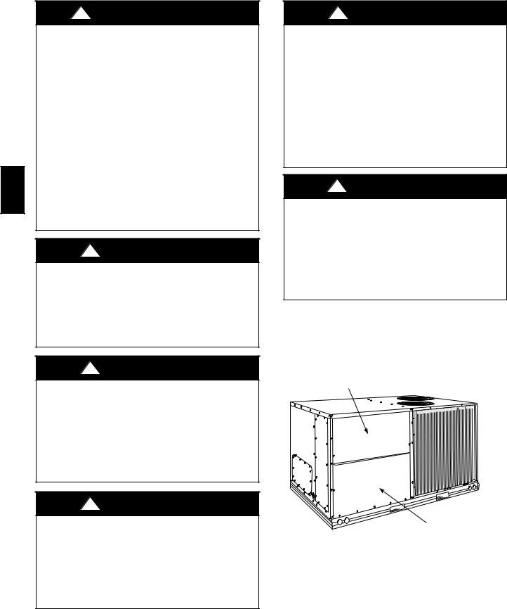
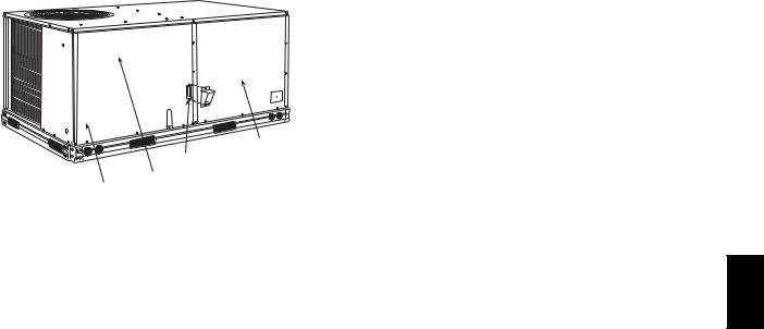
Fig. 1 and Fig. 2 show general unit arrangement and access locations.
FILTER ACCESS PANEL
INDOOR COIL ACCESS PANEL
C06023
Fig. 1 - Typical Access Panel Locations (Back)
2
|
BLOWER |
|
FLUE OPENING |
ACCESS |
|
PANEL |
||
|
||
CONTROL BOX |
|
COMPRESSOR
C08450
Fig. 2 - Typical Access Panel Location (Front)
Routine Maintenance
These items should be part of a routine maintenance program, to be checked every month or two, until a specific schedule for each can be identified for this installation:
Quarterly Inspection (and 30 days after initial start)
S Return air filter replacement
S Outdoor hood inlet filters cleaned S Belt tension checked
S Belt condition checked
S Pulley alignment checked
S Fan shaft bearing locking collar tightness checked S Condenser coil cleanliness checked
S Condensate drain checked
Seasonal Maintenance
These items should be checked at the beginning of each season (or more often if local conditions and usage patterns dictate):
Air Conditioning
S Condenser fan motor mounting bolts tightness S Compressor mounting bolts
S Condenser fan blade positioning
S Control box cleanliness and wiring condition S Wire terminal tightness
S Refrigerant charge level S Evaporator coil cleaning
S Evaporator blower motor amperage
Heating
S Heat exchanger flue passageways cleanliness S Gas burner condition
S Gas manifold pressure
S Heating temperature rise
Economizer or Outside Air Damper
S Inlet filters condition
S Check damper travel (economizer)
S Check gear and dampers for debris and dirt
Air Filters and Screens
Each unit is equipped with return air filters. If the unit has an economizer, it will also have an outside air screen. If a manual outside air damper is added, an inlet air screen will also be present.
Each of these filters and screens will need to be periodically replaced or cleaned.
Return Air Filters
Return air filters are disposable fiberglass media type. Access to the filters is through the small lift-out panel located on the rear side of the unit, above the evaporator/return air access panel. (See Fig. 1.)
To remove the filters:
1.Grasp the bottom flange of the upper panel.
2.Lift up and swing the bottom out until the panel disengages and pulls out.
3.Reach inside and extract the filters from the filter rack.
4.Replace these filters as required with similar replacement filters of same size.
To re-install the access panel:
1.Slide the top of the panel up under the unit top panel.
2.Slide the bottom into the side channels.
3.Push the bottom flange down until it contacts the top of the lower panel (or economizer top).
IMPORTANT: DO NOT OPERATE THE UNIT WITHOUT THESE FILTERS!
Outside Air Hood
Outside air hood inlet screens are permanent aluminum-mesh type filters. Check these for cleanliness. Remove the screens when cleaning is required. Clean by washing with hot low-pressure water and soft detergent and replace all screens before restarting the unit. Observe the flow direction arrows on the side of each filter frame.
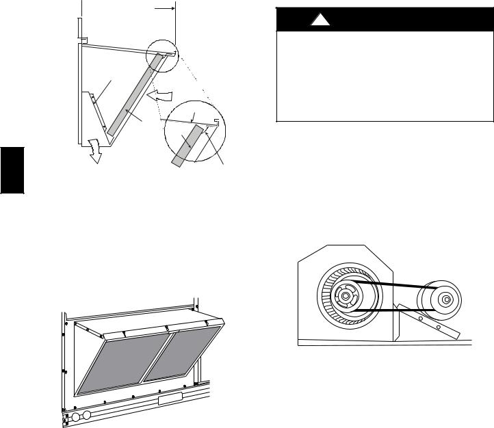
Economizer Inlet Air Screen
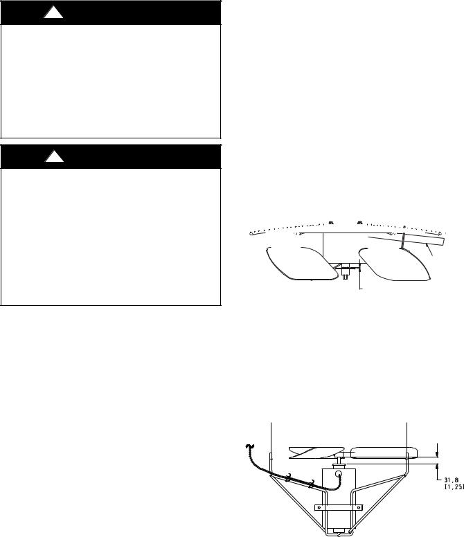
This air screen is retained by spring clips under the top edge of the hood. (See Fig. 3.)
48TC
3
 22 3/8 (569 mm)
48TC
DIVIDER
OUTSIDE

AIR
HOOD
CLEANABLE

ALUMINUM  FILTER
FILTER
BAROMETRIC
RELIEF
Fig. 3 - Filter Installation
FILTER
CAP
C08634
To remove the filter, open the spring clips. Re-install the filter by placing the frame in its track, then closing the spring clips.
Manual Outside Air Hood Screen
This inlet screen is secured by a retainer angle across the top edge of the hood. (See Fig. 4.)
SUPPLY FAN (BLOWER) SECTION
!WARNING
ELECTRICAL SHOCK HAZARD
Failure to follow this warning could cause personal injury or death.
Before performing service or maintenance operations on the fan system, shut off all unit power and tag-out the unit disconnect switch. Do not reach into the fan section with power still applied to unit.
Supply Fan (Belt-Drive)
The supply fan system consists of a forward-curved centrifugal blower wheel on a solid shaft with two concentric type bearings, one on each side of the blower housing. A fixed-pitch driven pulley is attached to the fan shaft and an adjustable-pitch driver pulley is on the motor. The pulleys are connected using a “V” type belt. (See Fig. 5.)
C07156
Fig. 4 - Screens Installed on Outdoor-Air Hood (Sizes 7-1/2 to 12-1/2 Tons Shown)
To remove the screen, loosen the screws in the top retainer and slip the retainer up until the filter can be removed. Re-install by placing the frame in its track, rotating the retainer back down and tighten all screws.
C07087
Fig. 5 - Belt Drive Motor Mounting
Belt
Check the belt condition and tension quarterly. Inspect the belt for signs of cracking, fraying or glazing along the inside surfaces. Check belt tension by using a spring-force tool (such as Browning’s Part Number “Belt Tension Checker” or equivalent tool); tension should be 6-lbs at a 5/8-in. deflection when measured at the centerline of the belt span. This point is at the center of the belt when measuring the distance between the motor shaft and the blower shaft.
NOTE: Without the spring-tension tool, place a straight edge across the belt surface at the pulleys, then deflect the belt at mid-span using one finger to a 1/2-in. deflection.
Adjust belt tension by loosening the motor mounting plate front bolts and rear bolt and sliding the plate toward the fan (to reduce tension) or away from fan (to increase tension). Ensure the blower shaft and the motor shaft are parallel to each other (pulleys aligned). Tighten all bolts when finished.
4
To replace the belt:
1.Use a belt with same section type or similar size. Do not substitute a “FHP” type belt. When installing the new belt, do not use a tool (screwdriver or pry-bar) to force the belt over the pulley flanges, this will stress the belt and cause a reduction in belt life.
2.Loosen the motor mounting plate front bolts and rear bolts.
3.Push the motor and its mounting plate towards the blower housing as close as possible to reduce the center distance between fan shaft and motor shaft.
4.Remove the belt by gently lifting the old belt over one of the pulleys.
5.Install the new belt by gently sliding the belt over both pulleys and then sliding the motor and plate away from the fan housing until proper tension is achieved.
6.Check the alignment of the pulleys, adjust if necessary.
7.Tighten all bolts.
8.Check the tension after a few hours of runtime and re-adjust as required.
Adjustable-Pitch Pulley on Motor
The motor pulley is an adjustable-pitch type that allows a servicer to implement changes in the fan wheel speed to match as-installed ductwork systems. The pulley consists of a fixed flange side that faces the motor (secured to the motor shaft) and a movable flange side that can be rotated around the fixed flange side that increases or reduces the pitch diameter of this driver pulley. (See Fig. 6.)
As the pitch diameter is changed by adjusting the position of the movable flange, the centerline on this pulley shifts laterally (along the motor shaft). This creates a requirement for a realignment of the pulleys after any adjustment of the movable flange. Also reset the belt tension after each realignment.
Check the condition of the motor pulley for signs of wear. Glazing of the belt contact surfaces and erosion on these surfaces are signs of improper belt tension and/or belt slippage. Pulley replacement may be necessary.
To change fan speed:
1.Shut off unit power supply.
2.Loosen belt by loosening fan motor mounting nuts. (See Fig. 5.)
3.Loosen movable pulley flange setscrew. (See Fig. 6.)
4.Screw movable flange toward fixed flange to increase speed and away from fixed flange to decrease speed. Increasing fan speed increases load on motor. Do not exceed maximum speed specified.
5.Set movable flange at nearest keyway of pulley hub and tighten setscrew to torque specifications.
To align fan and motor pulleys:
1.Loosen fan pulley setscrews.
2.Slide fan pulley along fan shaft. Make angular alignment by loosening motor from mounting.
3.Tighten fan pulley setscrews and motor mounting bolts to torque specifications.
4.Recheck belt tension.
48TC
C07075
Fig. 6 - Supply-Fan Pulley Adjustment
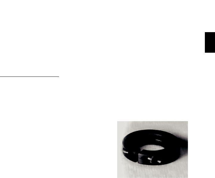
Bearings
This fan system uses bearings featuring concentric split locking collars. The collars are tightened through a cap screw bridging the split portion of the collar. The cap screw has a Torx T25 socket head. To tighten the locking collar: Hold the locking collar tightly against the inner race of the bearing and torque the cap screw to 65-70 in-lb (7.4-7.9 Nm). (See Fig. 7.)
C08121
Fig. 7 - Tightening Locking Collar
Motor
When replacing the motor, also replace the external-tooth lock washer (star washer) under the motor mounting base; this is part of the motor grounding system. Ensure the teeth on the lock washer are in contact with the motor’s painted base. Tighten motor mounting bolts to 120 +/- 12 in-lbs.
5
48TC
Changing fan wheel speed by changing pulleys: The horsepower rating of the belt is primarily dictated by the pitch diameter of the smaller pulley in the drive system (typically the motor pulley in these units). Do not install a replacement motor pulley with a smaller pitch diameter than provided on the original factory pulley. Change fan wheel speed by changing the fan pulley (larger pitch diameter to reduce wheel speed, smaller pitch diameter to increase wheel speed) or select a new system (both pulleys and matching belt(s)).
Before changing pulleys to increase fan wheel speed, check the fan performance at the target speed and airflow rate to determine new motor loading (bhp). Use the fan performance tables or use the Packaged Rooftop Builder software program. Confirm that the motor in this unit is capable of operating at the new operating condition. Fan shaft loading increases dramatically as wheel speed is increased.
To reduce vibration, replace the motor’s adjustable pitch pulley with a fixed pitch pulley (after the final airflow balance adjustment). This will reduce the amount of vibration generated by the motor/belt-drive system.
COOLING
!WARNING
UNIT OPERATION AND SAFETY HAZARD
Failure to follow this warning could cause personal injury, death and/or equipment damage.
This system uses PuronR refrigerant which has higher pressures than R-22 and other refrigerants. No other refrigerant may be used in this system. Gauge set, hoses, and recovery system must be designed to handle Puron refrigerant. If unsure about equipment, consult the equipment manufacturer.
Condenser Coil
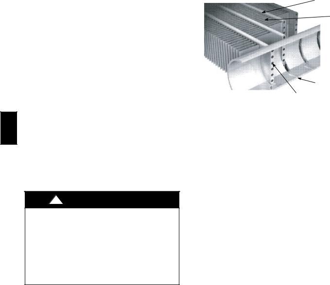
The condenser coil is new NOVATION Heat Exchanger Technology. This is an all-aluminum construction with louvered fins over single-depth crosstubes. The crosstubes have multiple small passages through which the refrigerant passes from header to header on each end. Tubes and fins are both aluminum construction. Connection tube joints are copper. The coil may be one-row or two-row. Two-row coils are spaced apart to assist in cleaning.
TUBES
FINS
MANIFOLD
MICROCHANNELS
C07273
Fig. 8 - Microchannel Coils
Evaporator Coil
The evaporator coil is traditional round-tube, plate-fin technology. Tube and fin construction is of various optional materials and coatings (see Model Number Format). Coils are multiple-row.
Coil Maintenance and Cleaning Recommendation
Routine cleaning of coil surfaces is essential to maintain proper operation of the unit. Elimination of contamination and removal of harmful residues will greatly increase the life of the coil and extend the life of the unit. The following maintenance and cleaning procedures are recommended as part of the routine maintenance activities to extend the life of the coil.
Remove Surface Loaded Fibers
Surface loaded fibers or dirt should be removed with a vacuum cleaner. If a vacuum cleaner is not available, a soft non-metallic bristle brush may be used. In either case, the tool should be applied in the direction of the fins. Coil surfaces can be easily damaged (fin edges can be easily bent over and damage to the coating of a protected coil) if the tool is applied across the fins.
NOTE: Use of a water stream, such as a garden hose, against a surface loaded coil will drive the fibers and dirt into the coil. This will make cleaning efforts more difficult. Surface loaded fibers must be completely removed prior to using low velocity clean water rinse.
Periodic Clean Water Rinse
A periodic clean water rinse is very beneficial for coils that are applied in coastal or industrial environments. However, it is very important that the water rinse is made with very low velocity water stream to avoid damaging the fin edges. Monthly cleaning as described below is recommended.
6

Routine Cleaning of NOVATION Condenser Coil Surfaces
To clean the NOVATION condenser coil, chemicals are NOT to be used; only water is approved as the cleaning solution. Only clean potable water is authorized for cleaning NOVATION condensers. Carefully remove any foreign objects or debris attached to the coil face or trapped within the mounting frame and brackets. Using a high pressure water sprayer, purge any soap or industial cleaners from hose and/or dilution tank prior to wetting the coil.
Clean condenser face by spraying the coil core steadily and uniformly from top to bottom, directing the spray straight into or toward the coil face. Do not exceed 900 psig or a 45 degree angle; nozzle must be at least 12 in. (30 cm) from the coil face. Reduce pressure and use caution to prevent damage to air centers (fins). Do not fracture the braze between air centers and refrigerant tubes. Allow water to drain from the coil core and check for refrigerant leaks prior to start-up.
NOTE: Please see the NOVATION Condenser Service section for specific information on the coil.
!CAUTION
PERSONAL INJURY HAZARD
Failure to follow this caution may result in personal injury or equipment damage.
Chemical cleaning should NOT be used on the aluminum NOVATION condenser. Damage to the coil may occur. Only approved cleaning is recommended.
Routine Cleaning of Evaporator Coil Sufaces
Monthly cleaning with Totaline® environmentally sound coil cleaner is essential to extend the life of coils. This cleaner is available from Carrier Replacement parts division as part number P902-0301 for one gallon container, and part number P902-0305 for a 5 gallon container. It is recommended that all round tube coil cleaner as described below. Coil cleaning should be part of the unit’s regularly scheduled maintenance procedures to ensure long life of the coil. Failure to clean the coils may result in reduced durability in the environment.
Avoid the use of S coil brighteners
S acid cleaning prior to painting S high pressure washers
S poor quality water for cleaning
Totaline environmentally sound coil cleaner is non-flammable, hypoallergenic, non-bacterial, and a USDA accepted biodegradable agent that will not harm coil or surrounding components such as electrical wiring, painted metal surfaces, or insulation. Use of non-recommended coil cleaners is strongly discouraged since coil and unit durability could be affected.
Totaline Environmentally Sound Coil Cleaner Application
Equipment
S 2-1/2 gallon garden sprayer
S water rinse with low velocity spray nozzle
!CAUTION
PERSONAL INJURY HAZARD
Failure to follow this caution may result in corrosion and damage to the unit.
Harsh chemicals, household bleach or acid or basic cleaners should not be used to clean outdoor or indoor coils of any kind. These cleaners can be very difficult to rinse out of the coil and can accelerate corrosion at the fin/tube interface where dissimilar materials are in contact. If there is dirt below the surface of the coil, use the Totaline environmentally sound coil cleaner as described above.
!CAUTION
PERSONAL INJURY HAZARD
Failure to follow this caution may result in reduced unit performance.
High velocity water from a pressure washer, garden hose, or compressed air should never be used to clean a coil. The force of the wter or air jet will bend the fin edges and icrease airside pressure drop.
Totaline Environmentally Sound Coil Cleaner application Instructions
1.Proper eye protection such as safety glasses is recommended during mixing and application.
2.Remove all surface loaded fibers and dirt with a vacuum cleaner as described above.
3.Thoroughly wet finned surfaces with clean water and a low velocity garden hose, being carefull not to bend fins.
4.Mix Totaline environmentally sound coil cleaner in a 2 1/2 gallon garden spryer according to the instructions included with the cleaner. The optimum solution temperature is 100°F (38°C).
NOTE: Do NOT USE water in excess of 130°F (54°C), as the enzymatic activity will be destroyed.
1.Thoroughly apply Totaline® environmentally sound coil cleaner solution to all coil surfaces including finned area, tube sheets and coil headers.
2.Hold garden sprayer nozzle close to finned areas and apply cleaner with a vertical, up-and-down motion. Avoid spraying in horizontal pattern to minimize potential for fin damage.
3.Ensure cleaner thoroughly penetrates deep into finned areas.
4.Interior and exterior finned areas must be thoroughly cleaned.
48TC
7

48TC
5.Finned surfaces should remain wet with cleaning solution for 10 minutes.
6.Ensure surfaces are not allowed to dry before rinsing. Reapply cleaner as needed to ensure 10-minute saturation is achieved.
7.Thoroghly rinse all surfaces with low velocity clean water using downward rinsing motion of water spray nozzle. Protect fins from damage from the spray nozzle.
Evaporator Coil Metering Devices
The metering devices are multiple fixed-bore devices (Acutrolt) swaged into the horizontal outlet tubes from the liquid header, located at the entrance to each evaporator coil circuit path. These are non-adjustable. Service requires replacing the entire liquid header assembly.
To check for possible blockage of one or more of these metering devices, disconnect the supply fan contactor (IFC) coil, then start the compressor and observe the frosting pattern on the face of the evaporator coil. A frost pattern should develop uniformly across the face of the coil starting at each horizontal header tube. Failure to develop frost at an outlet tube can indicate a plugged or a missing orifice.
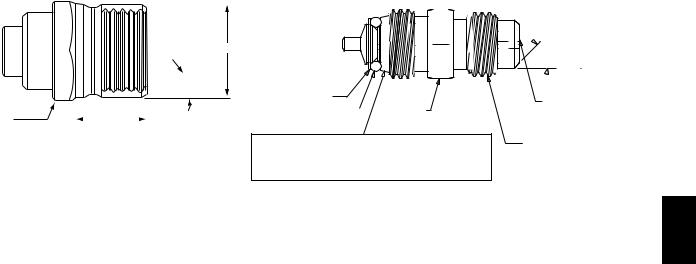
Refrigerant System Pressure Access Ports
There are two access ports in the system - on the suction tube near the compressor and on the discharge tube near the compressor. These are brass fittings with black plastic caps. The hose connection fittings are standard 1/4 SAE male flare couplings.
The brass fittings are two-piece High Flow valves, with a receptacle base brazed to the tubing and an integral spring-closed check valve core screwed into the base. (See Fig. 9.) This check valve is permanently assembled into this core body and cannot be serviced separately; replace the entire core body if necessary. Service tools are available from RCD that allow the replacement of the check valve core without having to recover the entire system refrigerant charge. Apply compressor refrigerant oil to the check valve core’s bottom O-ring. Install the fitting body with 96 +/- 10 in-lbs of torque; do not overtighten.
PURONR (R-410A) REFRIGERANT
This unit is designed for use with Puron (R-410A) refrigerant. Do not use any other refrigerant in this system.
Puron (R-410A) refrigerant is provided in pink (rose) colored cylinders. These cylinders are available with and without dip tubes; cylinders with dip tubes will have a label indicating this feature. For a cylinder with a dip tube, place the cylinder in the upright position (access valve at the top) when removing liquid refrigerant for charging. For a cylinder without a dip tube, invert the cylinder (access valve on the bottom) when removing liquid refrigerant.
Because Puron (R-410A) refrigerant is a blend, it is strongly recommended that refrigerant always be removed from the cylinder as a liquid. Admit liquid refrigerant into the system in the discharge line. If adding refrigerant into the suction line, use a commercial metering/expansion device at the gauge manifold; remove liquid from the cylinder, pass it through the metering device at the gauge set and then pass it into the suction line as a vapor. Do not remove Puron (R-410A) refrigerant from the cylinder as a vapor.
Refrigerant Charge
Amount of refrigerant charge is listed on the unit’s nameplate. Refer to Carrier GTAC2-5 Charging, Recovery, Recycling and Reclamation training manual and the following procedures.
Unit panels must be in place when unit is operating during the charging procedure. To prepare the unit for charge adjustment.
No Charge
Use standard evacuating techniques. After evacuating system, weigh in the specified amount of refrigerant.
Low-Charge Cooling
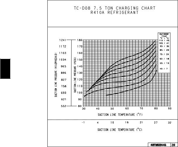
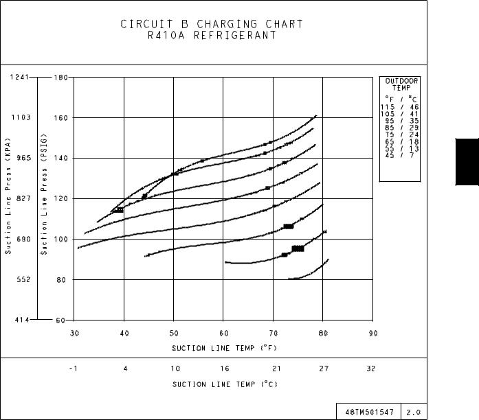
Using Cooling Charging Charts (Figs. 10, 11, 12, and 13), vary refrigerant until the conditions of the appropriate chart are met. Note the charging charts are different from the type normally used. Charts are based on charging the units to the correct superheat for the various operating conditions. Accurate pressure gauge and temperature sensing device are required. Connect the pressure gauge to the service port on the suction line. Mount the temperature sensing device on the suction line and insulate it so that outdoor ambient temperature does not affect the reading. Indoor-air cfm must be within the normal operating range of the unit.
To Use Cooling Charging Charts
Select the appropriate unit charging chart from Figs. 10, 11, 12, and 13.
S Sizes D08 and D12 each have one cooling charging chart
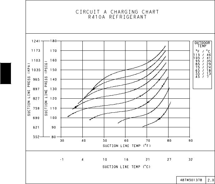
S Size D14 has two cooling charging charts: Circuit A and Circuit B
Take the outdoor ambient temperature and read the suction pressure gauge. Refer to chart to determine what suction temperature should be. If suction temperature is high, add refrigerant. If suction temperature is low, carefully recover some of the charge. Recheck the suction pressure as charge is adjusted.
For D14 size, perform this procedure once for Circuit A (using the Circuit A chart) and once for Circuit B (using the Circuit B chart).
8
SEAT |
CORE |
|||
|
|
(Part No. EC39EZ067) |
||
|
|
|
|
|
|
|
|
|
|
 1/2-20 UNF RH
0.596
 30o
30o
WASHER
|
|
|
|
|
|
O-RING |
|
1/2" HEX |
|
|
|
|
|
|
|
||
|
|
|
|
|
|
|
|
|
5/8” HEX |
|
|
.47 |
|
|
|||
|
|
|
|
|
|
|
This surface provides a metal to metal seal when torqued into the seat. Appropriate handling is required to not scratch or dent the surface.
Fig. 9 - CoreMax Access Port Assembly
EXAMPLE:
Model 48TC*D14
Circuit A:
Outdoor Temperature . . . . . . . . . . . . . . . . . . 85_F (29_C)
Suction Pressure . . . . . . . . . . . . . . . . . 125 psig (860 kPa)
Suction Temperature should be . . . . . . . . . . 58_F (14_C)
Circuit B:
Outdoor Temperature . . . . . . . . . . . . . . . . . . 85_F (29_C)
Suction Pressure . . . . . . . . . . . . . . . . . 120 psig (830 kPa)
Suction Temperature should be . . . . . . . . . . 60_F (16_C)
45o
DEPRESSOR PER ARI 720 +.01/-.035
FROM FACE OF BODY
7/16-20 UNF RH
C08453
48TC
9
COOLING CHARGING CHARTS
48TC
C08669
Fig. 10 - Cooling Charging Charts (D08)
10
COOLING CHARGING CHARTS
48TC
C08670
Fig. 11 - Cooling Charging Charts (D12)
11
COOLING CHARGING CHARTS
48TC
C09151
Fig. 12 - Cooling Charging Charts (D14 - Circuit A)
12
COOLING CHARGING CHARTS
48TC
C09152
Fig. 13 - Cooling Charging Charts (D14 - Circuit B)
13
Table 1 – Cooling Service Analysis
|
|
PROBLEM |
CAUSE |
REMEDY |
|
|
|
Power failure. |
Call power company. |
|
|
|
|
|
|
|
|
Fuse blown or circuit breaker tripped. |
Replace fuse or reset circuit breaker. |
|
|
|
|
|
|
|
Compressor and Condenser |
Defective thermostat, contactor, transformer, |
Replace component. |
|
|
or control relay. |
||
|
|
Fan Will Not Start. |
|
|
|
|
|
|
|
|
|
Insufficient line voltage. |
Determine cause and correct. |
|
|
|
|
||
|
|
|
|
|
|
|
|
Incorrect or faulty wiring. |
Check wiring diagram and rewire correctly. |
|
|
|
|
|
|
|
|
Thermostat setting too high. |
Lower thermostat setting below room temperature. |
|
|
|
Faulty wiring or loose connections in |
Check wiring and repair or replace. |
|
|
|
compressor circuit. |
|
|
|
|
|
|
|
|
|
|
|
|
|
|
Compressor motor burned out, seized, or |
Determine cause. Replace compressor. |
|
|
Compressor Will Not Start But |
internal overload open. |
|
|
|
|
||
|
|
Condenser Fan Runs. |
|
|
|
|
Defective run/start capacitor, overload, start |
Determine cause and replace. |
|
|
|
|
relay. |
|
|
|
|
|
|
|
|
|
|
|
|
|
|
One leg of three---phase power dead. |
Replace fuse or reset circuit breaker. Determine |
|
|
|
||
48TC |
|
|
cause. |
|
|
|
|
||
|
|
|
to nameplate. |
|
|
|
|
Refrigerant overcharge or undercharge. |
Recover refrigerant, evacuate system, and recharge |
|
|
|
|
|
|
|
|
|
|
|
|
|
Defective compressor. |
Replace and determine cause. |
|
|
|
|
|
|
|
Compressor Cycles (other |
Insufficient line voltage. |
Determine cause and correct. |
|
|
|
|
|
|
|
Blocked condenser. |
Determine cause and correct. |
|
|
|
than normally satisfying |
||
|
|
|
|
|
|
|
Defective run/start capacitor, overload, or start |
|
|
|
|
thermostat). |
Determine cause and replace. |
|
|
|
relay. |
||
|
|
|
|
|
|
|
|
|
|
|
|
|
Defective thermostat. |
Replace thermostat. |
|
|
|
|
|
|
|
|
Faulty condenser---fan motor or capacitor. |
Replace. |
|
|
|
|
|
|
|
|
Restriction in refrigerant system. |
Locate restriction and remove. |
|
|
|
Dirty air filter. |
Replace filter. |
|
|
|
|
|
|
|
|
Unit undersized for load. |
Decrease load or increase unit size. |
|
|
|
|
|
|
|
Compressor Operates |
Thermostat set too low. |
Reset thermostat. |
|
|
|
|
|
|
|
Low refrigerant charge. |
Locate leak; repair and recharge. |
|
|
|
Continuously. |
||
|
|
|
|
|
|
|
Leaking valves in compressor. |
Replace compressor. |
|
|
|
|
||
|
|
|
Air in system. |
Recover refrigerant, evacuate system, and recharge. |
|
|
|
|
|
|
|
|
Condenser coil dirty or restricted. |
Clean coil or remove restriction. |
|
|
|
|
|
|
|
|
Dirty air filter. |
Replace filter. |
|
|
|
Dirty condenser coil. |
Clean coil. |
|
|
Excessive Head Pressure. |
|
|
|
|
Refrigerant overcharged. |
Recover excess refrigerant. |
|
|
|
|
|
|
|
|
|
Air in system. |
Recover refrigerant, evacuate system, and recharge. |
|
|
|
Condenser air restricted or air short---cycling. |
Determine cause and correct. |
|
|
|
|
|
|
|
|
Low refrigerant charge. |
Check for leaks; repair and recharge. |
|
|
Head Pressure Too Low. |
|
|
|
|
Compressor valves leaking. |
Replace compressor. |
|
|
|
|
|
|
|
|
|
Restriction in liquid tube. |
Remove restriction. |
|
|
|
|
|
|
|
|
High head load. |
Check for source and eliminate. |
|
|
Excessive Suction Pressure. |
|
|
|
|
Compressor valves leaking. |
Replace compressor. |
|
|
|
|
|
|
|
|
|
Refrigerant overcharged. |
Recover excess refrigerant. |
|
|
|
|
|
|
|
|
Dirty air filter. |
Replace filter. |
|
|
|
Low refrigerant charge. |
Check for leaks; repair and recharge. |
|
|
|
|
|
|
|
|
Metering device or low side restricted. |
Remove source of restriction. |
|
|
Suction Pressure Too Low. |
|
|
|
|
Insufficient evaporator airflow. |
Increase air quantity. Check filter and replace if |
|
|
|
|
necessary. |
|
|
|
|
|
|
|
|
|
|
|
|
|
|
Temperature too low in conditioned area. |
Reset thermostat. |
|
|
|
|
|
|
|
|
Outdoor ambient below 25° F. |
Install low---ambient kit. |
|
|
|
|
|
|
|
Evaporator Fan Will Not Shut |
Time off delay not finished. |
Wait for 30---second off delay. |
|
|
Off. |
||
|
|
|
|
|
|
|
|
|
|
|
|
Compressor Makes Excessive |
Compressor rotating in wrong direction. |
Reverse the 3---phase power leads. |
|
|
Noise. |
||
|
|
|
|
|
|
|
|
|
|
14
Compressors
Lubrication
Compressors are charged with the correct amount of oil at the factory.
!CAUTION
UNIT DAMAGE HAZARD
Failure to follow this caution may result in damage to components.
The compressor is in a PuronR refrigerant system and uses a polyolester (POE) oil. This oil is extremely hygroscopic, meaning it absorbs water readily. POE oils can absorb 15 times as much water as other oils designed for HCFC and CFC refrigerants. Avoid exposure of the oil to the atmosphere.
!WARNING
PERSONAL INJURY AND ENVIRONMENTAL HAZARD
Failure to follow this warning could result in personal injury or death.
Relieve pressure and recover all refrigerant before system repair or final unit disposal.
Wear safety glasses and gloves when handling refrigerants.
Keep torches and other ignition sources away from refrigerants and oils.
Replacing Compressor
The compressor used with Puron refrigerant contains a POE oil. This oil has a high affinity for moisture. Do not remove the compressor’s tube plugs until ready to insert the unit suction and discharge tube ends.
Compressor mounting bolt torque is 65-75 in-lbs (7.3-8.5 N-m).
Compressor Rotation
On 3-phase units with scroll compressors, it is important to be certain compressor is rotating in the proper direction. To determine whether or not compressor is rotating in the proper direction:
1.Connect service gauges to suction and discharge pressure fittings.
2.Energize the compressor.
3.The suction pressure should drop and the discharge pressure should rise, as is normal on any start-up.
NOTE: If the suction pressure does not drop and the discharge pressure does not rise to normal levels:
4.Note that the evaporator fan is probably also rotating in the wrong direction.
5.Turn off power to the unit.
6.Reverse any two of the unit power leads.
7.Reapply power to the compressor.
The suction and discharge pressure levels should now |
|
||||||||||||||||||||||||||
move to their normal start-up levels. |
|
||||||||||||||||||||||||||
NOTE: When the compressor is rotating in the wrong |
|
||||||||||||||||||||||||||
direction, the unit makes an elevated level of noise and |
|
||||||||||||||||||||||||||
does not provide cooling. |
|
||||||||||||||||||||||||||
Filter Drier |
|
||||||||||||||||||||||||||
Replace whenever refrigerant system is exposed to |
|
||||||||||||||||||||||||||
atmosphere. Only use factory specified liquid-line filter |
|
||||||||||||||||||||||||||
driers with working pressures no less than 650 psig. Do |
|
||||||||||||||||||||||||||
not install a suction-line filter drier in liquid line. A |
|
||||||||||||||||||||||||||
liquid-line filter drier designed for use with Puron |
|
||||||||||||||||||||||||||
refrigerant is required on every unit. |
|
||||||||||||||||||||||||||
48TC |
|||||||||||||||||||||||||||
Condenser-Fan Adjustment (D08-D12 size) |
|||||||||||||||||||||||||||
1. |
Shut off unit power supply. Install lockout tag. |
||||||||||||||||||||||||||
2. |
Remove condenser-fan assembly (grille, motor, and |
|
|||||||||||||||||||||||||
|
|||||||||||||||||||||||||||
|
|
fan). |
|
||||||||||||||||||||||||
3. |
Loosen fan hub setscrews. |
|
|||||||||||||||||||||||||
4. |
Adjust fan height as shown in Fig. 14. |
|
|||||||||||||||||||||||||
5. |
Tighten setscrews to 84 in-lbs (9.5 N-m). |
|
|||||||||||||||||||||||||
6. |
Replace condenser-fan assembly. |
|
|||||||||||||||||||||||||
|
|
|
|
|
|
|
|
|
|
|
|
|
|
|
|
|
|
|
|
|
|
|
|
|
|
|
|
|
|
|
|
|
|
|
|
|
|
|
|
|
|
|
|
|
|
|
|
|
|
|
|
|
|
|
|
|
|
|
|
|
|
|
|
|
|
|
|
|
|
|
|
|
|
|
|
|
|
|
|
|
|
|
|
|
|
|
|
|
|
|
|
|
|
|
|
|
|
|
|
|
|
|
|
|
|
|
|
|
|
|
|
|
|
|
|
|
|
|
|
|
|
|
|
|
|
|
|
|
|
|
|
|
|
|
|
|
|
|
|
|
|
|
|
|
|
|
|
|
|
|
|
|
|
|
|
|
|
|
|
|
|
|
|
|
|
|
|
|
|
|
|
|
|
|
|
|
|
|
|
|
|
|
|
|
|
|
|
|
|
|
|
|
|
|
|
|
|
|
|
|
|
|
|
|
|
|
|
|
|
|
|
|
|
|
|
|
|
|
|
|
|
|
|
CONDUIT
0.14 in +0.0/-0.03
C08448
Fig. 14 - Condenser Fan Adjustment (D08-D12)
Condenser-Fan Adjustment (D14 size)
1.Shut off unit power supply. Install lockout tag.
2.Remove condenser fan grille.
3.Loosen fan hub setscrews.
4.Adjust fan height as shown in Fig. 15.
5.Tighten setscrews to 84 in-lbs (9.5 N-m).
6.Replace fan grille.
C09094
Fig. 15 - Condenser Fan Adjustment (D14)
Troubleshooting Cooling System
Refer to Table 1 for additional troubleshooting topics.
15

CONVENIENCE OUTLETS
|
|
! |
WARNING |
|
|
|
ELECTRICAL OPERATION HAZARD |
|
|
|
|
Failure to follow this warning could result in personal |
|
|
|
|
injury or death. |
|
|
|
|
Units with convenience outlet circuits may use |
|
|
|
|
multiple disconnects. Check convenience outlet for |
|
|
|
|
power status before opening unit for service. Locate |
|
|
|
|
its disconnect |
switch, if appropriate, and open it. |
|
|
|
Tag-out this switch, if necessary. |
|
|
|
|
|
|
|
|
|
Two types of convenience outlets are offered on 48TC |
||
|
|
models: Non-powered and unit-powered. Both types |
||
48TC |
|
|||
|
provide a 125-volt GFCI (ground-fault circuit-interrupter) |
|||
|
duplex receptacle rated at 15-A behind a hinged |
|||
|
|
|||
|
|
waterproof access cover, located on the end panel of the |
||
|
|
unit. (See Fig. 16.) |
||
|
|
|||
Pwd-CO Transformer
Conv Outlet
GFCI
Pwd-CO
Fuse 
Switch
C08128
Fig. 16 - Convenience Outlet Location
Non-Powered Type
This type requires the field installation of a general-purpose 125-volt 15-A circuit powered from a source elsewhere in the building. Observe national and local codes when selecting wire size, fuse or breaker requirements and disconnect switch size and location. Route 125-v power supply conductors into the bottom of the utility box containing the duplex receptacle.
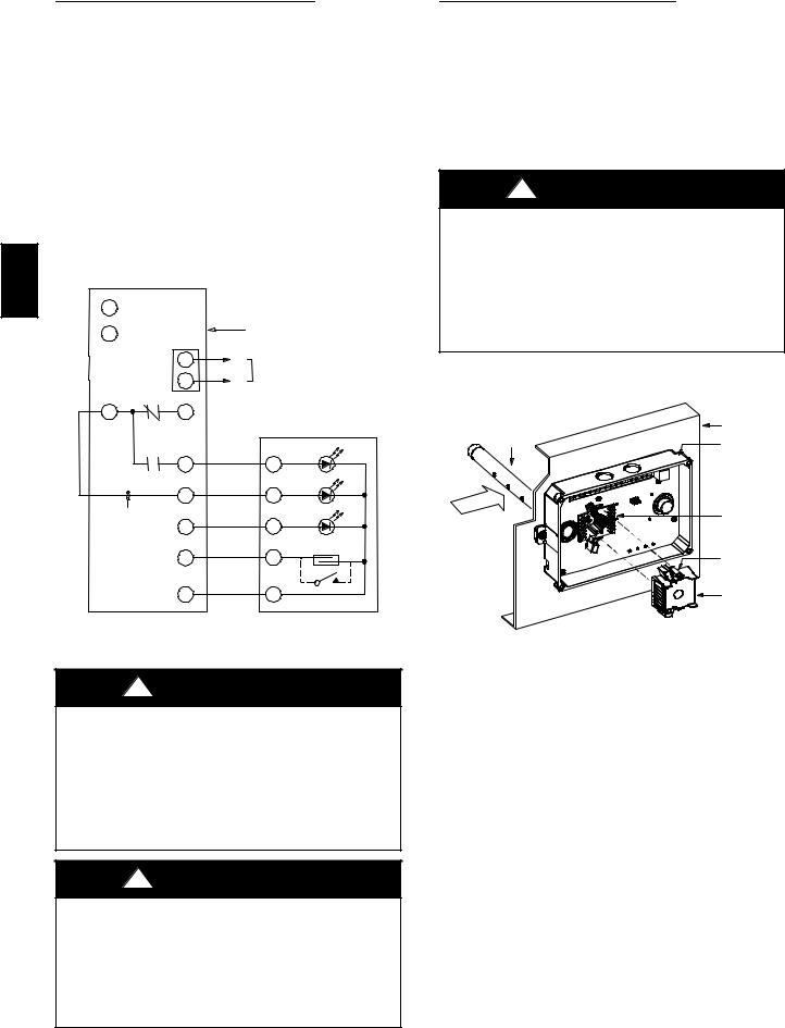
Unit-Powered Type
A unit-mounted transformer is factory-installed to stepdown the main power supply voltage to the unit to 115-v at the duplex receptacle. This option also includes a manual switch with fuse, located in a utility box and mounted on a bracket behind the convenience outlet; access is through the unit’s control box access panel. (See Fig. 16.)
The primary leads to the convenience outlet transformer are not factory-connected. Selection of primary power source is a customer-option. If local codes permit, the transformer primary leads can be connected at the line-side terminals on a unit-mounted non-fused disconnect or circuit-breaker switch; this will provide service power to the unit when the unit disconnect switch or circuit-breaker is open. Other connection methods will result in the convenience outlet circuit being de-energized when the unit disconnect or circuit-breaker is open. (See Fig. 17.)
CO8283 |
Fig. 17 - Powered Convenience Outlet Wiring
UNIT |
CONNECT |
PRIMARY |
TRANSFORMER |
|
VOLTAGE |
AS |
CONNECTIONS |
TERMINALS |
|
|
|
|
|
|
208, |
240 |
L1: RED +YEL |
H1 + H3 |
|
230 |
L2: BLU + GRA |
H2 + H4 |
||
|
||||
|
|
|
|
|
|
|
L1: RED |
H1 |
|
460 |
480 |
Splice BLU + YEL |
H2 + H3 |
|
|
|
L2: GRA |
H4 |
|
|
|
|
|
|
575 |
600 |
L1: RED |
H1 |
|
L2: GRA |
H2 |
|||
|
|
|||
|
|
|
|
Duty Cycle
The unit-powered convenience outlet has a duty cycle limitation. The transformer is intended to provide power on an intermittent basis for service tools, lamps, etc; it is not intended to provide 15-amps loading for continuous duty loads (such as electric heaters for overnight use). Observe a 50% limit on circuit loading above 8-amps (i.e., limit loads exceeding 8-amps to 30 minutes of operation every hour).
16
Maintenance
Periodically test the GFCI receptacle by pressing the TEST button on the face of the receptacle. This should cause the internal circuit of the receptacle to trip and open the receptacle. Check for proper grounding wires and power line phasing if the GFCI receptacle does not trip as required. Press the RESET button to clear the tripped condition.
Fuse On Powered Type
The factory fuse is a Bussman “Fusetron” T-15, non-renewable screw-in (Edison base) type plug fuse.
Using Unit-Mounted Convenience Outlets
Units with unit-mounted convenience outlet circuits will often require that two disconnects be opened to de-energize all power to the unit. Treat all units as electrically energized until the convenience outlet power is also checked and de-energization is confirmed. Observe National Electrical Code Article 210, Branch Circuits, for use of convenience outlets.
SMOKE DETECTORS
Smoke detectors are available as factory-installed options on 48TC models. Smoke detectors may be specified for Supply Air only or for Return Air without or with economizer or in combination of Supply Air and Return Air. Return Air smoke detectors are arranged for vertical return configurations only. All components necessary for operation are factory-provided and mounted. The unit is factory-configured for immediate smoke detector shutdown operation; additional wiring or modifications to unit terminal board may be necessary to complete the unit and smoke detector configuration to meet project requirements.
System
The smoke detector system consists of a four-wire controller and one or two sensors. Its primary function is to shut down the rooftop unit in order to prevent smoke from circulating throughout the building. It is not to be used as a life saving device.
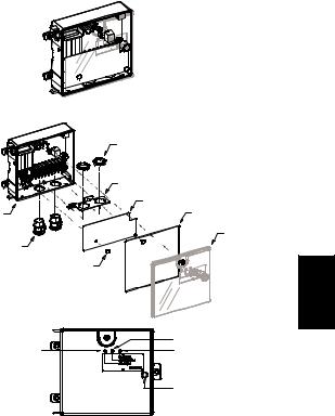
Controller
The controller (see Fig. 18) includes a controller housing, a printed circuit board, and a clear plastic cover. The controller can be connected to one or two compatible duct smoke sensors. The clear plastic cover is secured to the housing with a single captive screw for easy access to the wiring terminals. The controller has three LEDs (for Power, Trouble and Alarm) and a manual test/reset button (on the cover face).
Duct smoke sensor
|
controller |
|
Conduit nuts |
|
(supplied by installer) |
|
Conduit support plate |
|
Terminal block cover |
Controller housing |
Cover gasket |
and electronics |
(ordering option) |
Conduit couplings |
Controller cover |
|
|
(supplied by installer) |
|
|
Fastener |
|
(2X) |
|
Trouble |
Alarm |
Power |
|
Test/reset |
|
switch |
C08208
Fig. 18 - Controller Assembly
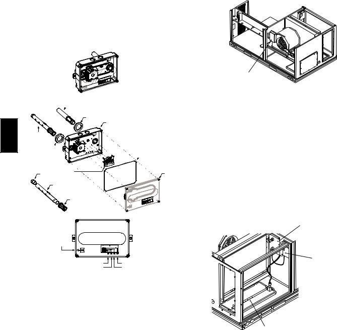
Sensor
The sensor (see Fig. 19) includes a plastic housing, a printed circuit board, a clear plastic cover, a sampling tube inlet and an exhaust tube. The sampling tube (when used) and exhaust tube are attached during installation. The sampling tube varies in length depending on the size of the rooftop unit. The clear plastic cover permits visual inspections without having to disassemble the sensor. The cover attaches to the sensor housing using four captive screws and forms an airtight chamber around the sensing electronics. Each sensor includes a harness with an RJ45 terminal for connecting to the controller. Each sensor has four LEDs (for Power, Trouble, Alarm and Dirty) and a manual test/reset button (on the left-side of the housing).
Air is introduced to the duct smoke detector sensor’s sensing chamber through a sampling tube that extends into the HVAC duct and is directed back into the ventilation system through a (shorter) exhaust tube. The difference in air pressure between the two tubes pulls the sampled air through the sensing chamber. When a sufficient amount of smoke is detected in the sensing chamber, the sensor signals an alarm state and the controller automatically takes the appropriate action to shut down fans and blowers, change over air handling systems, notify the fire alarm control panel, etc.
48TC
17
The sensor uses a process called differential sensing to prevent gradual environmental changes from triggering false alarms. A rapid change in environmental conditions, such as smoke from a fire, causes the sensor to signal an alarm state but dust and debris accumulated over time does not.
Duct smoke sensor
 Exhaust tube
Exhaust gasket
Sensor housing and electronics
48TC |
See |
|
Detail A |
Intake 
gasket
Cover gasket  (ordering option)
|
TSD-CO2 |
|
(ordering option) |
Plug |
Sensor cover |
|
Sampling tube |
|
(ordered separately) |
Detail A |
Coupling |
|
Magnetic test/reset switch
Alarm |
Power |
Trouble |
Dirty |
C08209
Fig. 19 - Smoke Detector Sensor
For installations using two sensors, the duct smoke detector does not differentiate which sensor signals an alarm or trouble condition.
Smoke Detector Locations
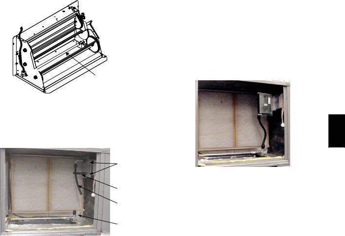
Supply Air — The Supply Air smoke detector sensor is located to the left of the unit’s indoor (supply) fan. (See Fig. 20.) Access is through the fan access panel. There is no sampling tube used at this location. The sampling tube inlet extends through the side plate of the fan housing (into a high pressure area). The controller is located on a bracket to the right of the return filter, accessed through the lift-off filter panel.
Smoke Detector Sensor
C08245
Fig. 20 - Typical Supply Air Smoke Detector Sensor
Location
Return Air without Economizer — The sampling tube is located across the return air opening on the unit basepan. (See Fig. 21.) The holes in the sampling tube face downward, into the return air stream. The sampling tube is connected via tubing to the return air sensor that is mounted on a bracket high on the partition between return filter and controller location. (This sensor is shipped in a flat-mounting location. Installation requires that this sensor be relocated to its operating location and the tubing to the sampling tube be connected. See installation steps below.)
Return Air Detector module (shipping position shown)*
Controller module
Return Air Detector Sampling Tube
*RA detector must be moved from shipping position to operating position by installer
C07307
Fig. 21 - Typical Return Air Detector Location
Return Air with Economizer — The sampling tube is inserted through the side plates of the economizer housing, placing it across the return air opening on the unit basepan. (See Fig. 22.) The holes in the sampling tube face downward, into the return air stream. The sampling tube is connected via tubing to the return air sensor that is mounted on a bracket high on the partition between return filter and controller location. (This sensor is shipped in a flat-mounting location. Installation requires that this sensor be relocated to its operating location and the tubing to the sampling tube be connected. See installation steps below.)
18
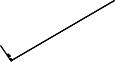
 Return Air
Sampling Tube
C08129
Fig. 22 - Return Air Sampling Tube Location
Completing Installation of Return Air Smoke
Sensor:
SCREWS
EXHAUST
TUBE
FLEXIBLE
EXTENSION
TUBE
SAMPLING
C08126
Fig. 23 - Return Air Detector Shipping Position
1.Unscrew the two screws holding the Return Air Sensor detector plate. (See Fig. 23.) Save the screws.
2.Remove the Return Air Sensor and its detector plate.
3.Rotate the detector plate so the sensor is facing outwards and the sampling tube connection is on the bottom. (See Fig. 24.)
4.Screw the sensor and detector plate into its operating position using screws from Step 1. Make sure the sampling tube connection is on the bottom and the exhaust tube is on the top. (See Fig. 23.)
5.Connect the flexible tube on the sampling inlet to the sampling tube on the basepan.
6.For units with an economizer, the sampling tube is integrated into the economizer housing but the connection of the flexible tubing to the sampling tube is the same.
48TC
C08127
Fig. 24 - Return Air Sensor Operating Position
FIOP Smoke Detector Wiring and Response
All units: FIOP smoke detector is configured to automatically shut down all unit operations when smoke condition is detected. See Fig. 25, Smoke Detector Wiring.
Highlight A: JMP 3 is factory-cut, transferring unit control to smoke detector.
Highlight B: Smoke detector NC contact set will open on smoke alarm condition, de-energizing the ORN conductor.
19

48TC
B
D
C
 F
F
E
A
C08246
Fig. 25 - Typical Smoke Detector System Wiring
Highlight C: 24-v power signal via ORN lead is removed at Smoke Detector input on LCTB; all unit operations cease immediately.
PremierLinkt and RTU-MP Controls: Unit operating functions (fan, cooling and heating) are terminated as described above. In addition:
Highlight D: On smoke alarm condition, the smoke detector NO Alarm contact will close, supplying 24-v power to GRA conductor.
Highlight E: GRA lead at Smoke Alarm input on LCTB provides 24-v signal to FIOP DDC control.
PremierLink: This signal is conveyed to PremierLink FIOP’s TB1 at terminal TB1-6 (BLU lead). This signal initiates the FSD sequence by the PremierLink control. FSD status is reported to connected CCN network.
RTU-MP: The 24-v signal is conveyed to RTU-MP’s J1-10 input terminal. This signal initiates the FSD sequence by the RTU-MP control. FSD status is reported to connected BAS network.
Using Remote Logic: Five conductors are provided for field use (see Highlight F) for additional annunciation functions.
Additional Application Data — Refer to Catalog No. HKRNKA-1XA for discussions on additional control features of these smoke detectors including multiple unit coordination. (See Fig. 25.)
Sensor and Controller Tests
Sensor Alarm Test
The sensor alarm test checks a sensor’s ability to signal an alarm state. This test requires that you use a field provided SD-MAG test magnet.
!CAUTION
OPERATIONAL TEST HAZARD
Failure to follow this caution may result in personnel and authority concern.
This test places the duct detector into the alarm state. Unless part of the test, disconnect all auxiliary equipment from the controller before performing the test. If the duct detector is connected to a fire alarm system, notify the proper authorities before performing the test.
Sensor Alarm Test Procedure
1.Hold the test magnet where indicated on the side of the sensor housing for seven seconds.
2.Verify that the sensor’s Alarm LED turns on.
3.Reset the sensor by holding the test magnet against the sensor housing for two seconds.
4.Verify that the sensor’s Alarm LED turns off.
Controller Alarm Test
The controller alarm test checks the controller’s ability to initiate and indicate an alarm state.
20
!CAUTION
OPERATIONAL TEST HAZARD
Failure to follow this caution may result in personnel and authority concern.
This test places the duct detector into the alarm state. Disconnect all auxiliary equipment from the controller before performing the test. If the duct detector is connected to a fire alarm system, notify the proper authorities before performing the test.
Controller Alarm Test Procedure
1.Press the controller’s test/reset switch for seven seconds.
2.Verify that the controller’s Alarm LED turns on.
3.Reset the sensor by pressing the test/reset switch for two seconds.
4.Verify that the controller’s Alarm LED turns off.
Dirty Controller Test
The dirty controller test checks the controller’s ability to initiate a dirty sensor test and indicate its results.
!CAUTION
OPERATIONAL TEST HAZARD
Failure to follow this caution may result in personnel and authority concern.
Pressing the controller’s test/reset switch for longer than seven seconds will put the duct detector into the alarm state and activate all automatic alarm responses.
Dirty Controller Test Procedure
S Press the controller’s test/reset switch for two seconds. S Verify that the controller’s Trouble LED flashes.
Dirty Sensor Test
The dirty sensor test provides an indication of the sensor’s ability to compensate for gradual environmental changes. A sensor that can no longer compensate for environmental changes is considered 100% dirty and requires cleaning or replacing. You must use a field provided SD-MAG test magnet to initiate a sensor dirty test. The sensor’s Dirty LED indicates the results of the dirty test as shown in Table 2.
!CAUTION
OPERATIONAL TEST HAZARD
Failure to follow this caution may result in personnel and authority concern.
Holding the test magnet against the sensor housing for more than seven seconds will put the duct detector into the alarm state and activate all automatic alarm responses.
|
Table 2 – Dirty LED Test |
|
|
FLASHES |
DESCRIPTION |
|
|
1 |
0---25% dirty. (Typical of a newly installed detector) |
|
|
2 |
25---50% dirty |
|
|
3 |
51---75% dirty |
|
|
4 |
76---99% dirty |
|
|
Dirty Sensor Test Procedure
1.Hold the test magnet where indicated on the side of the sensor housing for two seconds.
2.Verify that the sensor’s Dirty LED flashes.
!CAUTION
OPERATIONAL TEST HAZARD
Failure to follow this caution may result in personnel and authority concern.
Changing the dirty sensor test operation will put the detector into the alarm state and activate all automatic alarm responses. Before changing dirty sensor test operation, disconnect all auxiliary equipment from the controller and notify the proper authorities if connected to a fire alarm system.
Changing the Dirty Sensor Test
By default, sensor dirty test results are indicated by:
S The sensor’s Dirty LED flashing.
S The controller’s Trouble LED flashing.
S The controller’s supervision relay contacts toggle.
The operation of a sensor’s dirty test can be changed so that the controller’s supervision relay is not used to indicate test results. When two detectors are connected to a controller, sensor dirty test operation on both sensors must be configured to operate in the same manner.
To Configure the Dirty Sensor Test Operation
1.Hold the test magnet where indicated on the side of the sensor housing until the sensor’s Alarm LED turns on and its Dirty LED flashes twice (approximately 60 seconds).
2.Reset the sensor by removing the test magnet then holding it against the sensor housing again until the sensor’s Alarm LED turns off (approximately 2 seconds).
Remote Station Test
The remote station alarm test checks a test/reset station’s ability to initiate and indicate an alarm state.
!CAUTION
OPERATIONAL TEST HAZARD
Failure to follow this caution may result in personnel and authority concern.
This test places the duct detector into the alarm state. Unless part of the test, disconnect all auxiliary equipment from the controller before performing the test. If the duct detector is connected to a fire alarm system, notify the proper authorities before performing the test.
48TC
21
48TC
SD-TRK4 Remote Alarm Test Procedure
1.Turn the key switch to the RESET/TEST position for seven seconds.
2.Verify that the test/reset station’s Alarm LED turns on.
3.Reset the sensor by turning the key switch to the RESET/TEST position for two seconds.
4.Verify that the test/reset station’s Alarm LED turns off.
Remote Test/Reset Station Dirty Sensor Test
The test/reset station dirty sensor test checks the test/reset station’s ability to initiate a sensor dirty test and indicate the results. It must be wired to the controller as shown in Fig. 26 and configured to operate the controller’s supervision relay. For more information, see “Changing the Dirty Sensor Test.”
12 |
|
|
|
|
|
1 |
|
|
|
|
Smoke Detector Controller |
|
TB3 |
|
|
|
|
|
|
|
|
|
|
|
|
1 |
− |
|
Auxiliary |
|
|
|
|
|
|
|
|
2 |
+ |
|
equipment |
|
|
|
|
||
3 |
|
14 |
|
|
|
|
Supervision relay |
|
|
SD-TRK4 |
|
|
|
|
|
||
|
contacts [3] |
|
|
Trouble |
|
|
|
|
|
|
|
|
|
13 |
|
|
5 |
|
|
|
18 Vdc ( |
+) |
Power |
|
|
19 |
4 |
||
|
|
|
|
||
Wire must be |
|
|
|
Alarm |
|
added by installer |
15 |
|
|
1 |
|
|
|
|
|
||
|
|
|
|
|
Reset/Test |
23
18 Vdc ( |
−) |
20 |
2 |
C08247
Fig. 26 - Remote Test/Reset Station Connections
!CAUTION
OPERATIONAL TEST HAZARD
Failure to follow this caution may result in personnel and authority concern.
If the test/reset station’s key switch is left in the RESET/TEST position for longer than seven seconds, the detector will automatically go into the alarm state and activate all automatic alarm responses.
!CAUTION
OPERATIONAL TEST HAZARD
Failure to follow this caution may result in personnel and authority concern.
Holding the test magnet to the target area for longer than seven seconds will put the detector into the alarm state and activate all automatic alarm responses.
Dirty Sensor Test Using an SD-TRK4
1.Turn the key switch to the RESET/TEST position for two seconds.
2.Verify that the test/reset station’s Trouble LED flashes.
Detector Cleaning
Cleaning the Smoke Detector
Clean the duct smoke sensor when the Dirty LED is flashing continuously or sooner if conditions warrant.
!CAUTION
OPERATIONAL TEST HAZARD
Failure to follow this caution may result in personnel and authority concern.
If the smoke detector is connected to a fire alarm system, first notify the proper authorities that the detector is undergoing maintenance then disable the relevant circuit to avoid generating a false alarm.
1.Disconnect power from the duct detector then remove the sensor’s cover. (See Fig. 27.)
Sampling |
HVAC duct |
|
tube |
Sensor |
|
|
||
|
housing |
|
Airflow |
Optic |
|
plate |
||
|
||
|
Retainer |
|
|
clip |
|
|
Optic |
|
|
housing |
|
|
C07305 |
Fig. 27 - Sensor Cleaning Diagram
2.Using a vacuum cleaner, clean compressed air, or a soft bristle brush, remove loose dirt and debris from inside the sensor housing and cover.
Use isopropyl alcohol and a lint-free cloth to remove dirt and other contaminants from the gasket on the sensor’s cover.
3.Squeeze the retainer clips on both sides of the optic housing then lift the housing away from the printed circuit board.
4.Gently remove dirt and debris from around the optic plate and inside the optic housing.
5.Replace the optic housing and sensor cover.
6.Connect power to the duct detector then perform a sensor alarm test.
22
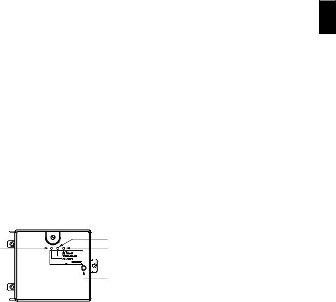
INDICATORS
Normal State
The smoke detector operates in the normal state in the absence of any trouble conditions and when its sensing chamber is free of smoke. In the normal state, the Power LED on both the sensor and the controller are on and all other LEDs are off.
Alarm State
The smoke detector enters the alarm state when the amount of smoke particulate in the sensor’s sensing chamber exceeds the alarm threshold value. (See Table 3.) Upon entering the alarm state:
SThe sensor’s Alarm LED and the controller’s Alarm LED turn on.
S The contacts on the controller’s two auxiliary relays switch positions.
S The contacts on the controller’s alarm initiation relay close.
S The controller’s remote alarm LED output is activated (turned on).
S The controller’s high impedance multiple fan shutdown control line is pulled to ground Trouble state.
The SuperDuct duct smoke detector enters the trouble state under the following conditions:
S A sensor’s cover is removed and 20 minutes pass before it is properly secured.
S A sensor’s environmental compensation limit is reached (100% dirty).
S A wiring fault between a sensor and the controller is detected.
An internal sensor fault is detected upon entering the trouble state:
S The contacts on the controller’s supervisory relay switch positions. (See Fig. 28.)
S If a sensor trouble, the sensor’s Trouble LED the controller’s Trouble LED turn on.
S If 100% dirty, the sensor’s Dirty LED turns on and the controller’s Trouble LED flashes continuously.
S If a wiring fault between a sensor and the controller, the controller’s Trouble LED turns on but not the sensor’s.
|
Trouble |
Alarm |
Power |
|
Test/reset |
|
switch |
|
C07298 |
Fig. 28 - Controller Assembly
NOTE: All troubles are latched by the duct smoke detector. The trouble condition must be cleared and then the duct smoke detector must be reset in order to restore it to the normal state.
Resetting Alarm and Trouble Condition Trips:
Manual reset is required to restore smoke detector systems to Normal operation. For installations using two sensors, the duct smoke detector does not differentiate which sensor signals an alarm or trouble condition. Check each sensor for Alarm or Trouble status (indicated by LED). Clear the condition that has generated the trip at this sensor. Then reset the sensor by pressing and holding the reset button (on the side) for 2 seconds. Verify that the sensor’s Alarm and Trouble LEDs are now off. At the controller, clear its Alarm or Trouble state by pressing and holding the manual reset button (on the front cover) for 2 seconds. Verify that the controller’s Alarm and Trouble LEDs are now off. Replace all panels.
Troubleshooting
Controller’s Trouble LED is On
1.Check the Trouble LED on each sensor connected to the controller. If a sensor’s Trouble LED is on, determine the cause and make the necessary repairs.
2.Check the wiring between the sensor and the controller. If wiring is loose or missing, repair or replace as required.
Controller’s Trouble LED is Flashing
1.One or both of the sensors is 100% dirty.
2.Determine which Dirty LED is flashing then clean that sensor assembly as described in the detector cleaning section.
Sensor’s Trouble LED is On
1.Check the sensor’s Dirty LED. If it is flashing, the sensor is dirty and must be cleaned.
2.Check the sensor’s cover. If it is loose or missing, secure the cover to the sensor housing.
3.Replace sensor assembly.
Sensor’s Power LED is Off
1.Check the controller’s Power LED. If it is off, determine why the controller does not have power and make the necessary repairs.
2.Check the wiring between the sensor and the controller. If wiring is loose or missing, repair or replace as required.
48TC
23

48TC
|
Table 3 – Detector Indicators |
|
|
|
|
CONTROL OR INDICATOR |
DESCRIPTION |
|
Magnetic test/reset switch |
Resets the sensor when it is in the alarm or trouble state. Activates or tests the sensor when it is in |
|
the normal state. |
||
|
||
|
|
|
Alarm LED |
Indicates the sensor is in the alarm state. |
|
|
|
|
Trouble LED |
Indicates the sensor is in the trouble state. |
|
|
|
|
Dirty LED |
Indicates the amount of environmental compensation used by the sensor |
|
(flashing continuously = 100%) |
||
|
||
|
|
|
Power LED |
Indicates the sensor is energized. |
|
|
|
Controller’s Power LED is Off
1.Make sure the circuit supplying power to the controller is operational. If not, make sure JP2 and JP3 are set correctly on the controller before applying power.
2.Verify that power is applied to the controller’s supply input terminals. If power is not present, replace or repair wiring as required.
Remote Test/Reset Station’s Trouble LED Does Not flash When Performing a Dirty Test, But the Controller’s Trouble LED Does
1.Verify that the remote test/station is wired as shown in Fig. 26. Repair or replace loose or missing wiring.
2.Configure the sensor dirty test to activate the controller’s supervision relay. See “Changing sensor dirty test operation.”
Sensor’s Trouble LED is On, But the Controller’s Trouble LED is OFF
Remove JP1 on the controller.
PROTECTIVE DEVICES
Compressor Protection
Overcurrent
Each compressor has internal linebreak motor protection. Reset is automatic after compressor motor has cooled.
Overtemperature
Each compressor has an internal protector to protect it against excessively high discharge gas temperatures. Reset is automatic.
High Pressure Switch
Each system is provided with a high pressure switch mounted on the discharge line. The switch is stem-mounted and brazed into the discharge tube. Trip setting is 630 psig +/- 10 psig (4344 +/- 69 kPa) when hot. Reset is automatic at 505 psig (3482 kPa).
Low Pressure Switch
Each system is protected against a loss of charge and low evaporator coil loading condition by a low pressure switch located on the suction line near the compressor. The switch is stem-mounted. Trip setting is 54 psig +/- 5 psig (372 +/- 34 kPa). Reset is automatic at 117 +/- 5 psig (807 +/- 34 kPa).
Supply (Indoor) Fan Motor Protection
Disconnect and lockout power when servicing fan motor.
2.9 and 3.7 bhp motors are equipped with an overtemperature or protection device. The type of device depends on the motor size. See Table 4.
The High Static option supply fan motor is equipped with a pilot-circuit Thermix combination overtemperature/ overcurrent protection device. This device resets automatically. Do not bypass this switch to correct trouble. Determine the cause and correct it.
The Thermik device is a snap-action overtemperature protection device that is imbedded in the motor windings. It is a pilot-circuit device that is wired into the unit’s 24-v control circuit. When this switch reaches its trip setpoint, it opens the 24-v control circuit and causes all unit operation to cease. This device resets automatically when the motor windings cool. Do not bypass this switch to correct trouble. Determine the cause and correct it.
The External motor overload device is a specially-calibrated circuit breaker that is UL recognized as a motor overload controller. It is an overcurrent device. When the motor current exceeds the circuit breaker setpoint, the device opens all motor power leads and the motor shuts down. Reset requires a manual reset at the overload switch. This device (designated IFCB) is located on the side of the supply fan housing, behind the fan access panel.
Troubleshooting supply fan motor overload trips: The supply fan used in 48TC units is a forward-curved centrifugal wheel. At a constant wheel speed, this wheel has a characteristic that causes the fan shaft load to DECREASE when the static pressure in the unit-duct system increases and to INCREASE when the static pressure in the unit-duct system decreases (and fan airflow rate increases). Motor overload conditions typically develop when the unit is operated with an access panel removed, with unfinished duct work, in an economizer-open mode, or a leak develops in the duct system that allows a bypass back to unit return opening.
Table 4 - Overcurrent Device Type
Motor Size (bhp) |
Overload Device |
Reset |
|
|
|
1.7 |
Internal Linebreak |
Automatic |
|
|
|
2.4 |
Internal Linebreak |
Automatic |
|
|
|
2.9 |
Thermik |
Automatic |
|
|
|
3.7 |
Thermik |
Automatic |
|
|
|
4.7 |
External |
Manual |
|
(Circuit Breaker) |
|
|
|
|
24
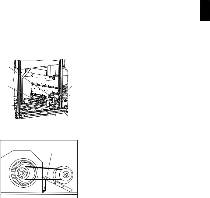
Condenser Fan Motor Protection
The condenser fan motor is internally protected against overtemperature.
Control Circuit, 24-V
The control circuit is protected against overcurrent conditions by a circuit breaker mounted on control transformer TRAN. Reset is manual.
GAS HEATING SYSTEM
General
The heat exchanger system consists of a gas valve feeding multiple inshot burners off a manifold. The burners fire into matching primary tubes. The primary tubes discharge into combustion plenum where gas flow converges into secondary tubes. The secondary tubes exit into the induced draft fan wheel inlet. The induced fan wheel discharges into a flue passage and flue gases exit out a flue hood on the side of the unit. The induced draft fan motor includes a Hall Effect sensor circuit that confirms adequate wheel speed via the Integrated Gas Control (IGC) board. Safety switches include a Rollout Switch (at the top of the burner compartment) and a limit switch (mounted through the fan deck, over the tubes). (See Fig. 29 and 30.)
INDUCED- |
|
|
DRAFT |
|
|
MOTOR |
ROLLOUT |
|
MOUNTING |
||
SWITCH |
||
PLATE |
||
|
||
BURNER |
FLUE |
|
SECTION |
EXHAUST |
|
INDUCED- |
VESTIBULE |
|
DRAFT MOTOR |
PLATE |
|
MANIFOLD |
|
|
PRESSURE |
|
|
TAP |
|
|
GAS |
BLOWER |
|
VALVE |
HOUSING |
|
|
C09153 |
Fig. 29 - Burner Section Details
Limit Switch |
and Shield |
C08284
Fig. 30 - Limit Switch Location
Fuel Types and Pressures
Natural Gas — The 48TC unit is factory-equipped for use with Natural Gas fuel at elevation under 2000 ft (610 m). See section Orifice Replacement for information in modifying this unit for installation at elevations above 2000 ft (610 m).
Gas line pressure entering the unit’s main gas valve must be within specified ranges. Adjust unit gas regulator valve as required or consult local gas utility.
Table 5 – Natural Gas Supply Line Pressure Ranges
UNIT MODEL |
UNIT SIZE |
MIN |
MAX |
|
|
|
|
|
|
48TC |
All |
4.0 in. wg |
13.0 in. wg |
|
(996 Pa) |
(3240 Pa) |
|||
|
|
|||
|
|
|
|
Manifold pressure is factory-adjusted for NG fuel use. Adjust as required to obtain best flame characteristic.
Table 6 – Natural Gas Manifold Pressure Ranges
UNIT |
UNIT |
HIGH |
LOW |
RANGE |
|
MODEL |
SIZE |
FIRE |
FIRE |
||
|
|||||
|
|
|
|
|
|
48TC |
All |
3.5 in. wg |
1.7 in. wg |
2.0---5.0 in. wg (Hi) |
|
(872 Pa) |
(423 Pa) |
(498---1245 Pa) |
|||
|
|
||||
|
|
|
|
|
Liquid Propane — Accessory packages are available for field-installation that will convert the 48TC unit to operate with Liquid Propane (LP) fuels. These kits include new orifice spuds, new springs for gas valves and a supply line low pressure switch. See section on Orifice Replacement for details on orifice size selections.
Fuel line pressure entering unit gas valve must remain within specified range.
Table 7 – Liquid Propane Supply Line Pressure Ranges
UNIT MODEL |
UNIT SIZE |
MIN |
MAX |
|
48TC |
All |
11.0 in. wg |
13.0 in. wg |
|
(2740 Pa) |
(3240 Pa) |
|||
|
|
|||
|
|
|
|
Manifold pressure for LP fuel use must be adjusted to specified range. Follow instructions in the accessory kit to make initial readjustment.
Table 8 – Liquid Propane Manifold Pressure Ranges
UNIT MODEL |
UNIT SIZE |
HIGH FIRE |
LOW FIRE |
|
48TC |
All |
10.0 in. wg |
5.0 in. wg |
|
(2490 Pa) |
(1245 Pa) |
|||
|
|
|||
|
|
|
|
Supply Pressure Switch — The LP conversion kit includes a supply low pressure switch. The switch contacts (from terminal C to terminal NO) will open the gas valve power whenever the supply line pressure drops below the setpoint. (See Fig. 31 and 32.) If the low pressure remains open for 15 minutes during a call for heat, the IGC circuit will initiate a Ignition Fault (5 flashes) lockout. Reset of the low pressure switch is automatic on rise in supply line pressure. Reset of the IGC requires a recycle of unit power after the low pressure switch has closed.
48TC
25
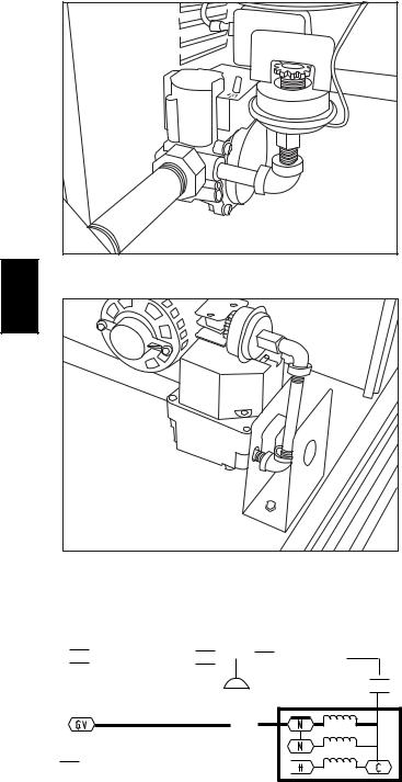
|
48TCDD08 only |
C08238 |
48TC |
|
|
|
|
|
|
|
C08239 |
All 48TC*D except DD08
Fig. 31 - LP Low Pressure Switch (Installed)
IGC |
LP LPS |
|


 BRN
BRN 
 C
C 

 NO
NO
 BRN J2-11
 C
C  MGV
MGV
IGC
GRA
J2-12
TSTAT
 W2
W2
 PNK
PNK 
C08285
Fig. 32 - LP Supply Line Low Pressure Switch Wiring
This switch also prevents operation when the propane tank level is low which can result in gas with a high concentration of impurities, additives, and residues that have settled to the bottom of the tank. Operation under these conditions can cause harm to the heat exchanger system. Contact your fuel supplier if this condition is suspected.
Flue Gas Passageways
To inspect the flue collector box and upper areas of the heat exchanger:
1.Remove the combustion blower wheel and motor assembly according to directions in Combustion-Air Blower section. (See Fig. 33.)
2.Remove the flue cover to inspect the heat exchanger.
3.Clean all surfaces as required using a wire brush.
Combustion-Air Blower
Clean periodically to assure proper airflow and heating efficiency. Inspect blower wheel every fall and periodically during heating season. For the first heating season, inspect blower wheel bi-monthly to determine proper cleaning frequency.
To access burner section, slide the sliding burner partition out of the unit.
To inspect blower wheel, shine a flashlight into draft hood opening. If cleaning is required, remove motor and wheel as follows:
1.Slide burner access panel out.
2.Remove the 7 screws that attach induced-draft motor housing to vestibule plate. (See Fig. 33.)
3.The blower wheel can be cleaned at this point. If additional cleaning is required, continue with Steps 4 and 5.
4.To remove blower from the motor shaft, remove 2 setscrews.
5.To remove motor, remove the 4 screws that hold the motor to mounting plate. Remove the motor cooling fan by removing one setscrew. Then remove nuts that hold motor to mounting plate.
6.To reinstall, reverse the procedure outlined above.
26
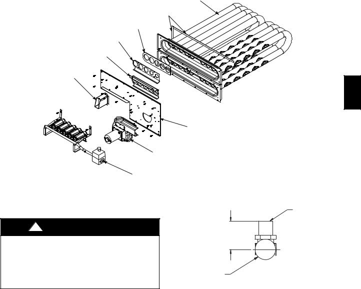
HEATER TUBE
ASSEMBLY
SEAL STRIPS,
SPONGE RUBBER
REGULATOR
GASKET
REGULATOR
RETAINER
WIND CAP ASSEMBLY (SHOWN INVERTED, AS SHIPPED)
SUPPORT INSULATION ASSEMBLY
INDUCER FAN-MOTOR ASSEMBLY
BURNER ASSEMBLY
C08227
Fig. 33 - Heat Exchanger Assembly
Burners and Igniters
!CAUTION
EQUIPMENT DAMAGE HAZARD
Failure to follow this caution may result in equipment damage.
When working on gas train, do not hit or plug orifice spuds.
ORIFICE
1.00-in
(25.4 mm)
MANIFOLD
PIPE
C08211
Main Burners
To access burners, remove burner access panel and slide out burner partition. At the beginning of each heating season, inspect for deterioration or blockage due to corrosion or other causes. Observe the main burner flames and adjust, if necessary.
Orifice projection — Refer to Fig. 34 for maximum projection dimension for orifice face to manifold tube.
Fig. 34 - Orifice Projection
Removal and Replacement of Gas Train
See Fig. 29, 33, and 35.
1.Shut off manual gas valve.
2.Shut off power to unit.
3.Slide out burner partition.
4.Disconnect gas piping at unit gas valve.
5.Remove wires connected to gas valve. Mark each wire.
48TC
27
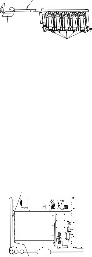
MANIFOLD PRESSURE TAP
GAS
VALVE
|
|
BURNERS |
|
|
C09154 |
|
|
Fig. 35 - Burner Tray Details |
|
6. |
Remove igniter wires and sensor wires at the Integ- |
|
|
rated Gas Unit Controller (IGC). (See Fig. 36.) |
|
|
|
48TC |
7. |
Remove the 2 screws that attach the burner rack to |
|
the vestibule plate. (See Fig. 33.) |
|
|
|
|
|
8. |
Slide the burner tray out of the unit. (See Fig. 35.) |
|
9. |
To reinstall, reverse the procedure outlined above. |
|
Cleaning and Adjustment
1.Remove burner rack from unit as described in Removal and Replacement of Gas Train section, above.
2.Inspect burners; if dirty, remove burners from rack. (Mark each burner to identify its position before removing from the rack.)
3.Use a soft brush to clean burners and cross-over port as required.
4.Adjust spark gap. (See Fig. 37.)
5.If factory orifice has been removed, check that each orifice is tight at its threads into the manifold pipe and that orifice projection does not exceed maximum valve. (See Fig. 34).
6.Reinstall burners on rack in the same locations as factory-installed. (The outside crossover flame regions of the outermost burners are pinched off to prevent excessive gas flow from the side of the burner assembly. If the pinched crossovers are installed between two burners, the flame will not ignite properly.)
RACEWAY |
|
INTEGRATED GAS UNIT |
|||||||||||||||||||||||||
|
CONTROLLER (IGC) |
||||||||||||||||||||||||||
|
|
|
|
|
|
|
|
|
|
|
|
|
|
|
|
|
|
|
|
|
|
|
|
|
|
|
|
|
|
|
|
|
|
|
|
|
|
|
|
|
|
|
|
|
|
|
|
|
|
|
|
|
|
|
|
|
|
|
|
|
|
|
|
|
|
|
|
|
|
|
|
|
|
|
|
|
|
|
|
|
|
|
|
|
|
|
|
|
|
|
|
|
|
|
|
|
|
|
|
|
|
|
|
|
|
|
|
|
|
|
|
|
|
|
|
|
|
|
|
|
|
|
|
|
|
|
|
|
|
|
|
|
|
|
|
|
|
|
|
|
|
|
|
|
|
|
|
|
|
|
|
|
|
|
|
|
|
|
|
|
|
|
|
|
|
|
|
|
|
|
|
|
|
|
|
|
|
|
|
|
|
|
|
|
|
|
|
|
|
|
|
|
|
|
|
|
|
|
|
|
|
|
|
|
|
|
|
|
|
|
|
|
|
|
|
|
|
|
|
|
|
|
|
|
|
|
|
|
|
|
|
|
|
|
|
|
|
|
|
|
|
|
|
|
|
|
|
|
|
|
|
|
|
|
|
|
|
|
|
|
|
|
|
|
|
|
|
|
|
|
|
|
|
|
|
|
|
|
|
|
|
|
|
|
|
|
|
|
|
|
|
|
|
|
|
|
|
|
|
|
|
|
|
|
|
|
|
|
|
|
|
|
|
|
|
|
|
|
|
|
|
|
|
|
|
|
|
|
|
|
|
|
|
|
|
|
|
|
|
|
|
|
|
|
|
|
|
|
|
|
|
|
|
|
|
|
|
|
|
|
|
|
|
|
|
|
|
|
|
|
|
|
|
|
|
|
|
|
|
|
|
|
|
|
|
|
|
|
|
|
|
|
|
|
|
|
|
|
|
|
|
|
|
|
|
|
|
|
|
|
|
|
|
|
|
|
|
|
|
|
|
|
|
|
|
|
|
|
|
|
|
|
|
|
|
|
|
|
|
|
|
|
|
|
|
|
|
|
|
|
|
|
|
|
|
|
|
|
|
|
|
|
|
|
|
|
|
|
|
|
|
|
|
|
|
|
|
|
|
|
|
|
|
|
|
|
|
|
|
|
|
|
|
|
|
|
|
|
|
|
|
|
|
HOLE IN END PANEL (HIDDEN)
C08454
Fig. 36 - Unit Control Box/IGC Location
7.Reinstall burner rack as described in Removal and Replacement of Gas Train section, above.
Gas Valve — All unit sizes are equipped with 2-stage gas valves. See Fig. 38 for locations of adjustment screws and features on the gas valves.
To adjust gas valve pressure settings:
IMPORTANT: Leak check all gas connections including the main service connection, gas valve, gas spuds, and manifold pipe plug. All leaks must be repaired before firing unit.
Check Unit Operation and Make Necessary Adjustments
NOTE: Gas supply pressure at gas valve inlet must be within specified ranges for fuel type and unit size. (See Table 5, 6, 7, and 8.)
1.Remove manifold pressure tap plug from manifold and connect pressure gauge or manometer. (See Fig. 35.)
2.Turn on electrical supply.
3.Turn on unit main gas valve.
4.Set room thermostat to call for heat. Verify highstage heat operation before attempting to adjust manifold pressure.
5.When main burners ignite, check all fittings, manifold, and orifices for leaks.
6.Adjust high-stage pressure to specified setting by turning the plastic adjustment screw clockwise to increase pressure, counter-clockwise to decrease pressure.
7.Set room thermostat to call for low-stage heat. Adjust low-stage pressure to specified setting.
8.Replace regulator cover screw(s) when finished.
9.With burner access panel removed, observe unit heating operation in both high stage and low stage operation. Observe burner flames to see if they are blue in appearance, and that the flames are approximately the same for each burner.
10.Turn off unit, remove pressure manometer and replace the 1/8 in. pipe fitting on the gas manifold. (See Fig. 35.)
Limit Switch
Remove blower access panel. Limit switch is located on the fan deck. (See Fig. 30.)
28
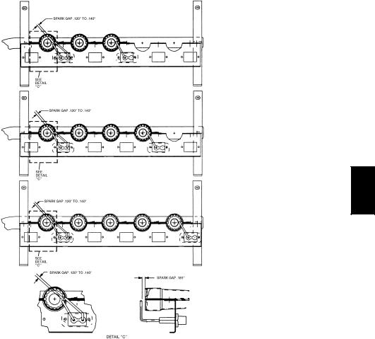
125,000/90,000 BTUH INPUT
180,000/120,000 BTUH INPUT
48TC
240,000/180,000 BTUH INPUT 250,000/200,000 BTUH INPUT
C08447
Fig. 37 - Spark Adjustment (08-14)
Burner Ignition
Unit is equipped with a direct spark ignition 100% lockout system. Integrated Gas Unit Controller (IGC) is located in the control box. (See Fig. 36.) The IGC contains a self-diagnostic LED (light-emitting diode). A single LED (see Fig. 39) on the IGC provides a visual display of operational or sequential problems when the power supply is uninterrupted. When a break in power occurs, the IGC will be reset (resulting in a loss of fault history) and the indoor (evaporator) fan ON/OFF times will be reset. The LED error code can be observed through the viewport. During servicing refer to the label on the control box cover or Table 9 for an explanation of LED error code descriptions.
If lockout occurs, unit may be reset by interrupting power supply to unit for at least 5 seconds.
Table 9 – LED Error Code Description*
LED INDICATION |
ERROR CODE |
|
DESCRIPTION |
||
|
||
|
|
|
ON |
Normal Operation |
|
|
|
|
OFF |
Hardware Failure |
|
|
|
|
2 Flashes |
Limit Switch Fault |
|
|
|
|
3 Flashes |
Flame Sense Fault |
|
|
|
|
4 Flashes |
4 Consecutive Limit Switch Faults |
|
|
|
|
5 Flashes |
Ignition Lockout Fault |
|
|
|
|
6 Flashes |
Induced---Draft Motor Fault |
|
|
|
|
7 Flashes |
Rollout Switch Fault |
|
|
|
|
8 Flashes |
Internal Control Fault |
|
|
|
|
9 Flashes |
Software Lockout |
|
|
|
LEGEND
LED --- Light Emitting Diode
*A 3 – second pause exists between LED error code flashes. If more than one error code exists, all applicable codes will be displayed in numerical sequence.
IMPORTANT: Refer to Troubleshooting Tables 13 and 14 for additional information.
29
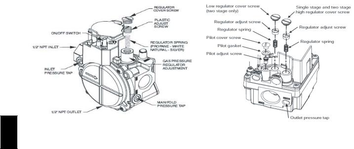
48TC
|
C08240 |
|
48TCDD08 only |
All 48TC*D except DD08 |
C08241 |
|
|
Fig. 38 - Gas Valve
Orifice Replacement
This unit uses orifice type LH32RFnnn (where nnn indicates orifice reference size). When replacing unit orifices, order the necessary parts via Carrier RCD. See Table 11 for available orifice sizes. See Table 12 for orifice sizes for Natural Gas and LP fuel usage at various elevations above sea level.
Check that each replacement orifice is tight at its threads into the manifold pipe and that orifice projection does not exceed maximum value. (See Fig. 34.)
30
 Loading...