


 Loading...
38VM/40VM Series VRF (Variable Refrigerant Flow) System Touch Screen Central Controller Accessory
Installation Instructions
Part Number 40VM900006
For Commercial Use Only
|
CONTENTS |
|
|
|
Page |
SAFETY CONSIDERATIONS....................................... |
1 |
|
GENERAL.................................................................. |
1 |
|
DIMENSIONAL DRAWINGS.......................................... |
2 |
|
INSTALLATION CONSIDERATIONS............................. |
4 |
|
INSTALLATION.......................................................... |
4 |
|
SETTING NETWORK ADDRESS....................................... |
6 |
|
BASIC CONFIGURATION.................................................... |
6 |
|
• |
LOGIN........................................................................ |
6 |
• |
BRAND CHOICE....................................................... |
7 |
• |
AUTO SEARCH......................................................... |
7 |
SAFETY CONSIDERATIONS
Read and follow manufacturer instructions carefully. Follow all local electrical codes during installation. All wiring must conform to local and national electrical codes. Improper wiring or installation may damage thermostat.
Understand the signal words — DANGER, WARNING, and CAUTION. DANGER identifies the most serious hazards which will result in severe personal injury or death. WARNING signifies hazards that could result in personal injury or death. CAUTION is used to identify unsafe practices, which would result in minor personal injury or product and property damage.
Recognize safety information. This
symbol ( ). When this symbol is displayed on the unit and in instructions or manuals, be alert to the potential for personal injury. Installing, starting up, and servicing equipment can be hazardous due to system pressure, electrical components, and equipment location.
GENERAL
The VRF (variable refrigerant flow) touch screen central controller is a wall-mounted, low-voltage controller that provides site-level control of multiple VRF systems. The controller allows central management of mode, setpoint, and scheduling of indoor units (IDUs).
The touch screen central controller is available for use with the VRF (variable refrigerant flow) outdoor units / systems listed in Table 1.
NOTES:
1.Changes or modifications of this product not expressly approved by the party responsible for compliance could void the user's authority to operate the equipment.
2.This equipment has been tested and found to comply with the limits for a Class A digital device, pursuant to Part 15 of the FCC Rules. These limits are designed to provide reasonable protection against harmful interference when the equipment is operated in a commercial environment. This equipment generates, uses, and can radiate radio
accordance with the instruction manual, may cause harmful interference to radio communications. Operation of this equipment in a residential area is likely to cause
harmful interference-in which case the user will be required to correct the interference at their own expense.
This equipment should be installed and operated with a minimum distance of 20 centimeters between the radiator
and your body.
Table 1: Touch Screen Central Controller
Accessory Usage
UNIT |
SIZES |
38VMAR Heat Recovery System 072,096,120,144, 168, 192, 216, 240, 264, 288, 312, 336
036, 048, 060, 072, 096, 120, 38VMAH Heat Pump System 144, 168, 192, 216, 240, 264, 288, 312, 336, 360, 384, 408,
432
Table 2: Components shipped with Unit
NAME |
IMAGE |
QTY |
|
FUNCTION |
|
Mounting |
|
|
1 |
Plastic mounting enclosure |
|
Box |
|
|
|||
|
|
|
|
|
|
Mounting |
|
|
|
Steel plate connecting |
|
|
|
1 controller to front of Mounting |
|||
Plate |
|
|
|||
|
|
|
|
Box |
|
|
|
|
|
|
|
Screws |
|
|
6 |
Used to Install Mounting Box |
|
(Short) |
|
|
|
to Wall |
|
|
|
|
|
||
Screws |
|
|
4 |
Used to install Mounting Plate |
|
|
|
on Mounting Box |
|||
|
|
|
|
||
|
|
|
|
Used to install Mounting Plate |
|
Washers |
|
|
8 |
on Mounting Box |
|
|
|
(2 extra washers for fine |
|||
|
|
|
|
||
|
|
|
|
adjustment if wall is uneven) |
|
|
|
Table 3: Specifications |
|||
Power Supply |
|
Rated Voltage |
24VAC, 60 Hz |
||
(field provided) |
Current Requirement |
1A |
|||
Dimensions |
|
|
H |
|
7-3/8 |
|
|
W |
|
10-7/8 |
|
(inches) |
|
|
|
||
|
|
D |
|
1-1/4 |
|
|
|
|
|
||
Total Weight |
|
Touch Screen Controller, Mounting Box, |
|||
|
Mounting Plate, & Screws: 2 lbs 12 oz |
||||
|
|
|
|||
Number of X/Y |
|
|
6 |
|
|
Bus Lines |
|
|
|
|
|
|
|
|
|
|
|
Max. Refrigerant |
|
8/64 |
|||
Systems/IDUs |
|
|
|||
per Line |
|
|
|
|
|
Manufacturer reserves the right to discontinue, or change at any time, specifications or designs without notice and without incurring obligations.
Catalog No. 17-40VM9006-01 |
Printed in China |
Form 40VM-5SIR1 |
Pg 1 |
09-17 |
Replaces: 40VM-5SI |
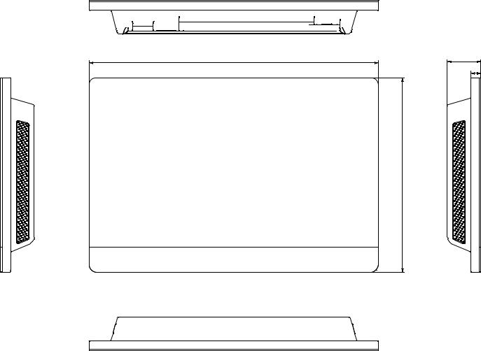
DIMENSIONAL DRAWING
10-7/8 |
1-1/4 |
3/8
7-3/8
Fig. 1 — Dimensions
2

R |
C |
X1 E Y1 · X2 E Y2 · X3 E Y3 |
X4 E Y4 · X5 E Y5 · X6 E Y6 |
DI1 · DI2 |
DO1 · DO2 |
AI1 · AI2 |
LAN |
USB |
||||
|
|
1 |
2 |
3 |
4 |
5 |
6 |
|
|
|
|
|
|
|
|
|
|
|
|
'2 Ɣ '2 |
|
LAN |
|
|
|
||
|
|
|
|
|
|
|
|
|
|
|
|
|
||
9$&,1 |
&20 a |
', Ɣ ', |
$, Ɣ$, |
|
|
USB |
||||||||
|
|
|
Fig. 2 — Connection Description |
|
|
|
|
|||||||
Table 4 — Connection Description |
|
|
|
|
|
|
|
|
|
|
||||
|
|
|
|
|
|
|
|
|
|
|
|
|
|
|
|
NAME |
|
|
|
|
|
|
|
|
FUNCTION |
||||
|
R |
|
|
24VAC power |
|
|
|
|
|
|
||||
|
C |
|
|
24VAC common |
|
|
|
|
|
|
||||
|
X |
|
|
X conductor, X/Y bus (no 1-6) |
|
|
|
|
||||||
|
Y |
|
|
Y conductor, X/Y bus (no 1-6) |
|
|
|
|
||||||
|
E |
|
|
Shield conductor, X/Y bus (no 1-6) |
||||||||||
|
DI1 |
|
|
Emergency Shutdown dry contact input* |
||||||||||
|
DI2 |
|
|
(reserved) |
|
|
|
|
|
|
||||
|
DO1 |
|
|
(reserved) |
|
|
|
|
|
|
||||
|
DO2 |
|
|
(reserved) |
|
|
|
|
|
|
||||
|
AI1 |
|
|
(reserved) |
|
|
|
|
|
|
||||
|
AI2 |
|
|
(reserved) |
|
|
|
|
|
|
||||
|
LAN |
|
|
Local Area Network connection, Ethernet |
||||||||||
|
USB |
|
|
Universal Serial Bus connection for service |
||||||||||
*Emergency Shutdown input is not suitable for life-safety applications, such as fire or smoke sequences.
3
Loading...