


48-50A020-060
Manufacturer reserves the right to discontinue, or change at any time, specifications or designs without notice and without incurring obligations.
PC 111 Catalog No. 534-80157 Printed in U.S.A. Form 48/50A-5SI Pg 1 9-03 Replaces: New
Book 1 1
Ta b 1 a 1 b
Installation Instructions
Part No. CRSMKDET002C00
CONTENTS
GENERAL
. . . . . . . . . . . . . . . . . . . . . . . . . . . . . . . . . . . . . . . . 1
SAFETY CONSIDERATIONS
. . . . . . . . . . . . . . . . . . . . . . 1
INSTALLATION
. . . . . . . . . . . . . . . . . . . . . . . . . . . . . . . . . 2-5
Check Package Contents
. . . . . . . . . . . . . . . . . . . . . . . . . 2
Return Air Smoke Detector Installation
. . . . . . . . . . . 2
48/50A Units
. . . . . . . . . . . . . . . . . . . . . . . . . . . . . . . . . . . . . . 2
48/50Z Units
. . . . . . . . . . . . . . . . . . . . . . . . . . . . . . . . . . . . . . 3
Configuring the
Comfort
Link™ Controller
. . . . . . . . 5
OPERATION
. . . . . . . . . . . . . . . . . . . . . . . . . . . . . . . . . . . . . . 5
MAINTENANCE
. . . . . . . . . . . . . . . . . . . . . . . . . . . . . . . . . . 5
Cleaning Procedure
. . . . . . . . . . . . . . . . . . . . . . . . . . . . . . 5
Filter Replacement
. . . . . . . . . . . . . . . . . . . . . . . . . . . . . . . 5
Board Replacement
. . . . . . . . . . . . . . . . . . . . . . . . . . . . . . 5
TROUBLESHOOTING
. . . . . . . . . . . . . . . . . . . . . . . . . . . .5,6
Smoke Entry Tests
. . . . . . . . . . . . . . . . . . . . . . . . . . . . . . . 5
• AIRFLOW TEST
• SMOKE RESPONSE TEST
Standby, Alarm and Sensitivity Tests
. . . . . . . . . . . . . 6
• STANDBY AND TROUBLE TEST
• ALARM TEST
• SENSITIVITY TEST
GENERAL
An HVAC (heating, ventilation and air-conditioning) sys-
tem supplies conditioned air to virtually every area of a
building. Smoke introduced into this air duct system will be
distributed throughout the entire building. Smoke detectors
designed for use inside the unit are used to sense the presence
of smoke passing through the unit.
The smoke detector utilizes photoelectric technology for the
detection of smoke. This detection method, when combined
with an efficient ducting design, samples air passing through
the unit. If sufficient smoke is sensed, an alarm signal is initiat-
ed and the ComfortLink controls will shut down the unit. With
the unit shut down, the unit will not blow toxic smoke and fire
gases throughout the areas served by the duct system.
SAFETY CONSIDERATIONS
Installation and servicing of air-conditioning equipment can
be hazardous due to system pressure and electrical compo-
nents. Only trained and qualified service personnel should
install, repair, or service air-conditioning equipment.
Untrained personnel can perform the basic maintenance
functions of cleaning coils and filters and replacing filters. All
other operations should be performed by trained service per-
sonnel. When working on air-conditioning equipment, observe
precautions in the literature, tags and labels attached to the unit,
and other safety precautions that may apply.
Follow all safety codes. Wear safety glasses and work
gloves. Use care when handling and installing the accessory.
Before performing service or maintenance operations on
unit, turn off main power swit ch to unit. Electrical shock
could cause personal injury.
The National Fire Protection Association has established
that DUCT DETECTORS MUST NOT BE USED AS A
SUBSTITUTE FOR OPEN AREA DETECTOR PRO-
TECTION as a means of providing life safety. Nor are they
a substitute for early warning in a building’s regular fire
detection system. Carrier supports this positi on and strongly
recommends that the user read NFPA Standards 90A, 72,
and 101. This smoke detector is listed per UL 2 68A.
This device will not operate without electrical power.
Fire situations may cause an interruption of power. The
system safeguards should be discussed with your local fire
protection specialist.
This device will not sense smoke unless the ventilation sys-
tem is operating and the cover is installed.
For this detector to function properly, it MUST be installed
according to the instructions in this manual. Furthermore,
the detector MUST be operated within ALL e lectrical and
environmental specifications listed in this manual. Failure
to comply with these requirements may prevent the detec-
tor from activating when smoke is present in the air duct.
48/50A020-060
48/50Z030-105
Single-Package Rooftop Units
Accessory Return Smoke Detectors
2
INSTALLATION
Check Package Contents —
Remove accessory pack-
aging and inspect shipment for damage. If any damage is
found, file a claim with the shipping agent immediately. If any
item is missing or any part does not assemble properly, notify
your Carrier distributor.
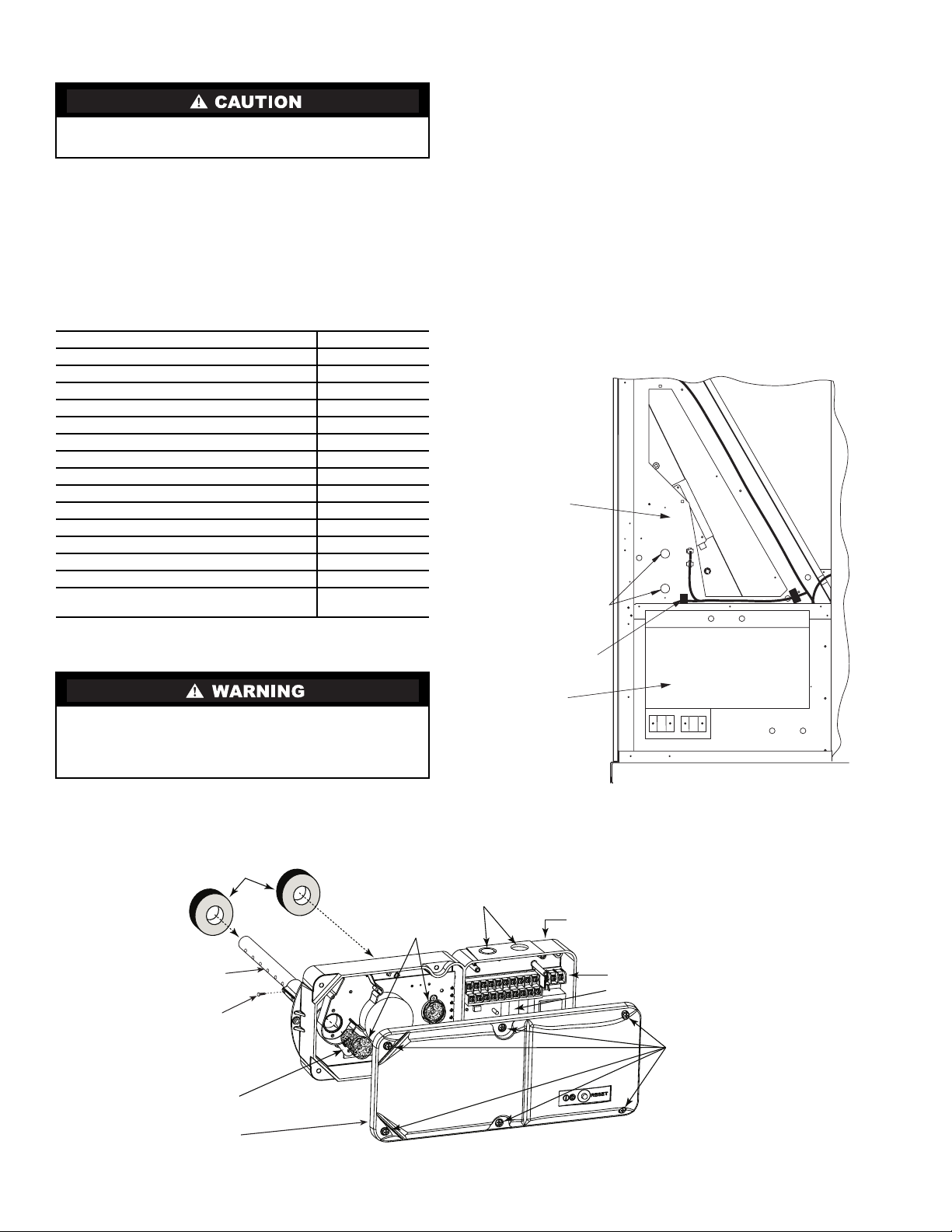
T able 1 lists the accessory package contents. Figure 1 shows
the smoke detector.
Table 1 — Accessory Package Contents — Return
Air Smoke Detector (CRSMKDET002C00)
Return Air Smoke Detector Installation
NOTE: For horizontal applications it is easiest to install the
smoke detector prior to making duct connections.
48/50A Units —
The return air smoke detector is to be
installed in the predrilled holes located in the indoor section
above the auxiliary control box.
1. Open the hinged auxiliary control box access door and
secure.
2. Find the 2 plugs located in the partition above the control
box, remove and discard. See Fig. 2.
3. Remove cover from smoke detector. The screws will
remain captured in the cover.
4. Place foam gaskets over each sampling tube on smoke
detector. See Fig. 1.
5. Remove one knockout from top of smoke detector.
6. Insert stripped ends of wire harness through knockout and
wire to smoke detector as shown in Fig. 3. Use ground
screw in the smoke detector to secure a wire tie. Use wire
tie to provide strain relief for the wire harness.
7. Slide smoke detector into holes in partition. Do not secure
at this time.
When installing the smoke detector in the unit, follow all
local codes. Damage to unit may result.
ITEM QUANTITY
Smoke Detector with Cover
1
Sampling Tube (long)
1
Sampling Tube Filters
2
Test Magnet
1
Foam Gaskets
2
Screw, no. 6 Self Tapping
2
Tube End Plug (large)
1
Sampling Tube Support Bracket
1
Screw, 8-18
3
/
4
-in. Pan Head
2
Screw,
1
/
4
AB-14
5
/
8
-in.
2
Snap Bushing
1
Harness Assembly
1
Smoke detector bracket 50ZZ500420
1
Sampling tube bracket 50ZZ500421
1
Sampling tube bracket 50ZZ500431
(48/50Z030-050 with Power Exhaust)
1
Prior to instal lation of this access ory, make sure all power
is disconnected to the unit and locked out. Failure to dis-
connect power supply prior to servicing may result in seri-
ous injury.
FOAM
GASKETS
CONDUIT HOLES
DETECTOR
HOUSING
TERMINAL STRIP
POWER BOARD
COVER MOUNTING
SCREWS
FILTERS
SAMPLING TUBE
DETECTOR BOARD
DETECTOR COVER
PLASTIC
SAMPLING TUBE
PLASTIC SAMPLING TUBE
SELF-TAPPING SCREW
PHOTO
Fig. 1 — Smoke Detector
SMOKE DETECTOR
MOUNTING PLUGS
PARTITION
PL13
AUXILIARY
CONTROL PANEL
Fig. 2 — Smoke Detector Mounting Location for
48/50A020-060
3
8. Insert tube end plug into sampling tube and slide sam-
pling tube into bottom hole of smoke detector.
9. Remove the unit side panel at the return end of the unit
(downshot units only). Save screws for use later.
10. Mount the sampling tube support bracket to the cross
member with two
1
/
4
AB-14
5
/
8
-in. screws as shown in
Fig. 4. Insert snap bushing into hole in bracket.
11. Slide sampling tube into bracket, making sure that the
sampling holes point in the opposite direction of the re-
turn air flow. Insert the sampling tube all the way into the
smoke detector.
12. Return to the auxiliary control box and secure sampling
tube to smoke detector with two no. 6 self-tapping
screws.
13. Attach smoke detector to partition using two, 8-18
3
/
4
-in.
pan head screws. See Fig. 4.
14. Return to side panel and insert tube end plug into
sampling tube.
15. Replace the unit side panel.
16. Return to auxiliary control box section and insert sam-
pling tube filters into both sampling tube holders. (See
Fig. 1.)
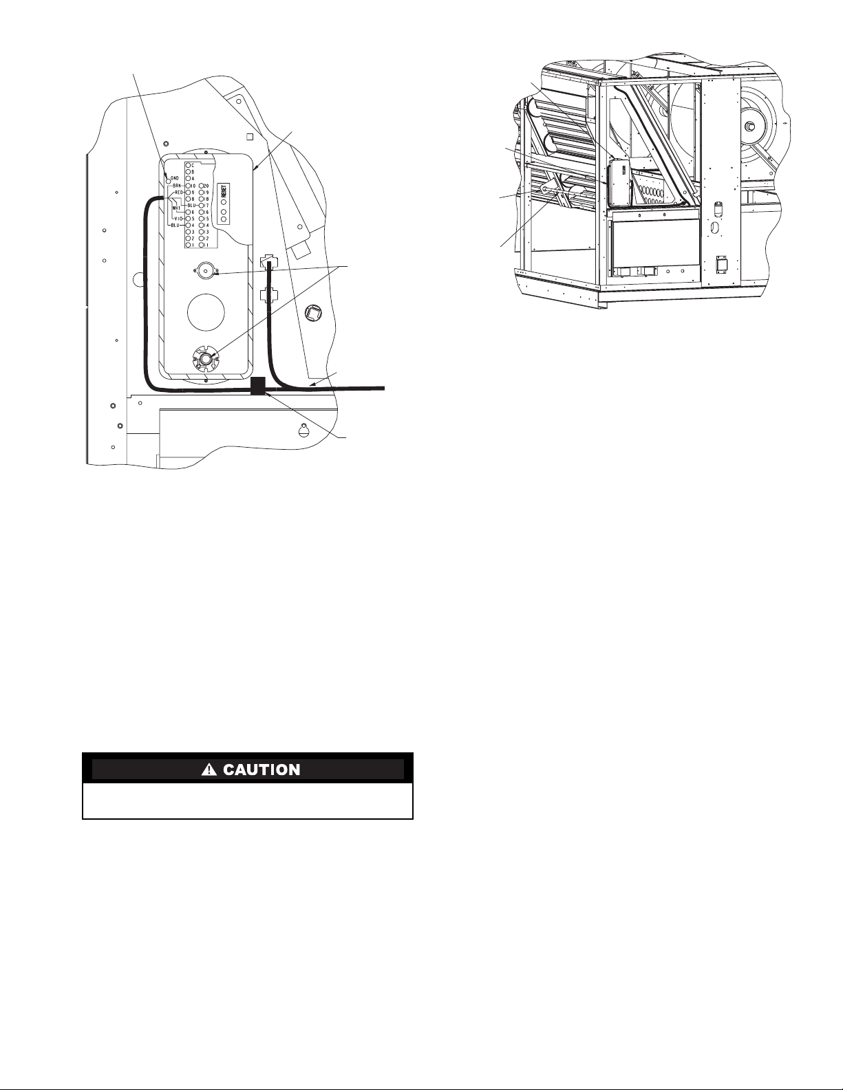
17. Connect harness PL13 as shown in Fig. 3.
18. Restore power to the unit.
19. Configure ComfortLink™ controller as specified in
Controls and Troubleshooting Guide.
20. Perform Standby , Alarm, and Sensitivity Tests on page 6.
At a minimum, the Magnet test should be performed t o
verify smoke detector wiring.
21. Replace smoke detector cover.
22. Check for alarms. Correct any problems.
23. Close and secure auxiliary control box door.
48/50Z Units —
The return air smoke detector is to be
installed on the upright in the power exhaust section. See
Fig. 5-10.
NOTE: For size 075-105 units with return fan option, the
smoke detector should be installed in the return duct. Do not
use the bracket provided in this accessory kit.
1. Open the power exhaust section doors/panels on both
sides of the unit to gain access.
2. Find plug 13 in the power exhaust section.
3. Remove cover from smoke detector. The screws will re-
main captured in the cover.
4. Place foam gaskets over each sampling tube on smoke
detector. See Fig. 1.
5. Remove one knockout from top of smoke detector.
6. Insert stripped ends of wire harness through knockout and
wire to smoke detector as shown in Fig. 3. Use ground
screw in the smoke detector to secure a wire tie. Use wire
tie to provide strain relief for the wire harness.
7. Mount the smoke detector bracket 50ZZ500420 on the
upright.
See Fig. 5 for size 030-050 units without economizer.
See Fig. 6 for size 030-050 units with economizer only
option.
See Fig. 7 for size 030-050 units with economizer and
power exhaust option.
See Fig. 8 for size 055-105 units without economizer.
See Fig. 9 for size 055-105 units with economizer only
option.
See Fig. 10 for size 055-105 units with economizer and
power exhaust option.
8. Slide smoke detector into holes in bracket. Do not secure
at this time.
9. Insert tube end plug into sampling tube and slide
sampling tube into bottom hole of smoke detector.
10. Mount the sampling tube bracket to the bottom of the
power exhaust section using two
1
/
4
AB-14-
5
/
8
-in. screws.
For size 030-050 units with power exhaust, use bracket
50ZZ500431 as shown on Fig. 7. For all other units
use bracket 50ZZ500421, as shown on Fig. 5 and 6 for
size 030-050 units, Fig. 8-10 for size 055-105 units.
Do not overtighten the screws. Damage to smoke detector
may result.
GROUND
SCREW
SMOKE
DETECTOR
PL13
SAMPLING
TUBE
FILTERS
WIRE HARNESS
Fig. 3 — Smoke Detector Wiring Connections
SMOKE
DETECTOR
WIRE
HARNESS
SAMPLING
TUBE
SUPPORT
BRACKET
SAMPLING
TUBE
Fig. 4 — Smoke Detector Installed (48/50A020-060)
 Loading...