


48TC-16

48TC**16
Single Package Rooftop
Gas Heating/Electric Cooling Unit
with Puronr (R---410A) Refrigerant
Size 16
Installation Instructions
NOTE: Read the entire instruction manual before starting
the installation
TABLE OF CONTENTS
SAFETY CONSIDERATIONS 2....................
INSTALLATION 4...............................
Jobsite Survey 4................................
Step 1 -- Plan for Unit Location 4..................
Roof Mount 5...............................
Step 2 -- Plan for Sequence of Unit Installation 5......
Curb--Mount Installation 5.....................
Pad--Mount Installation 5......................
Frame--Mount Installation 5....................
Step 3 -- Inspect Unit 5...........................
Step 4 -- Provide Unit Support 5...................
Roof Curb Mount 5..........................
Slab Mount (Horizontal Units Only) 5...........
Alternate Unit Support
(In Lieu of Curb or Slab Mount) 5..............
Step 5 -- Field Fabricate Ductwork 7................
Step 6 -- Rig and Place Unit 7.....................
Positioning on Curb 8........................
Step 7 -- Convert to Horizontal and Connect Ductwork 8...
Step 8 -- Install Outside Air Hood 9................
Economizer Hood Removal and Setup —
Factory Option 9............................
Two Position Damper Hood Removal and Setup —
Factory Option 9............................
Economizer Hood and Two--Position Hood 10.....
Step 9 -- Install Flue Hood 10.....................
Step 10 -- Install Gas Piping 11....................
Factory--Option Thru--Base Connections
(Gas Connections) 11.........................
Step 11 -- Install External Condensate Trap and Line 13..
Step 12 -- Make Electrical Connections 14...........
Field Power Supply 14........................
All Units 15................................
Units without Factory--Installed Disconnect 15....
Units with Factory--Installed Disconnect 15.......
Convenience Outlets 16.......................
Factory--Option Thru--Base Connections
(Electrical Connections) 18....................
Units without Thru--Base Connections 18.........
Field Control Wiring 18.......................
Thermostat 18...............................
Unit without Thru--Base Connection Kit 19.......
Heat Anticipator Settings 19...................
Humidi--MiZer
Humidi--MiZer -- Space RH Controller 20........
PremierLinkt (Factory Option) 21.................
Supply Air Temperature (SAT) Sensor 25.........
Outdoor Air Temperature (OAT) Sensor 25.......
EconoMi$er2 25.............................
Field Connections 25..........................
Space Sensors 27............................
Connect Thermostat 27.......................
Configure the Unit for Thermostat Mode 27......
Economizer Controls 28........................
Indoor Air Quality (CO
Outdoor Air Quality Sensor 28.................
Space Relative Humidity Sensor or
Humidistat Connections 29....................
Smoke Detector/Fire Shutdown (FSD) 30.........
Filter Status Switch 30........................
Supply Fan Status Switch 30...................
Remote Occupied Switch 30...................
Power Exhaust (output) 30.....................
CCN Communication Bus 31..................
RTU Open Control System 32.....................
Supply Air Temperature (SAT) Sensor 35.........
Outdoor Air Temperature (OAT) Sensor 35.......
EconoMi$er2 35.............................
Field Connections 35..........................
Space Temperature (SPT) Sensors 36............
Indoor Air Quality (CO
R
Control Connections 20..........
sensor) 28.............
2
)Sensor 36.............
2
Outdoor Air Quality Sensor 37.................
Space Relative Humidity Senor or Humidistat 37..
Smoke Detector/Fire Shutdown (FSD) 38.........
Connecting Discrete Inputs 38..................
Communication Wiring -- Protocols 39............
General 39.................................
Local Access 40.............................
RTU Open Troubleshooting 40.................
Outdoor Air Enthalpy Control 41.................
Differential Enthalpy Control 41................
Return Air Enthalpy Sensor 41.................
Smoke Detectors 42.............................
System 42..................................
Controller 42...............................
Sensor Module 42...........................
48TC**16
Smoke Detector Locations 43....................
Supply Air 43...............................
Return Air without Economizer 43..............
Return Air with Economizer 43.................
Step 13 -- Adjust Factory--Installed Options 46........
Step 14 -- Install Accessories 46...................
!
WARNING
FIRE, EXPLOSION HAZARD
Failure to follow this warning could result in personal
injury or death.
Disconnect gas piping from unit when leak testing at
pressure greater than 0.5 psig (3450 Pa). Pressures
greater than 0.5 psig (3450 Pa) will cause gas valve
damage resulting in hazardous condition. If gas valve
is subjected to pressure greater than 0.5 psig (3450
Pa), it must be replaced before use. When pressure
testing field--supplied gas piping at pressures of 0.5
psig (3450 Pa) or less, a unit connected to such piping
must be isolated by closing the manual gas valve.
!
WARNING
ELECTRICAL SHOCK HAZARD
Failure to follow this warning could cause personal
injury or death.
Before performing service or maintenance operations
on unit, always turn off main power switch to unit and
install lock(s) and lockout tag(s). Unit may have more
than one power switch.
SAFETY CONSIDERATIONS
Improper installation, adjustment, alteration, service,
maintenance, or use can cause explosion, fire, electrical
shock or other conditions which may cause personal injury
or property damage. Consult a qualified installer, service
agency, or your distributor or branch for information or
assistance. The qualified installer or agency must use
factory--authorized kits or accessories when modifying this
product. Refer to the individual instructions packaged with
the kits or accessories when installing.
Follow all safety codes. Wear safety glasses and work gloves.
Use quenching cloths for brazing operations and have a fire
extinguisher available. Read these instructions thoroughly and
follow all warnings or cautions attached to the unit. Consult
local building codes and appropriate national electrical codes
(in USA, ANSI/NFPA70, National Electrical Code (NEC); in
Canada, CSA C22.1) for special requirements.
It is important to recognize safety information. This is the
safety--alert symbol
unit and in instructions or manuals, be alert to the
potential for personal injury.
Understand the signal words DANGER, WARNING,
CAUTION, and NOTE. These words are used with the
safety--alert symbol. DANGER identifies the most serious
hazards which will result in severe personal injury or
death. WARNING signifies hazards which could result in
personal injury or death. CAUTION is used to identify
unsafe practices, which may result in minor personal
injury or product and property damage. NOTE is used to
highlight suggestions which will result in enhanced
installation, reliability, or operation.
. When you see this symbol on the
!
WARNING
UNIT OPERATION AND SAFETY HAZARD
Failure to follow this warning could cause personal
injury, death and/or equipment damage.
Puronr (R--410A) refrigerant systems operate at
higher pressures than standard R--22 systems. Do not
use R--22 service equipment or components on Puron
refrigerant equipment.
!
WARNING
PERSONAL INJURY AND ENVIRONMENTAL
HAZARD
Failure to follow this warning could cause personal
injury or death.
Relieve pressure and recover all refrigerant before
system repair or final unit disposal.
Wear safety glasses and gloves when handling
refrigerants. Keep torches and other ignition sources
away from refrigerants and oils.
!
CAUTION
CUT HAZARD
Failure to follow this caution may result in personal
injury.
Sheet metal parts may have sharp edges or burrs. Use
care and wear appropriate protective clothing, safety
glasses and gloves when handling parts and servicing
air conditioning equipment.
2
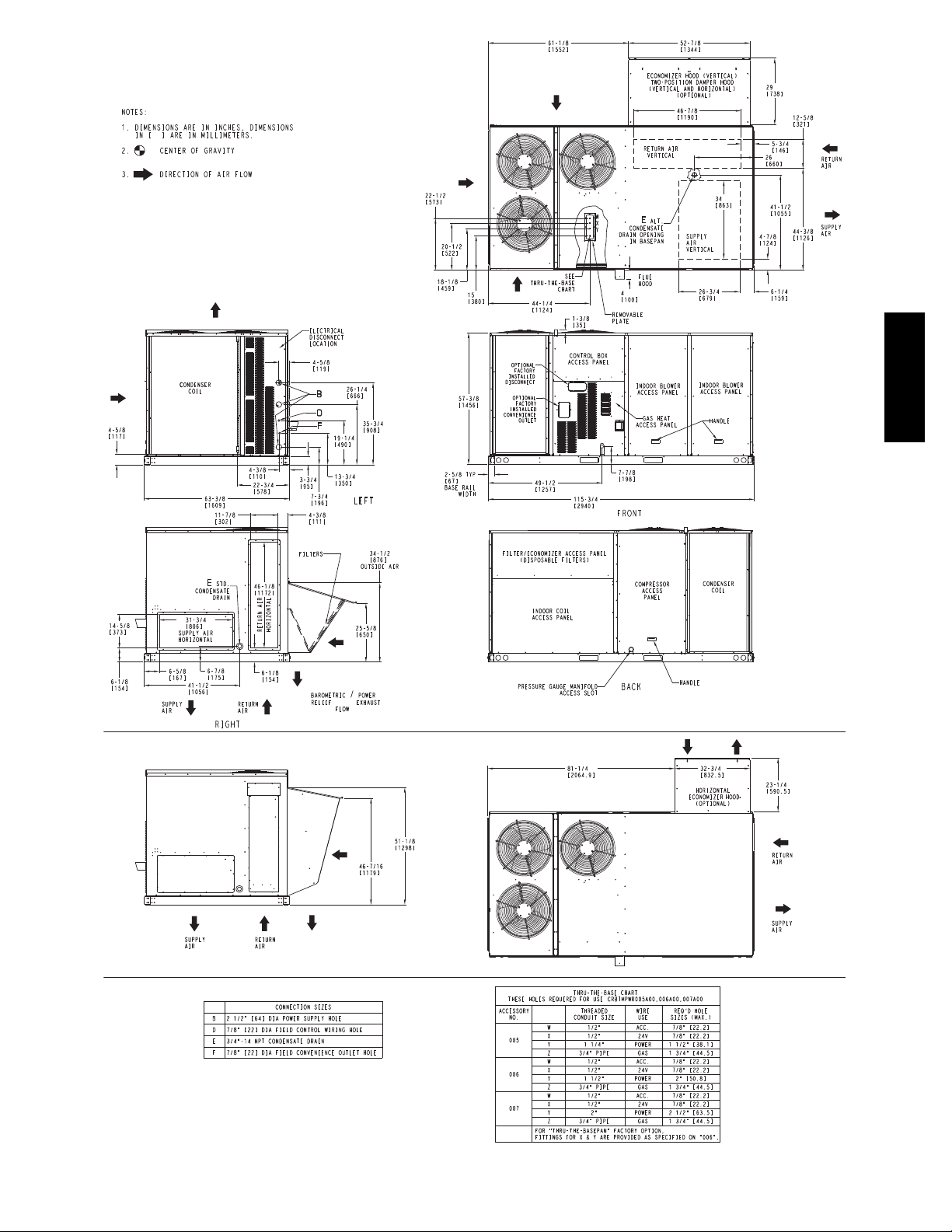
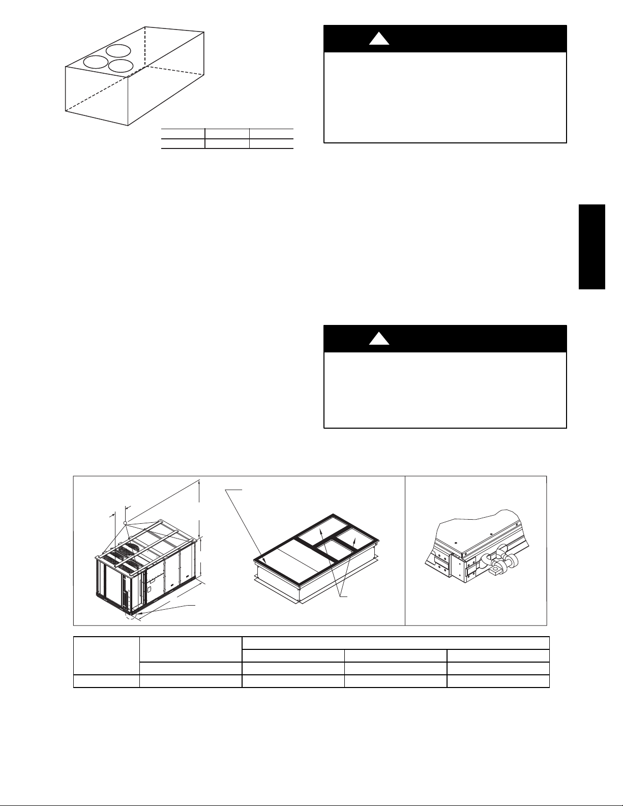
Vertical Connections / Economizer
48TC**16
Horizontal Connections / Economizer
Fig. 1 -- Unit Dimensional Drawing – 16 Size Unit
3
C10864A

48TC**16
Fig. 1 -- Unit Dimensional Drawing – 16 Size Unit (cont.)
INSTALLATION
Jobsite Survey
Complete the following checks before installation.
1. Consult local building codes and the NEC (National
Electrical Code) ANSI/NFPA 70 for special installation requirements.
2. Determine unit location (from project plans) or select
unit location.
3. Check for possible overhead obstructions which may
interfere with unit lifting or rigging.
Step 1 — Plan for Unit Location
Select a location for the unit and its support system (curb
or other) that provides for at least the minimum clearances
required for safety. This includes the clearance to
combustible surfaces, unit performance and service access
below, around and above unit as specified in unit
drawings. See Fig. 2.
NOTE: Consider also the effect of adjacent units.
Unit may be installed directly on wood flooring or on Class
A, B, or C roof--covering material when roof curb is used
Do not install unit in an indoor location. Do not locate air
inlets near exhaust vents, relief valves, or other sources of
contaminated air.
C10862A
18”
(457)
*
42"
(1067)
Required bottom condensate drain connection.
*
Otherwise, 36” (914mm) for condensate connection.
42"
(1067)
42"
(1067)
C09897
Fig. 2 -- Service Clearance Dimensional Drawing
Although unit is weatherproof, avoid locations that permit
water from higher level runoff and overhangs to fall onto
the unit.
Select a unit mounting system that provides adequate
height to allow for removal and disposal of frost and ice
that will form during the heating--defrost mode as well as
allow installation of condensate trap per requirements.
Refer to Step 11 — Install External Condensate Trap and
Line – for required trap dimensions.
4
Roof Mount —
Check building codes for weight distribution
requirements. Unit operating weight is shown in Table 1.
Step 3 — Inspect Unit
Inspect unit for transportation damage. File any claim
with transportation agency.
Table 1 – Operating Weights
48TC**16
COMPONENT UNITS LB (KG)
Base Unit 1380 (627)
Economizer
Vertical 100 (45)
Horizontal 115 (52)
H u m i di --- M i Ze rRSystem 62 (28)
Powered Outlet 32 (15)
Curb
14--- in/356 mm 180 (82)
24--- in/610 mm 235 (107)
Step 2 — Plan for Sequence of Unit Installation
The support method used for this unit will dictate different
sequences for the steps of unit installation. For example,
on curb--mounted units, some accessories must be
installed on the unit before the unit is placed on the curb.
Review the following for recommended sequences for
installation steps.
Curb--mounted installation —
Install curb, making sure to position the common cross
rail (see Fig. 3) for large duct opening.
Install field--fabricated ductwork inside curb
Complete installation of the factory--installed
thru--the--base service connection option
Prepare bottom condensate drain connection to suit
planned condensate line routing (refer to Step 9 for
details)
Rig and place unit
Install outdoor air hood
Install condensate line trap and piping
Make electrical connections
Install other accessories
Pad--mounted installation —
Prepare pad and unit supports
Check and tighten the bottom condensate drain
connection plug
Rig and place unit
Convert unit to side duct connection arrangement
Install field--fabricated ductwork at unit duct openings
Install outdoor air hood
Install condensate line trap and piping
Make electrical connections
Install other accessories
Frame--mounted installation —
Frame--mounted applications generally follow the
sequence for a curb installation. Adapt as required to
suit specific installation plan.
Confirm before installation of unit that voltage, amperage
and circuit protection requirements listed on unit data
plate agree with power supply provided.
Step 4 — Provide Unit Support
Roof Curb Mount —
Accessory roof curb details and dimensions are shown in
Fig. 3. Assemble and install accessory roof curb in
accordance with instructions shipped with the curb.
NOTE: The gasketing of the unit to the roof curb is
critical for a watertight seal. Install gasket supplied with
the roof curb as shown in Fig. 3. Improperly applied
gasket can also result in air leaks and poor unit
performance.
Curb should be level. This is necessary for unit drain to
function properly. Unit leveling tolerances are show in
Fig. 4. Refer to Accessory Roof Curb Installation
Instructions for additional information as required.
Install insulation, cant strips, roofing felt, and counter
flashing as shown. Ductwork must be attached to curb and
not to the unit.
IMPORTANT:
If the unit’s gas connection and/or electric and control
wiring is to be routed through the basepan and the unit
is equipped with the factory--installed Thru--the--Base
service option see the following sections:
S Factory--Option Thru--Base Connections
(Gas Connection) on page 11
S Factory--Option Thru--Base Connections
(Electrical Connections) on page 17
If using the field--installed Thru--the--Base accessory
follow the instructions provided with the accessory kit.
NOTE: If gas and/or electrical connections are not
going to occur at this time, tape or otherwise cover the
fittings so that moisture does not get into the building or
conduit in the interim.
Slab Mount (Horizontal Units Only) —
Provide a level concrete slab that extends a minimum of
6 in. (150 mm) beyond unit cabinet. Install a gravel apron
in front of condenser coil air inlet to prevent grass and
foliage from obstructing airflow.
NOTE: Horizontal units may be installed on a roof curb
if required.
Alternate Unit Support
(InLieuofCurborSlabMount)—
A non--combustible sleeper rail can be used in the unit curb
support area. If sleeper rails cannot be used, support the long
sides of the unit with a minimum of 3 equally spaced 4--in. x
4--in. (102 mm x 102 mm) pads on each side.
48TC**16
5
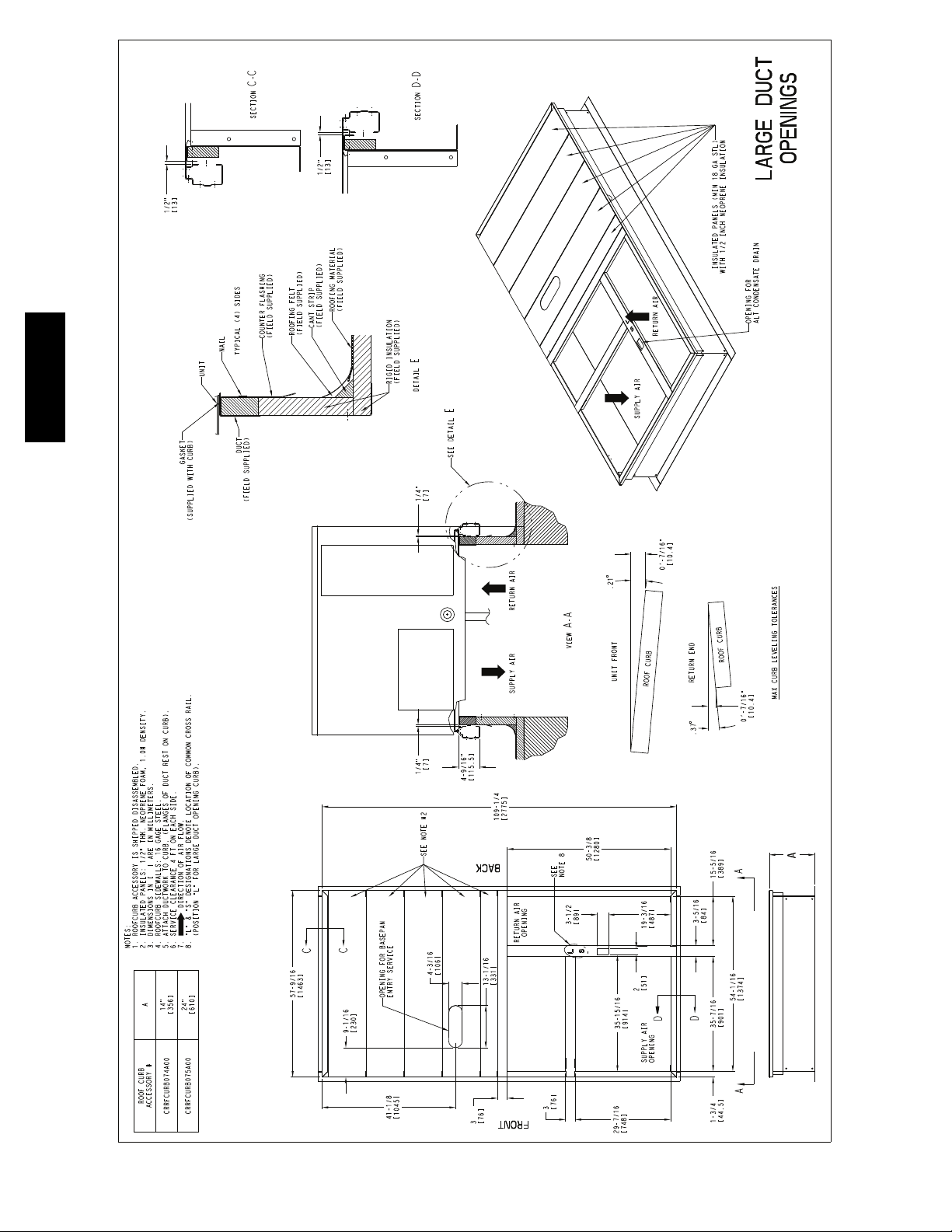
48TC**16
Fig. 3 -- Roof Curb Details
6
C10772
!
CAUTION
C
A
B
MAXIMUM ALLOWABLE
DIFFERENCE IN. (MM)
A-B
0.5” (13)
B-C
1.0” (25)
A-C
1.0” (25)
C10001
Fig. 4 -- Unit Leveling Tolerances
Step 5 — Field Fabricate Ductwork
NOTE: Cabinet return-air static pressure (a negative
condition) shall not exceed 0.35 in. wg (87 Pa) with
economizer or 0.45 in. wg (112 Pa) without economizer.
For vertical ducted applications, secure all ducts to roof curb
and building structure. Do not connect ductwork to unit.
Fabricate supply ductwork so that the cross sectional
dimensions are equal to or greater than the unit supply
duct opening dimensions for the first 18 in. (458 mm) of
duct length from the unit basepan.
Insulate and weatherproof all external ductwork, joints,
and roof openings with counter flashing and mastic in
accordance with applicable codes.
Ducts passing through unconditioned spaces must be
insulated and covered with a vapor barrier.
If a plenum return is used on a vertical unit, the return
should be ducted through the roof deck to comply with
applicable fire codes.
PROPERTY DAMAGE HAZARD
Failure to follow this caution may result in damage
to roofing materials.
Membrane roofs can be cut by sharp sheet metal
edges. Be careful when placing any sheet metal parts
on such roof.
Step 6 — Rig and Place Unit
When the unit is ready to be rigged and no longer will be
lifted by a fork truck, the wood protector under the basepan
must be removed. Remove 4 screws from each base rail.
Wood protector will drop to the ground. See instructions on
the unit base rails.
Keep unit upright and do not drop. Spreader bars are
required. Rollers may be used to move unit across a roof.
Level by using unit frame as a reference. See Table 1 and
Fig. 5 for additional information.
Lifting holes are provided in base rails as shown in Fig. 5.
Refer to rigging instructions on unit.
!
UNIT DAMAGE HAZARD
Failure to follow this caution may result in
equipment damage.
All panels must be in place when rigging. Unit is not
designed for handling by fork truck.
Before setting the unit onto the curb, recheck gasketing on
curb.
CAUTION
48TC**16
PLACE ALL SEAL STRIP IN PLACE BEFORE PLACING
UNIT ON ROOF CURB.
“B”
UNIT
48TC**16 2130 968 116.0 2945 60.5 1535 59.5 1510
NOTES:
1. SPREADER BARS REQUIRED — Top damage will occur if spreader bars are not used.
2. Dimensions in ( ) are in millimeters.
3. Hook rigging shackles through holes in base rail, as shown in detail “A.” Holes in base rails are centered around
the unit center of gravity . U se wooden top to prevent rigging straps from damaging unit .
914 - 1371
( 36” - 54” )
“C”
“A”
SEE DETAIL “A”
MAX WEIGHT
LB KG IN MM IN MM IN MM
A B C
DUCT END
DIMENSIONS
DETAIL “A”
Fig. 5 -- Rigging Details
7
C10774

PositioningonCurb—
For full perimeter curbs CRRFCURB074A00 and 075A00,
the clearance between the roof curb and the front and rear
1
base rails should be
the curb and the end base rails should be
/4in (6.4 mm). The clearance between
1
/2in (13 mm). For
retrofit applications with curbs CRRFCURB003A01 and
4A01, the unit should be position as shown in Fig. 6.
5
Maintain the 15.5 in (394 mm) and 8
5
clearances and allow the 22
/16in (567 mm) dimension to
/8in (220 mm)
float if necessary.
Fig. 6 -- Retrofit Installation Dimensions
48TC**16
If the alternative condensate drain location through the
bottom of the unit is used in conjunction with a retrofit
curb, the hole in the curb must be moved 12.5 in (320
mm) towards the duct end of the unit. (See Fig. 7.)
Original
Position
New Position
(moved 12.5 in.)
C10003
Remove all shipping materials and top skid. Remove extra
center post from the condenser end of the unit so that the
condenser end of the unit matches Figs. 26 and 27.
Recycle or dispose of all shipping materials.
Step 7 — Convert to Horizontal and Connect
Ductwork (when required)
Unit is shipped in the vertical duct configuration. Unit
without factory--installed economizer or return air smoke
detector option may be field--converted to horizontal ducted
configuration using accessory CRDUCTCV001A00. To
convert to horizontal configuration, remove screws from side
duct opening covers and remove covers.
Discard the supply duct cover. Install accessory
CRDUCTCV001A00 to cover the vertical supply duct
opening. Use the return duct cover removed from the end
panel to cover the vertical return duct opening.
Field--supplied flanges should be attached to horizontal
duct openings and all ductwork should be secured to the
flanges. Insulate and weatherproof all external ductwork,
joints, and roof or building openings with counter flashing
and mastic in accordance with applicable codes.
Do not cover or obscure visibility to the unit’s informative
data plate when insulating horizontal ductwork.
C10904
Fig. 7 -- Alternative Condensate Drain Hole Positions
Although unit is weatherproof, guard against water from
higher level runoff and overhangs.
IMPORTANT:
If the unit has the factory--installed Thru--the--Base
option, make sure to complete installation of the option
before placing the unit on the roof curb.
See the following sections:
S Factory--Option Thru--Base Connections
(Gas Connection) on page 11
S Factory--Option Thru--Base Connections
(Electrical Connections) on page 17
NOTE: If gas and/or electrical connections are not
going to occur at this time, tape or otherwise cover the
fittings so that moisture does not get into the building or
conduit in the interim.
C06108
Fig. 8 -- Horizontal Conversion Panels
8
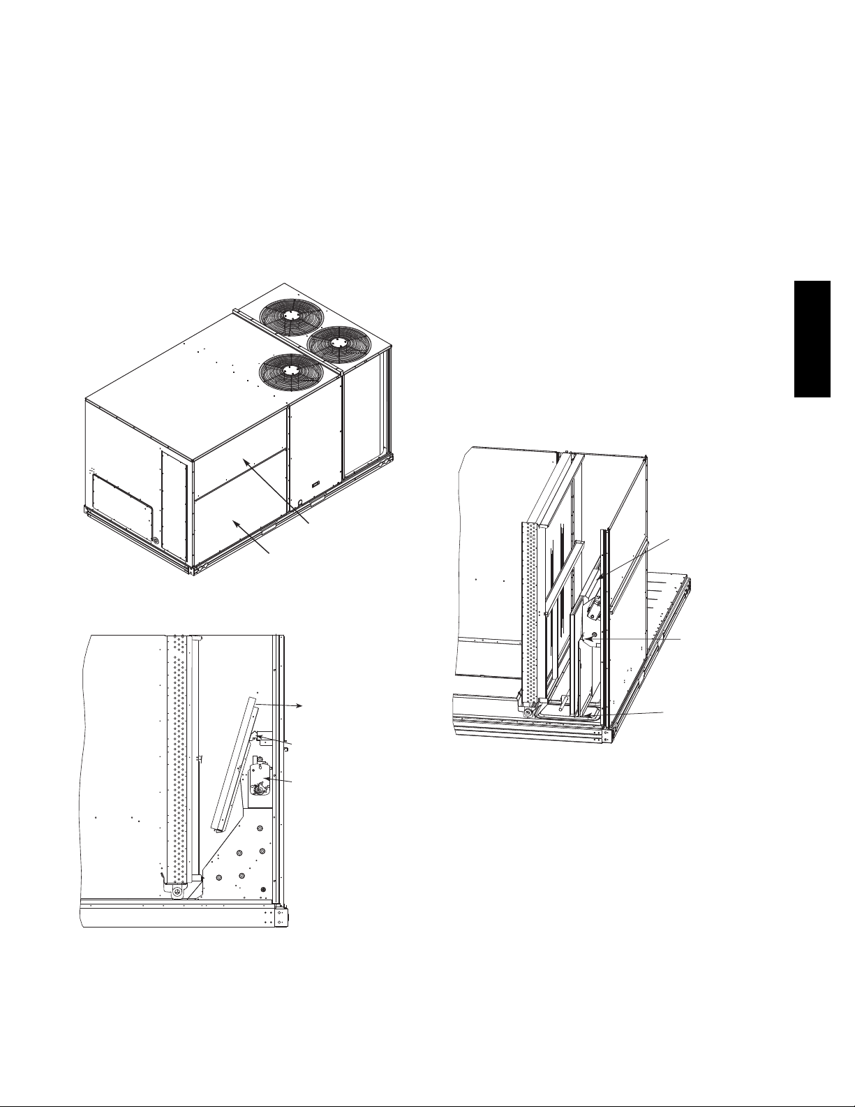
Step 8 — Install Outside Air Hood
Economizer Hood Removal and Setup -Factory Option —
1. The hood is shipped in knock--down form and located
in the return air compartment. It is attached to the
economizer using two plastic tie--wraps.
2. To gain access to the hood, remove the filter access
panel. (See Fig. 9.)
3. Locate and cut the (2) plastic tie--wraps, being careful
to not damage any wiring. (See Fig. 10.)
4. Carefully lift the hood assembly through the filter
access opening and assemble per the steps outlined in
Economizer Hood and Two–Position Hood on page 10.
Two Position Damper Hood Removal and Setup -Factory Option —
1. The hood is shipped in knock--down form and
assembled to a metal support tray using plastic stretch
wrap. Located in the return air compartment, the
assembly’s metal tray is attached to the basepan and
also attached to the damper using two plastic
tie--wraps.
2. To gain access to the hood, remove the filter access
panel. (See Fig. 9.)
3. Locate the (2) screws holding the metal tray to the
basepan and remove. In order to remove the screws, it
may be necessary to remove the panel underneath the
two--position damper. Remove the two screws. Locate
and cut the (2) plastic tie--wraps securing the
assembly to the damper. (See Fig. 11.) Be careful to
not damage any wiring or cut tie--wraps securing any
wiring.
4. Carefully lift the hood assembly (with metal tray)
through the filter access opening and assemble per the
steps outlined in Economizer Hood and Two–Position
Hood on page 10.
5. If removed, reattach the panel under the damper.
48TC**16
FILTER ACCESS PANEL
INDOOR COIL ACCESS PANEL
Fig. 9 -- Typical Access Panel Locations
Remove Hood Parts
Cut Plastic Ties
(2) Places
Economizer
Hood Parts
C10004
Plastic Tie Wrap
Qty (2)
Screws for Metal Tray
Qty (2)
C10006
Fig. 11 -- Two--Position Damper Hood Package Location
Fig. 10 -- Economizer Hood Package Location
C10005
9
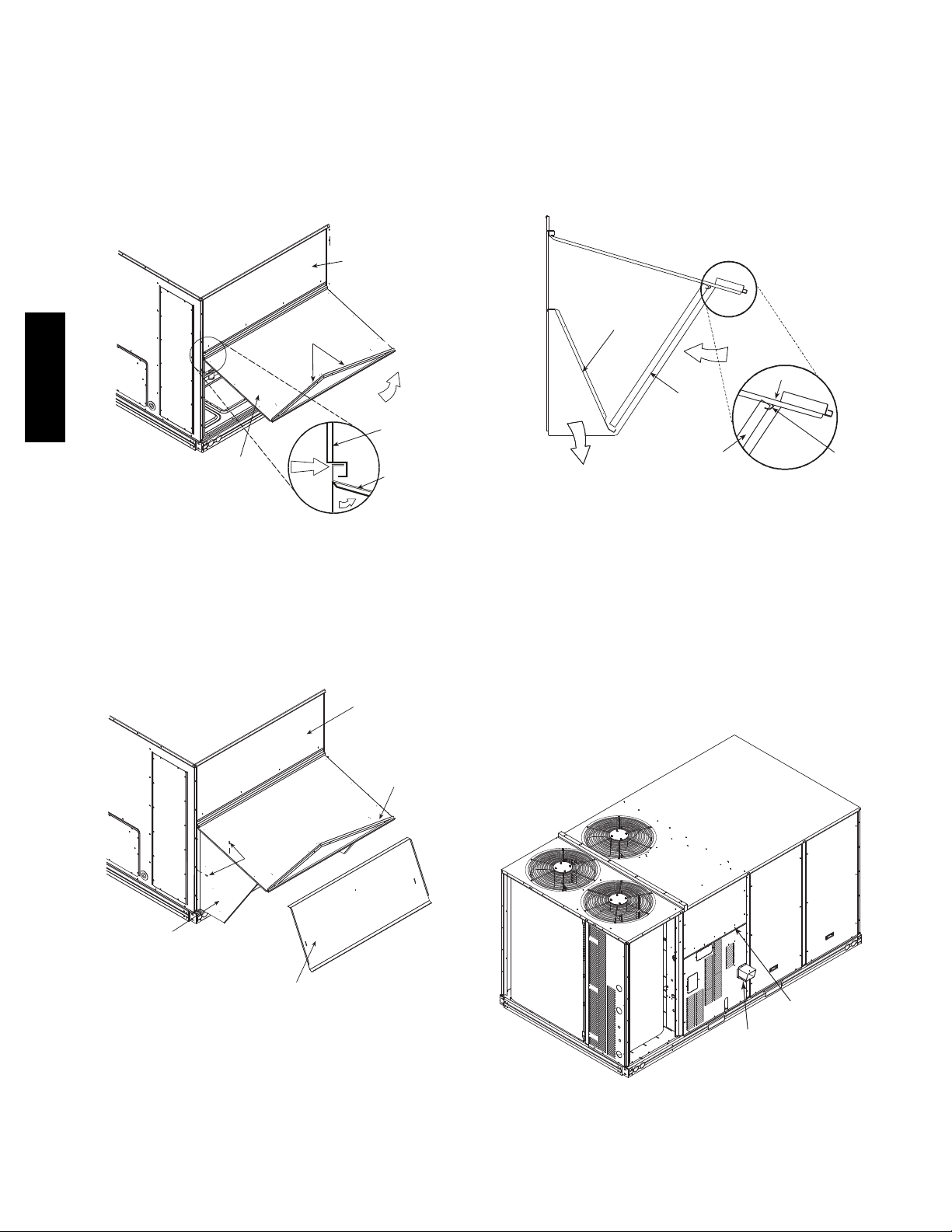
Economizer Hood and Two--Position Hood —
NOTE: If the power exhaust accessory is to be installed
on the unit, the hood shipped with the unit will not be
used and must be discarded. Save the aluminum filter for
use in the power exhaust hood assembly.
1. The indoor coil access panel will be used as the top of
the hood. If the panel is still attached to the unit, remove the screws along the sides and bottom of the
panel. See Fig. 12.
SIDE
PAN EL
5. Attach the post that separates the filters with the
screws provided.
6. Open the filter clips which are located underneath the
hood top. Insert the aluminum filters into the bottom
filter rack (hood divider). Push the filter into position
past the open filter clips. Close the filter clips to lock
the filters into place. See Fig. 14.
7. Install the two rain deflectors on the edge of the hood
topasshowninFig.12.
RAIN DEFLECTORS
48TC**16
CAULK
INDOOR
COIL
ACCESS
PAN EL
HERE
Fig. 12 -- Indoor Coil Access Panel Relocation
2. Swing out indoor coil access panel and insert the
hood sides under the panel (hood top). Be careful not
to lift the panel too far as it might fall out. Use the
screws provided to attach the hood sides to the hood
top. Use screws provided to attach the hood sides to
the unit. See Fig. 13.
TOP
PAN EL
TOP
PAN EL
INDOOR
COIL
ACCESS
PAN EL
C10007
BAROMETRIC
RELIEF
DIVIDER
CLEANABLE
ALUMINUM
FILTER
FILTER
OUTSIDE
AIR
HOOD
FILTER
CLIP
C10009
Fig. 14 -- Economizer Filter Installation
8. Caulk the ends of the joint between the unit top panel
and the hood top as shown in Fig. 12.
9. Replace the filter access panel.
Step 9 — Install Flue Hood
The flue hood is shipped screwed to the basepan beside
the burner compartment access panel. Remove the panel
below the control box access panel to access the flue hood
shipping location. Using screws provided, install flue
hood and screen in location shown in Fig. 15.
INDOOR COIL
ACCESS PANEL
SCREW
LEFT
HOOD
SIDE
HOOD DIVIDER
C10008
Fig. 13 -- Economizer Hood Construction
3. Remove the shipping tape holding the economizer
barometric relief damper in place.
4. Insert the hood divider between the hood sides. See
Figs. 13 and 14. Secure hood divider with 3 screws on
each hood side. The hood divider is also used as the
bottom filter rack for the aluminum filter.
CONTROL BOX
ACCESS PANEL
FLUE
HOOD
C10804
Fig. 15 -- Flue Hood Details
10
Step 10 — Install Gas Piping
R
Installation of the gas piping must be accordance with
local building codes and with applicable national codes.
In U.S.A., refer to NFPA 54/ANSI Z223.1 National Fuel
Gas Code (NFGC). In Canada, installation must be
accordance with the CAN/CSA B149.1 and CAN/CSA
B149.2 installation codes for gas burning appliances.
This unit is factory equipped for use with Natural Gas fuel
at elevations up to 2000 ft (610 m) above sea level. Unit
may be field converted for operation at elevations above
2000 ft (610 m) and/or for use with liquefied petroleum
fuel. See accessory kit installation instructions regarding
these accessories.
NOTE: In U.S.A. the input rating for altitudes above 2000
ft (610 m) must be derated by 4% for each 1000 ft (305 m)
above sea level. In Canada the input rating must be derated
by 10% for altitudes of 2000 ft (610 m) to 4500 ft. (1372 m)
above sea level.
For natural gas applications, gas pressure at unit gas
connection must not be less than 5 in. wg (1250 Pa) or
greater than 13 in. wg (3240 Pa) while the unit is operating.
For liquified petroleum applications, the gas pressure must
not be less than 11 in. wg (2740 Pa) or greater than 13 in.
wg (3240 Pa) at the unit connection.
The gas supply pipe enters the unit at the burner access
panel on the front side of the unit, through the long slot at
the bottom of the access panel. The gas connection to the
unit is made to the
valve.
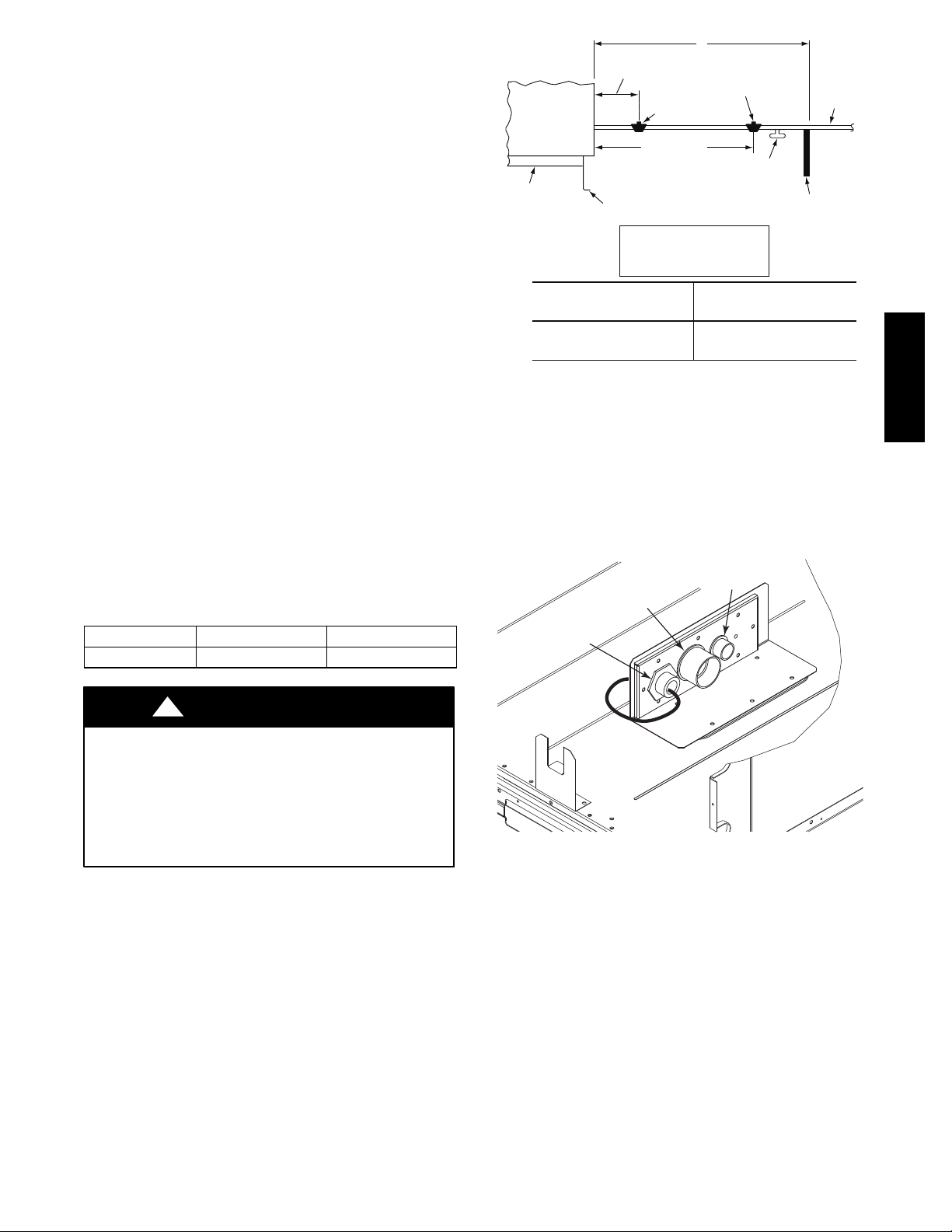
Table 2 – Natural Gas Supply Line Pressure Ranges
UNIT MIN MAX
48HC**14 5.0 in. wg (1250 Pa) 13.0 in. wg (3240 Pa)
3
/4--in. FPT gas inlet port on the unit gas
X
9” MINIMUM CLEARANCE
BASE UNIT
BASE RAIL
FOR PANEL REMOVAL
MANUAL GAS
SHUTOFF VALVE
48” MINIMUM
ROOF
CURB
NFGC – National Fuel Gas Code
Field supplied.
*
NOTE: Follow all local codes.
STEEL PIPE
NOMINAL DIAMETER
(in.)
1
/
2
3
/
or 1
4
1
/
or larger
1
4
LEGEND
GAS
REGULATOR
*
DRIP LEG
PER NFGC
FABRICATED
SPACINGOFSUPPORTS
X DIMENSION
(ft)
6
8
10
*
*
FIELD-
SUPPORT
FROM
GAS
METE
*
C11121
Fig. 16 -- Gas Piping Guide
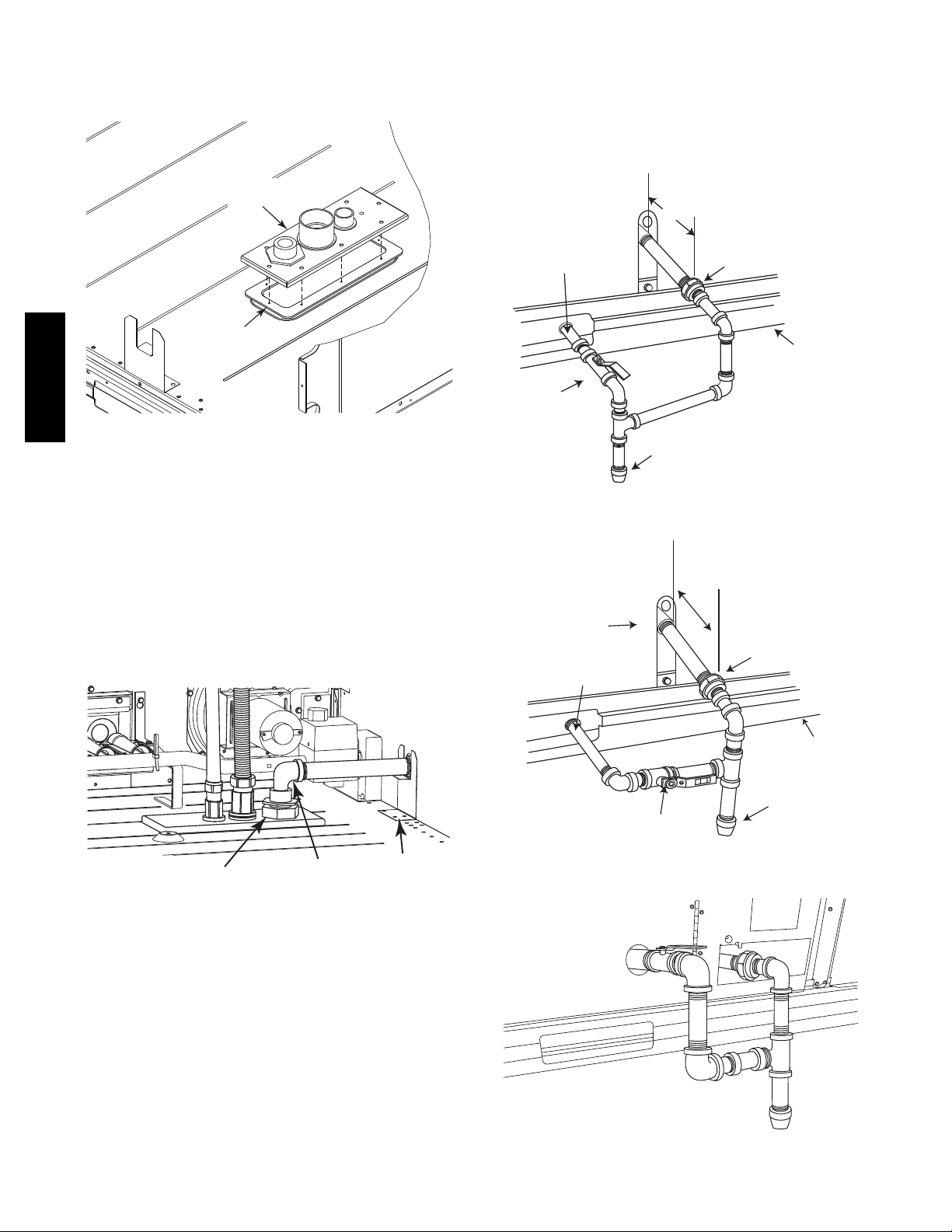
Factory--Option Thru--Base Connections
(Gas Connection) —
3
This service connection kit consists ofa
1
fitting (stainless steel), a
1
and a 1
/2--in electrical bulkhead connector, connected to an
/2--in electrical bulkhead connector
/4--in NPT gasadapter
“L” bracket covering the embossed (raised) section of the unit
basepan in the condenser section. See Fig. 17.
1
/2” ELECTRICAL
BULKHEAD
CONNECTOR
3
/4” NPT GAS
ADAPTER
FITTING
11/2” ELECTRICAL
BULKHEAD
CONNECTOR
48TC**16
!
CAUTION
EQUIPMENT DAMAGE HAZARD
Failure to follow this caution may result in damage
to equipment.
When connecting the gas line to the unit gas valve,
the installer MUST use a backup wrench to prevent
damage to the valve.
Install a gas supply line that runs to the unit heating
section. Refer to the NFPA 54/NFGC or equivalent code
for gas pipe sizing data. Size the gas supply line to allow
for a maximum pressure drop of 0.5--in wg (124 Pa)
between gas regulator source and unit gas valve
connection when unit is operating at high--fire flow rate.
The gas supply line can approach the unit in three ways:
horizontally from outside the unit (across the roof),
thru--curb/under unit basepan (accessory kit required) or
through unit basepan (factory--option or accessory kit
required). Consult accessory kit installation instructions
for details on these installation methods. Observe
clearance to gas line components per Fig. 16.
C10905
Fig. 17 -- Thru--the--Base Option, Shipping Position
1. Remove the “L” bracket assembly from the unit (see
Fig. 17).
2. Cut and discard the wire tie on the gas fitting. Hand
tighten the fitting if it has loosened in transit.
3. Remove connector plate assembly from the “L”
bracket and discard the “L” bracket, but retain the
washer head screws and the gasket (located between
the “L” bracket and the connector plate assembly
NOTE: Take care not to damage the gasket, as it is
reused in the following step.
4. Place the gasket over the embossed area in the
basepan, aligning the holes in the gasket to the holes
in the basepan. See Fig. 18.
5. Install the connector plate assembly to the basepan
using 8 of the washer head screws.
11
NOTE: If gas and/or electrical connections are not going to
occur at this time, tape or otherwise cover the fittings so that
moisture does not get into the building or conduit in the
interim.
CONNECTOR
PLATE
ASSEMBLY
shutoff valve be located upstream of the sediment trap.
See Figs. 20 and 21 for typical piping arrangements for
gas piping that has been routed through the sidewall of the
curb. See Fig. 22 for typical piping arrangement when
thru--base is used. Ensure that all piping does not block
access to the unit’s main control box or limit the required
working space in front of the control box.
9” (229mm) min
GASKET
48TC**16
Fig. 18 -- Completing Installation of Thru--the--Base
Option
The thru--base gas connector has male and female threads.
The male threads protrude above the basepan of the unit;
the female threads protrude below the basepan.
Check tightness of connector lock nuts before connecting
gas piping.
3
Install a
thru--base gas fitting. Attach a
/4--in NPT street elbow (field--supplied) on the
3
/4--in pipe nipple with
minimum length of 16--in (406 mm) (field--supplied) to
the street elbow and extend it through the access panel at
the gas support bracket. (See Fig. 19.)
C10906
Thru-Curb Adapter
Shut Off
Valve
Burner
Access
Panel
Thru-Curb Adapter
Union
Unit Base Rail
Drip
Leg
C07469
Fig. 20 -- Gas Piping
9” (229mm) min
Union
THRU-BASE
GAS FITTING
3
/4-in NPT
STREET
ELBOW
GAS
SUPPORT
BRACKET
C10806
Fig. 19 -- Gas Line Piping
Other hardware required to complete the installation of
the gas supply line will include a manual shutoff valve, a
sediment trap (drip leg) and a ground--joint union. A
pressure regulator valve may also be required (to convert
gas pressure from pounds to inches of pressure). The
manual shutoff valve must be located within 6--ft (1.83 m)
of the unit. The union, located in the final leg entering the
unit, must be located at least 9--in (230 mm) away from
the access panel to permit the panel to be removed for
service. If a regulator valve is installed, it must be located
a minimum of 4--ft (1220 mm) away from the unit’s flue
outlet. Some municipal codes require that the manual
Unit Base Rail
Drip
Leg
Shut Off
Val ve
C07470
Fig. 21 -- Gas Piping
C10826
Fig. 22 -- Gas Piping Thru--Base Connections
12
When installing the gas supply line, observe local codes
pertaining to gas pipe installations. Refer to the NFPA
54/ANSI Z223.1 NFGC latest edition (in Canada, CAN/CSA
B149.1). In the absence of local building codes, adhere to
the following pertinent recommendations:
1. Avoid low spots in long runs of pipe. Grade all pipe
1
/4--in. in every 15 ft (7 mm in every 5 m) to prevent
traps. Grade all horizontal runs downward to risers.
Use risers to connect to heating section and to meter.
2. Protect all segments of piping system against physical
and thermal damage. Support all piping with appropriate straps, hangers, etc. Use a minimum of one
hanger every 8 ft (2.4 m). For pipe sizes larger than
3
/4--in., follow recommendations of national codes.
3. Apply joint compound (pipe dope) sparingly and only
to male threads of joint when making pipe connections. Use only pipe dope that is resistant to action of
liquefied petroleum gases as specified by local and/or
national codes. If using PTFE (Teflon) tape, ensure
the material is Double Density type and is labeled for
use on gas lines. Apply tape per manufacturer’s instructions.
4. Pressure--test all gas piping in accordance with local
and national plumbing and gas codes before connecting piping to unit.
NOTE: Pressure test the gas supply system after the gas
supply piping is connected to the gas valve. The supply
piping must be disconnected from the gas valve during the
testing of the piping systems when test pressure is in
excess of 0.5 psig (3450 Pa). Pressure test the gas supply
piping system at pressures equal to or less than 0.5 psig
(3450 Pa). The unit heating section must be isolated from
the gas piping system by closing the external main manual
shutoff valve and slightly opening the ground--joint union.
Check for gas leaks at the field--installed and
factory--installed gas lines after all piping connections
have been completed. Use soap--and--water solution (or
method specified by local codes and/or regulations).
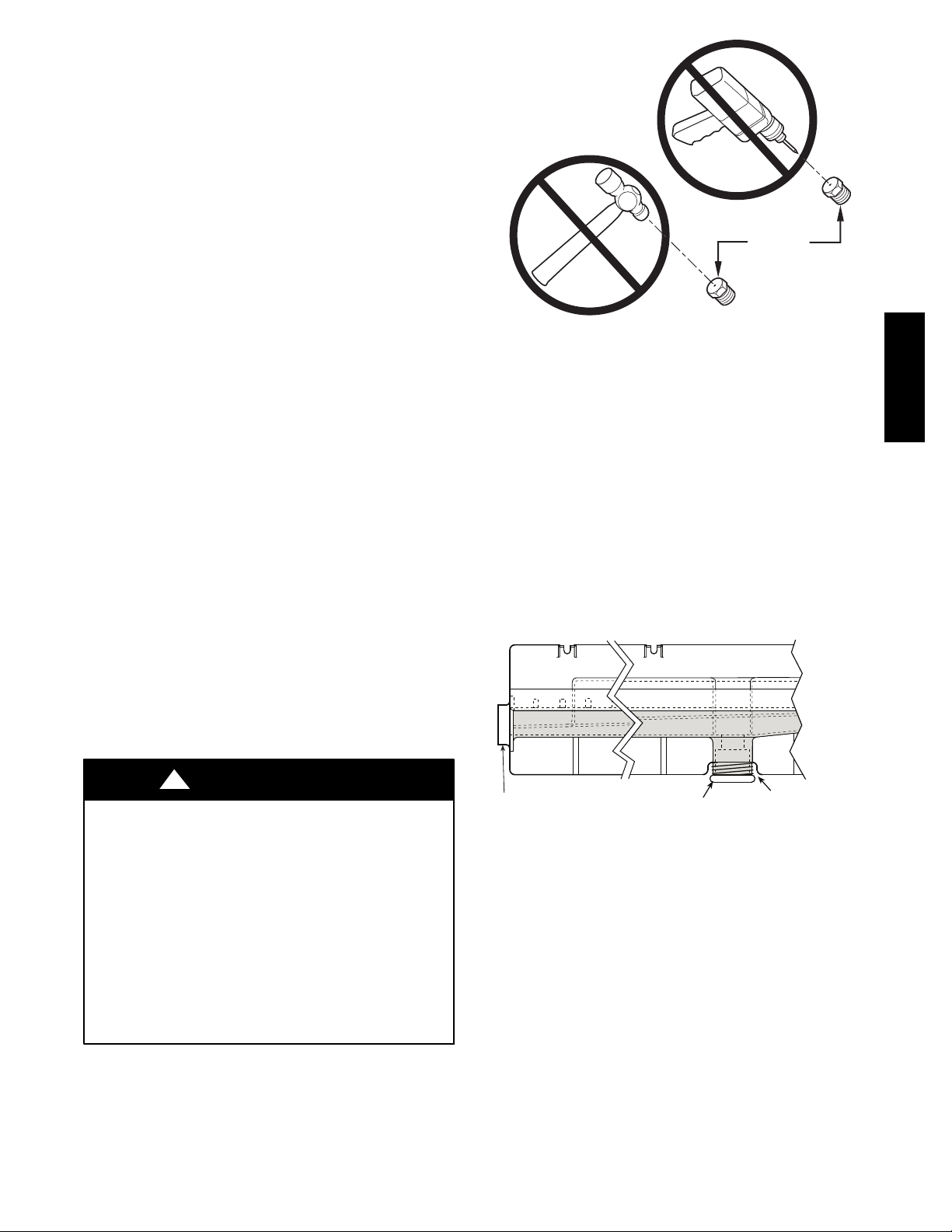
BURNER
ORIFICE
A93059
Fig. 23 -- Orifice Hole
NOTE: If orifice hole appears damaged or it is suspected
to have been re--drilled, check orifice hole with a
numbered drill bit of correct size. Never re--drill an
orifice. A burr--free and squarely aligned orifice hole is
essential for proper flame characteristics. See Fig. 23.
Step 11 — Install External Condensate Trap and
Line
The unit has one3/4-in. condensate drain connection on
the end of the condensate pan and an alternate connection
on the bottom. See Fig. 24. Unit airflow configuration
does not determine which drain connection to use. Either
drain connection can be used with vertical or horizontal
applications.
48TC**16
!
WARNING
FIRE OR EXPLOSION HAZARD
Failure to follow this warning could result in personal
injury, death and/or property damage.
S Connect gas pipe to unit using a backup wrench to
avoid damaging gas controls.
S Never purge a gas line into a combustion chamber.
S Never test for gas leaks with an open flame. Use a
commercially available soap solution made
specifically for the detection of leaks to check all
connections.
S Use proper length of pipe to avoid stress on gas
control manifold.
CONDENSATE PAN (SIDE VIEW)
STANDARD
SIDE DRAIN
DRAIN
PLUG
(FACTORY-INSTALLED)
ALTERNATE
BOTTOM DRAIN
C08021
Fig. 24 -- Condensate Drain Pan (Side View)
When using the standard side drain connection, ensure the
red plug in the alternate bottom connection is tight. Do
this before setting the unit in place. The red drain pan can
1
be tightened with a
/2--in. square socket drive extension.
To use the alternate bottom drain connection, remove the
red drain plug from the bottom connection (use a
1
/2-- i n .
square socket drive extension) and install it in the side
drain connection.
13

The piping for the condensate drain and external trap can
be completed after the unit is in place. See Fig. 25.
MINIMUM PITCH
1” (25mm) PER
10’ (3m) OF LINE
BASE RAIL
OPEN
VENT
2˝ (51) MIN
TO ROOF
DRAIN
DRAIN PLUG
NOTE: Trap should be deep enough to offset maximum unit static
difference. A 4” (102) trap is recommended.
Fig. 25 -- Condensate Drain Piping Details
48TC**16
All units must have an external trap for condensate
drainage. Install a trap at least 4-in. (102 mm) deep and
protect against freeze-up. If drain line is installed
downstream from the external trap, pitch the line away
from the unit at 1-in. per 10 ft (25 mm in 3 m) of run. Do
not use a pipe size smaller than the unit connection
3
/4-in.).
(
Step 12 — Make Electrical Connections
!
WARNING
ELECTRICAL SHOCK HAZARD
Failure to follow this warning could result in personal
injury or death.
Do not use gas piping as an electrical ground. Unit
cabinet must have an uninterrupted, unbroken electrical
ground to minimize the possibility of personal injury if
an electrical fault should occur. This ground may consist
of electrical wire connected to unit ground lug in control
compartment, or conduit approved for electrical ground
when installed in accordance with NEC (National
Electrical Code); ANSI/NFPA 70, latest edition (in
Canada, Canadian Electrical Code CSA [Canadian
Standards Association] C22.1), and local electrical
codes.
SEE NOTE
ROOF
CURB
C08022
Fig. 26 -- Conduit into Factory Option Disconnect
C10884
C10885
Fig. 27 -- Conduit into Control Box
If the field disconnect is larger than 100A, it must be
attached to the unit using accessory CRDISBKT001A00
— disconnect switch bracket — (see Fig. 28). Follow the
instructions provided with this accessory. For smaller field
1
disconnects, be sure to use
/2” screws to mount the
disconnect directly to the end panel (see Fig. 29). In either
case, set the disconnect vertical location on the unit so
that a 90_ fitting can be used to connect the conduit to the
disconnect.
NOTE: Field--supplied wiring shall conform with the
limitations of minimum 63_F(33_C) rise.
Field Power Supply —
For those units without through--the--curb power, conduit
must be used to route the main power from the condenser
end, via the power entry in the corner post of the unit (see
Figs. 26 and 27) to either the factory option disconnect or
the bottom of the control box. 1” conduit is provided
wrapped around compressor. A second conduit is provided
with factory installed powered convenience outlet. For those
units that require conduit larger than 1”, it must be field
supplied. Figs. 26 and 27 show the wire routings.
C10853
Fig. 28 -- Mounting Position for Field Disconnects
(over 100A)
14

C10854
Fig. 29 -- Mounting Position for Field Disconnects
(up to 100A)
Field power wires are connected to the unit at line--side
pressure lugs at the main terminal block (TB1) or at
factory--installed option non--fused disconnect switch.
Max wire size is #2 AWG (copper only). (See Fig. 31.)
NOTE: TEST LEADS -- Unit may be equipped with
short leads (pigtails) on the field line connection points off
the optional disconnect switch. These leads are for factory
run--test purposes only; remove and discard before
connecting field power wires to unit connection points.
Make field power connections directly to line connection
pressure lugs only.
!
WARNING
FIRE HAZARD
Failure to follow this warning could result in
intermittent operation or performance satisfaction.
Do not connect aluminum wire between disconnect
switch and unit. Use only copper wire.
(See Fig. 30.)
All Units —
All field wiring must comply with NEC and all local
requirements. Size wire based on MCA (Minimum Circuit
Amps) on the unit informative plate. See Fig. 31 and the
unit label diagram for power wiring connections to the
unit power terminal blocks and equipment ground.
Maximum wire size is 2/0 AWG per pole.
Provide a ground--fault and short--circuit over--current
protection device (fuse or breaker) per NEC Article 440
(or local codes). Refer to unit informative data plate for
MOCP (Maximum Over--current Protection) device size.
Voltage to compressor terminals during operation must be
within voltage range indicated on unit nameplate. See
Table 10. On 3--phase units, voltages between phases must
be balanced within 2% and the current within 10%. Use
the formula shown in the legend for Table 10 (see Note 2
on page 45) to determine the percent of voltage
imbalance.
All units except 208/230-v units are factory wired for the
voltage shown on the nameplate. If the 208/230-v unit is
to be connected to a 208-v power supply, the control
transformer must be rewired by moving the black wire
1
with the
connection and moving it to the 200-v
/4-in. female spade connector from the 230--v
1
/4-in. male
terminal on the primary side of the transformer. Refer to
unit label diagram for additional information.
!
CAUTION
UNIT DAMAGE HAZARD
Failure to follow this caution may result in equipment
damage.
Operation on improper line voltage or excessive phase
imbalance constitutes abuse and may cause damage to
electrical components. Such operation would invalidate
any applicable Carrier warranty.
NOTE: Check all factory and field electrical connections
for tightness.
Units Without Factory--Installed Disconnect —
48TC**16
ELECTRIC
DISCONNECT
SWITCH
Fig. 30 -- Disconnect Switch and Unit
COPPER
WIRE ONLY
ALUMINUM
WIRE
A93033
When installing units, provide a disconnect switch of
adequate size per NEC (National Electrical Code).
Disconnect sizing data is provided on the unit informative
plate. Locate on unit cabinet or within sight of the unit per
national or local codes. Do not cover unit informative
plate if mounting the disconnect on the unit cabinet.
Units with Factory--Installed Disconnect —
The factory--installed option disconnect switch is located in a
weatherproof enclosure located under the main control box.
The manual switch handle is accessible through an opening
in the access panel. Discard the factory test leads (see Fig.
31). The factory disconnect is an 80A disconnect.
15
 Loading...