


42 Series
Fan Coil Units
Application Data
Control Selection Guide for Fan Coil Air Conditioners
Manufacturer reserves the right to discontinue, or change at any time, speci®cations or designs without notice and without incurring obligations.
Book |
3 |
|
PC 201 |
Catalog No. 514-203 |
Printed in U.S.A. |
Form 42-3XC |
Pg 1 |
6-90 |
Replaces: 42-2XC |
Tab |
7a |
|
|
|
|
|
|
|
|
|
|
|
|
|
|
|
|
|
|
CONTENTS
Page
CONTROL SELECTION GUIDE . . . . . . . . . . . . . . . 3
STANDARD WIRING PACKAGES . . . . . . . . . . . . 4-8
Manual Fan Control . . . . . . . . . . . . . . . . . . . . . . . . . 4
Thermostatic Fan Control,
2-Pipe Systems . . . . . . . . . . . . . . . . . . . . . . . . . . . . 4
Thermostatic Fan Control,
2-Pipe System with Safety Cycle . . . . . . . . . . . . 5
Thermostatic Electric Valve Control, 2-Pipe . . . 5
Thermostatic 2-Pipe Auxiliary Electric Heat
with Valve Control . . . . . . . . . . . . . . . . . . . . . . . . . 6
Thermostatic 2-Pipe Total Electric Heat
with Valve Control . . . . . . . . . . . . . . . . . . . . . . . . . 7
Thermostatic Valve Control, 4-Pipe . . . . . . . . . . . 8
ELECTRIC HEAT . . . . . . . . . . . . . . . . . . . . . . . . . . . . 9
Application . . . . . . . . . . . . . . . . . . . . . . . . . . . . . . . . . 9
Heater Construction . . . . . . . . . . . . . . . . . . . . . . . . . 9
Heater Electrical Data . . . . . . . . . . . . . . . . . . . . . . . 9
REMOTE-MOUNTED CONTROLS . . . . . . . . . . . . 10
Standard 3-Speed Switch . . . . . . . . . . . . . . . . . . . 10
Combination Thermostat/3-Speed Switch . . . . 10
Wall Thermostat, 2-Pipe . . . . . . . . . . . . . . . . . . . . 10
Wall Thermostat, 4-Pipe . . . . . . . . . . . . . . . . . . . . 10
ALTERNATE WALL THERMOSTATS . . . . . . . . . 11
Wall Thermostat (Honeywell) with Manual 3-Speed Fan Switch and ON-OFF Switch . . . 11
Wall Thermostat (Sunne) with Manual
3-Speed Fan Switch and ON-OFF Switch . . . 11
Page
UNIT MOUNTED CONTROLS . . . . . . . . . . . . . . 12,13
Standard 3-Speed Switch . . . . . . . . . . . . . . . . . . . 12
Combination Thermostat/3-Speed Switch . . . . 12
Combination Thermostat/ON-OFF
Toggle Switch . . . . . . . . . . . . . . . . . . . . . . . . . . . . 12
Two-Pipe Thermostat . . . . . . . . . . . . . . . . . . . . . . . 13
Four-Pipe Thermostat . . . . . . . . . . . . . . . . . . . . . . 13
Automatic Changeover . . . . . . . . . . . . . . . . . . . . . 13
BASIC DEFINITIONS . . . . . . . . . . . . . . . . . . . . . . . |
14 |
FIELD PIPING CONNECTIONS . . . . . . . . . . . . . . |
15 |
VALVE PACKAGES . . . . . . . . . . . . . . . . . . . . . . . 16-19 General . . . . . . . . . . . . . . . . . . . . . . . . . . . . . . . . . . . 16
Two-Way Motorized Control Valve . . . . . . . . . . . 18
Two-Way Motorized Control Valve
with Aquastat Bleed Bypass Line . . . . . . . . . . 18 Three-Way Motorized Control Valve . . . . . . . . . 19 No Motorized Control Valve . . . . . . . . . . . . . . . . . 19
VALVE PACKAGE ARRANGEMENTS . . . . . . . 20-23
PIPING COMPONENTS . . . . . . . . . . . . . . . . . . . . 24-27
Cv FACTOR vs WATER PRESSURE DROP . . . 28
SYSTEM COMPONENT WORKING
PRESSURE . . . . . . . . . . . . . . . . . . . . . . . . . . . . . . . 29
COPPER WATER TUBE AND JOINT MATERIAL PRESSURE RATINGS . . . . . . . . . . . . . . . . . . . . . 30
CORRECTION FACTORS FOR GLYCOL . . . . . . 31 STANDARD ACCESSORIES AND OPTIONS . . 32
2
CONTROL SELECTION GUIDE
Use this guide to make sure that all necessary components are provided for and that the components are compatible with the required control system.
NOTE: When thermostatic fan control is selected or when unit outside air dampers are used, unit-mounted thermostats are not recommended as their use will result in poor room temperature sensing.
|
|
|
|
CHANGEOVER |
|
FAN |
|
|
|
SYSTEM |
DESCRIPTION |
THERMOSTAT |
ON |
VALVE |
NOTES |
||
|
SWITCH (SW) |
|||||||
|
|
|
|
SUPPLY PIPE |
|
|
||
|
|
|
|
|
|
|
||
|
Fan |
Fan manually cycled |
None |
None |
None |
Standard |
Not recommended |
|
|
Control |
|
|
|
|
3-Speed SW |
for high humidity |
|
|
(2-Pipe) |
|
|
|
|
|
application |
|
|
Thermostat cycles fan on-off |
Wall mounted |
None |
None |
Thermostat has |
|||
|
|
|
||||||
|
|
from speed set with |
includes heat-cool |
|
|
integral |
|
|
|
|
fan switch. |
switch. |
|
|
3-Speed SW |
|
|
|
|
Thermostat cycles fan on-off |
Wall mounted. |
Yes |
None |
Standard |
Unit mounted |
|
|
|
from fan speed set |
Heating/cooling |
|
|
3-Speed SW |
thermostats provide |
|
|
|
with switch. Mode |
Thermostat |
|
|
|
very poor room |
|
-COOLING* |
|
automatically switched |
|
|
|
|
temperature control |
|
|
by changeover |
|
|
|
|
|
||
|
sensing water temp. |
|
|
|
|
|
||
|
Thermostat cycles fan from |
Wall or unit |
Yes |
None |
No Standard |
Best fan cycle |
||
|
high to low on cooling |
mounted |
|
|
3-Speed Switch, |
control for |
||
|
and low to off on heating. |
|
|
|
ON-OFF toggle SW |
high humidity |
||
HEATING |
|
|
|
|
||||
|
|
|
|
|
only |
applications |
||
Two- |
Thermostat cycles valve |
Wall mounted |
None |
Motorized (N.C.) |
Thermostat |
Valve packages |
||
position |
open or closed. |
includes heat-cool |
|
3-way or 2-way, |
has integral |
with belled end(s) |
||
electric |
|
switch. |
|
no bypass required. |
3-Speed SW |
for ®eld soldering |
||
PIPE |
valves |
|
|
|
|
|
to coil. |
|
Thermostat cycles valve |
Wall or unit |
Yes |
Motorized (N.C.) |
Standard |
||||
(2-pipe) |
|
|||||||
open or closed. |
mounted. |
|
3-way or 2-way |
3-Speed SW. |
|
|||
2- |
|
Mode automatically |
Heating/cooling |
|
|
Others have |
|
|
|
|
|
|
|
||||
|
|
switched by changeover |
Thermostat |
|
|
thermostats with |
|
|
|
|
sensing water temp. |
|
|
|
integral 3-Speed SW |
|
|
|
Pneumatic |
Thermostat modulates |
By others. |
By others. |
2- and 3-way |
Standard |
Factory assembled |
|
|
modulating |
pneumatic control valve. |
|
|
furnished by others. |
3-Speed SW |
in valve package |
|
|
valves |
|
|
|
Can be equipped |
|
w/¯are nuts. |
|
|
(2-pipe) |
|
|
|
with factory |
|
Valve packages |
|
|
|
|
|
|
assembled |
|
with belled end(s) |
|
|
|
|
|
|
valve package. |
|
for ®eld soldering |
|
|
|
|
|
|
|
|
to coil. |
|
|
Two- |
Thermostat cycles valve |
Wall or unit |
Yes. |
Motorized |
Standard |
Valve packages |
|
|
position |
open or closed. 2° F after |
mounted. Sequenced |
Two Required. |
3-way or 2-way |
3-Speed SW |
with belled end(s) |
|
|
electric |
valve closes, thermostat |
heating and cooling. |
|
|
Others have |
for ®eld soldering |
|
|
valve with |
activates electric heater. |
|
|
|
thermostats with |
to coil. |
|
|
Auxiliary |
Heater can't turn on |
|
|
|
integral 3-Speed SW |
|
|
|
Electric |
if hot water is in coil. |
|
|
|
|
|
|
|
Heat |
|
|
|
|
|
|
|
|
Thermostat cycles valve |
Wall mounted |
None |
Motorized |
Thermostat |
Valve packages |
||
|
(2-pipe) |
|||||||
|
open or closed. Manual |
includes heat-cool |
|
3-way or 2-way, |
has integral |
with belled end(s) |
||
|
|
|
||||||
|
|
changeover switch |
switch. |
|
no bypass required |
3-Speed SW |
for ®eld soldering |
|
|
|
changes thermostat to |
|
|
|
|
to coil. |
|
HEAT |
|
heat to activate electric |
|
|
|
|
|
|
|
heater. |
|
|
|
|
|
||
Two- |
Thermostat cycles valve |
Wall mounted |
None |
Motorized (N.C.) |
Thermostat |
Valve packages |
||
ELECTRIC |
position |
open or closed. |
includes heat-cool |
|
3-way or 2-way, |
has integral |
with belled end(s) |
|
electric |
Manual changeover switch |
switch. |
|
no bypass required |
3-Speed SW |
for ®eld soldering |
||
valve with |
changes thermostat to heat |
|
|
|
|
to coil. |
||
total |
to activate electric heater. |
|
|
|
|
|
||
electric |
|
|
|
|
|
|
||
Thermostat cycles valve |
Wall or unit |
None |
Motorized (N.C.) |
Standard |
|
|||
|
heat |
open or closed. |
mounted. |
|
3-way or 2-way, |
3-Speed SW |
|
|
|
(2-pipe) |
|
|
|||||
|
2° F after valve closes, |
Sequenced heating |
|
no bypass required |
|
|
||
|
|
|
|
|
||||
|
|
thermostat activates |
and cooling |
|
|
|
|
|
|
|
electric heater. |
|
|
|
|
|
|
|
Pneumatic |
Thermostat modulates |
By others. |
By others. |
2- and 3-way |
Standard |
Factory assembled |
|
|
modulating |
pneumatic control valve. |
|
|
furnished by others. |
3-Speed SW |
in valve package |
|
|
valves |
After changeover, |
|
|
Can be equipped |
|
w/¯are nuts. |
|
|
(2-pipe) |
thermostat |
|
|
with factory |
|
Valve packages |
|
|
|
activates electric heater. |
|
|
assembled |
|
with belled end(s) |
|
|
|
|
|
|
valve package. |
|
for ®eld soldering |
|
|
|
|
|
|
|
|
to coil. |
|
|
Two- |
Thermostat cycles |
Wall mounted |
None |
Motorized (N.C.) |
Thermostat |
Valve packages |
|
|
position |
cooling and heating |
includes subbase |
|
3-way or 2-way |
has integral |
with belled end(s) |
|
|
electric |
valves open or closed. |
with heat-cool |
|
(requires 2 valves) |
3-Speed SW |
for ®eld soldering |
|
|
valves |
|
switch. |
|
|
|
to coil. |
|
|
(4-pipe) |
|
|
|
|
|
|
|
|
Thermostat cycles cooling |
Wall or unit |
None |
Motorized (N.C.) |
Standard |
|
||
|
|
|
||||||
|
|
valve open or closed. 2° F |
mounted. |
|
3-way or 2-way |
3-Speed SW. |
|
|
PIPE |
|
after valve closes, |
Sequenced heating |
|
(requires 2 valves) |
Others have |
|
|
|
thermostat cycles |
and cooling. |
|
|
thermostats |
|
||
|
heating valve open or closed. |
|
|
|
with integral |
|
||
4- |
|
|
|
|
|
3-Speed SW |
|
|
|
Pneumatic |
Thermostat modulates |
By others. |
By others. |
2- or 3-way |
Standard |
Factory assembled |
|
|
modulating |
cooling valve. |
|
|
furnished by others. |
3-Speed SW |
in valve package |
|
|
valves |
After changeover, |
|
|
Can be equipped |
|
w/¯are nuts. |
|
|
(4-pipe) |
thermostat modulates |
|
|
with factory |
|
Valve packages |
|
|
|
heating valve. |
|
|
assembled |
|
include unions for |
|
|
|
|
|
|
valve package. |
|
for ®eld assembly |
|
|
|
|
|
|
|
|
to coil. |
*If system is HEATING-ONLY or COOLING-ONLY, no changeover or bypass is required.
NOTE: Unit-mounted thermostats are not recommended with either fan-cycle control or applications with outside air dampers.
3

STANDARD WIRING PACKAGES
IMPORTANT: Wiring diagrams shown depict typical control functions. Refer to unit wiring label for speci®c functions.
Manual Fan Control Ð On all Vertical Cabinet units, the standard fan-speed switch is furnished unit-mounted and wired. On all Vertical Furred-In units and all Horizontal units, the switch is shipped separately on a decorative wall plate for ®eld mounting and wiring.
The standard switch has LOW, MEDIUM, HIGH and OFF positions plus an auxilliary contact to energize thermostats, valves, dampers, etc.
NOTE: Wiring diagrams are for 120-v power supply. If other voltages for heaters or controls are speci®ed, wiring may differ from that shown.
The standard 3-speed switches are illustrated on page 12 (unit mounted) and on page 10 (wall mounted).
For NOTES, see below.
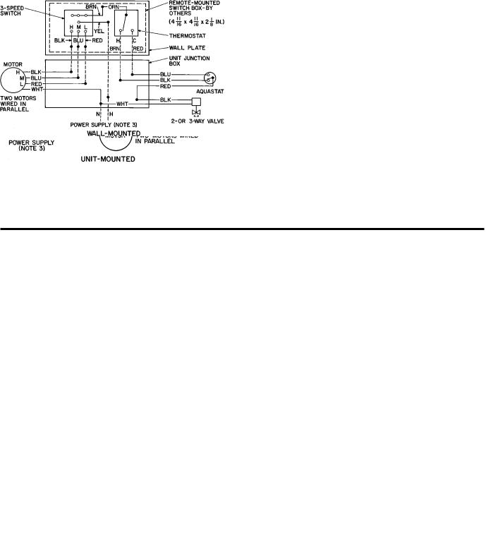
Thermostatic Fan Control, 2-Pipe Systems Ð |
UNIT |
|
|
|
THERMOSTAT OR |
|
The thermostat cycles the fan on and off from any selected |
|
LOCATION |
|
WIRING PACKAGE* |
||
TYPE |
|
|
Heating or |
Heating and Cooling |
||
speed setting to maintain selected room temperature. Con- |
|
|
|
|||
|
|
|
Cooling Only |
Plus Changeover² |
||
trols can be wired for heating-only, cooling-only or for heating/ |
|
|
|
|||
Vertical |
|
Unit Mounted |
|
N/A |
N/A |
|
cooling by the addition of an automatic changeover device |
|
|
||||
Vertical |
|
|
|
|
|
|
that senses water temperature and changes the action of the |
|
|
|
22-C, 22-D |
|
|
or |
|
Wall Mounted |
|
22-A, 22-B |
||
thermostat as required. |
|
|
22-E, 22-F |
|||
Horizontal |
|
|
|
|
||
For control package descriptions, see control components |
|
|
|
|
|
|
*Packages |
listed on current |
price pages. First 2 digits are item |
||||
sections entitled Remote-Mounted Controls and Unit- |
numbers. |
|
|
|
|
|
Mounted Controls, pages 10-13. |
²For alternate thermostat with manual changeover. Refer to current |
|||||
|
price pages. |
|
|
|||
NOTES:
1.Motors are thermally protected.
2.Use copper conductors only.
3.See unit nameplate for power supply. Provide disconnect means and overload protection as required.
4.Unit-mounted thermostats are not recommended for fan control because of poor temperature sensing. Fan control not available on 42VC,VE Loboy units.
4
Thermostatic Fan Control, 2-Pipe System with Safety Cycle Ð This control is used for high humidity situations in which condensate problems can occur if fan is turned off while chilled water is still running through the coil.
The wiring provides fan cycling from HIGH to LOW on the cooling cycle and from LOW to OFF on the heating cycle. An ON-OFF toggle switch replaces the standard 3-speed fan switch. The toggle switch can be concealed to ensure that the unit runs on low speed when cooling. This action greatly reduces the chance of condensation problems that exist with other standard fan cycling controls.
For control package descriptions, see control components section entitled Remote-Mounted Controls and Unit-Mounted Controls.
For NOTES, see below.
UNIT |
|
PACKAGE CODE* |
|
LOCATION |
Heating and Cooling |
||
TYPE |
|||
|
Plus Changeover |
||
|
|
||
Vertical |
Unit Mounted |
24-R |
|
Vertical |
|
|
|
or |
Wall Mounted |
23-17 |
|
Horizontal |
|
|
* Packages listed on current price pages.
Thermostatic Electric Valve Control, 2-Pipe Ð
A thermostatically controlled 2-position valve provides superior control to fan cycling. With this control, the fan runs continuously unless it is manually switched to the OFF position. The fan must be on before the valve can be opened to supply water to the coil.
This system can be used for normal 2-pipe changeover systems and can also be furnished for cooling-only or heatingonly applications by omitting the changeover and specifying which application is intended.
For control package descriptions, see control components sections entitled Remote-Mounted Controls and UnitMounted Controls.
|
|
THERMOSTAT OR |
|
||
|
|
WIRING PACKAGE* |
|
||
UNIT |
LOCATION |
Heating or |
Heating and |
ELECTRIC |
|
TYPE |
Cooling |
VALVE |
|||
|
Cooling |
||||
|
|
Plus |
|
||
|
|
Only |
|
||
|
|
Changeover² |
|
||
|
|
|
|
||
Vertical |
Unit |
24-M, |
24-L |
Any 2- or |
|
Mounted |
24-N |
3-way, |
|||
|
|
||||
|
|
|
|
2-position |
|
Vertical |
|
|
|
||
Wall |
22-C, 22-D, |
|
valve |
||
or |
22-A, 22-B |
package. |
|||
Mounted |
22-E, 22-F |
||||
Horizontal |
|
|
|||
|
|
|
|
||
|
|
|
|
|
|
*Packages listed on current price pages. First 2 digits are item numbers.
²For alternate thermostat with manual changeover. Refer to current price pages.
NOTES:
1.Motors are thermally protected.
2.Use copper conductors only.
3.See unit nameplate for power supply. Provide disconnect means and overload protection as required.
5

STANDARD WIRING PACKAGES (cont)
Thermostatic 2-Pipe Auxiliary Electric Heat with Valve Control Ð This system, also called Twilight or Intermediate Season electric heat, goes a long way towards solving the spring and fall control problems of 2-pipe systems.
You can run chilled water late into the fall, turn it on early in the spring and still have heat available to all units whenever required.
In winter the system is switched over to hot water. Two changeover devices are required for this. One device switches the action of the thermostat and the other locks out the electric heat when hot water is in the coil.
With this system, the fan runs continuously unless manually switched to OFF position. Fan must be on before thermostat can send signal to open chilled water valve or turn on electric heater.
Two control methods are available:
1.Use the standard automatic changeover thermostat with a dead band between heating and cooling, or Ð
2.Use a manual changeover thermostat. With this method only one changeover is required.
Be sure to include a 2-way or 3-way electric valve with this system.
NOTE: Wiring diagrams are for 120-v power supply. If other voltages for heaters or controls are speci®ed,wiring may differ from that shown.
For control package descriptions, see control components sections entitled Remote-Mounted Controls and UnitMounted Controls.
UNIT |
LOCATION |
WIRING PACKAGE* |
ELECTRIC |
||
TYPE |
Automatic System |
Manual System |
VALVE |
||
|
|||||
Vertical |
Unit |
24-Q |
Available on Special Order. |
|
|
Mounted |
Any 2- or 3-way, |
||||
|
|
|
|||
Vertical |
|
22-J, 22-K, |
|
2-position valve |
|
or |
Wall Mounted |
23-15, 23-16 |
Package. |
||
23-09, 23-10 |
|||||
Horizontal |
|
|
|
||
|
|
|
|
||
|
|
|
|
|
|
*Packages on current price pages.
NOTES:
1.Motors are thermally protected.
2.Use copper conductors only.
3.See unit nameplate for power supply. Provide disconnect means and overload protection as required.
6

Thermostatic 2-Pipe Total Electric Heat withValve Control Ð With this system, the complete heating requirement for the space is provided by the electric heater; the water system is never changed over for heating. It is therefore possible, just as with 4-pipe systems, to have heating or cooling at any time of the year.
The fan runs continuously unless it is manually switched to OFF position. Fan must be on before thermostat can send signal to open chilled water valve or turn on electric heater.
Normally, an automatic changeover thermostat with a dead band between heating and cooling is used, but a manual
changeover thermostat is also suitable. A 2-way or 3-way valve must also be used so that the chilled water is off whenever the heater is on. No changeover device to sense water temperature is necessary.
NOTE: Wiring diagrams are for 120-v power supply. If other voltages for heaters or controls are speci®ed, wiring may differ from that shown.
For control package descriptions, see control components sections entitled Remote-Mounted Controls and UnitMounted Controls.
UNIT |
LOCATION |
WIRING PACKAGE* |
ELECTRIC |
||
TYPE |
Automatic System |
Manual System |
VALVE |
||
|
|||||
Vertical |
Unit |
24-Q |
Available on Special Order. |
|
|
Mounted |
Any 2- or 3-way, |
||||
|
|
|
|||
Vertical |
|
22-J, 22-K, |
|
2-position valve |
|
or |
Wall Mounted |
23-15, 23-16 |
Package. |
||
23-09, 23-10 |
|||||
Horizontal |
|
|
|
||
|
|
|
|
||
*Packages on current price pages.
NOTES:
1.Motors thermally protected.
2.Use copper conductors only.
3.See unit nameplate for power supply. Provide disconnect means and overload protection as required.
7

STANDARD WIRING PACKAGES (cont)
Thermostatic Valve Control, 4-Pipe Ð The 4-pipe system provides the ultimate in economy and room temperature control. Both hot water and chilled water are available at any time.
Normally an automatic changeover thermostat is used, but a manual changeover thermostat is also suitable. Two 2-way valves, two 3-way valves, or one 2-way plus one 3-way valve must be selected. An automatic changeover device to sense water temperature is not required.
With this system, the fan runs continuously unless it is manually switched to OFF position. Fan must be on before thermostat can send signal to open the chilled water or hot water valve.
NOTE: Wiring diagrams are for 120-v power supply. If other voltages for heaters or controls are speci®ed, wiring may differ from that shown.
For control package descriptions, see control components sections entitled Remote-Mounted Controls and UnitMounted Controls.
UNIT TYPE |
LOCATION |
WIRING PACKAGE* |
ELECTRIC |
||
Automatic System |
Manual System |
VALVE |
|||
|
|
||||
Vertical |
Unit Mounted |
24-P |
Available on Special Order. |
Any 2- or 3-way, |
|
Vertical |
|
|
|
||
|
22-G, 22-H, |
|
2-position valve |
||
or |
Wall Mounted |
23-13, 23-14 |
|||
23-07, 23-08 |
package. |
||||
Horizontal |
|
|
|||
|
|
|
|
||
|
|
|
|
|
|
*Packages on current price pages.
NOTES:
1.Motors thermally protected.
2.Use copper conductors only.
3.See unit nameplate for power supply. Provide disconnect means and overload protection as required.
8
ELECTRIC HEAT
Application Ð Electric heaters are available for in-stallation on Carrier fan coil units in the following applications.
TOTAL ELECTRIC HEAT Ð This system provides complete heating during the heating season; no boiler is required. Heating and cooling are now available on an individual basis throughout the year with a 2-pipe system.
Chilled water is used for cooling and the electric heater is used for heating. Room controls can be supplied for either manual or automatic changeover.
AUXILIARY ELECTRIC HEAT Ð This system is used for heating between seasons or during the cooling season when chilled water is being circulated. Individual room controls are supplied to provide electric heat only when chilled water is being circulated through the system. Water ¯ow through the unit is shut off when the heater is turned on.
During the winter heating season, heating is provided by hot water circulated through the system. A changeover device locks out the electric heat when the hot water is circulated.
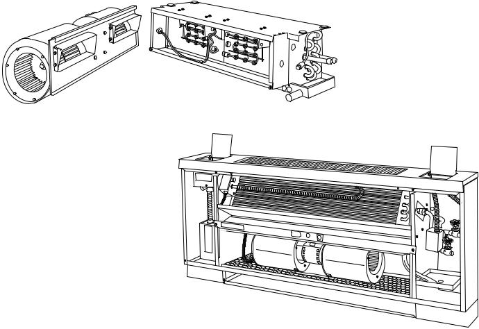
Heater Construction
STRIP HEATERS Ð Used with Model 42C ceiling units, Model 42D ducted units and Model 42S stack units.
These heaters consist of coils of the highest grade resistance wire, insulated by ceramic insulators in aluminized brackets.
All heaters except those used in 42S stack units are positioned on the incoming (preheat) side of the unit coil. On
MODEL 42V VERTICAL UNIT
WITH ELECTRIC SHEATH HEATER
42S stack units, the strip heater is located in the fan discharge on the leaving side of the coil.
SHEATH HEATERS Ð Used with Model 42V vertical units. These heaters consist of the highest grade resistance wire, centered in a 1¤2-in. diameter copper-plated steel sheath. The wire is insulated from the sheath by magnesium oxide powder packed around it. To increase the heater surface exposed to air, a 11¤4-in. OD ®n of copper-plated steel is wound around the sheath in a continuous spiral that makes 5 turns per lineal inch. Sheath and ®n are permanently bonded together by copper brazing.
The heaters are positioned on the leaving (reheat) side of the unit coil. On special units with high efficiency motors, a strip heater will be installed in the fan discharge on the incoming (preheat) side of the unit coil.
Heater Electrical Data
1.Load voltage may be 120, 208, 240 or 277 volts. For unit size and kW limitations, refer to the speci®c unit catalogs.
2.All heaters are single stage and single phase.
3.Unless a single power-source option is selected, the electric heat units require 2 separate power sources. With the single power-source option, only one line circuit need be brought into the unit. Fuse protection is added to the motor/ control circuit to protect these components. This is separate from the ®eld-furnished total unit overcurrent protection.
MODEL 42C CEILING UNIT
WITH ELECTRIC STRIP HEATER
9
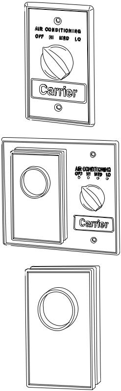
REMOTE-MOUNTED CONTROLS
Standard 3-Speed Switch Ð This standard switch has 4 positions: OFF, HIGH, MEDIUM, and LOW. Switch has auxiliary contact that is energized when switch is in HIGH, MEDIUM or LOW position.
Some of the options common with the 3-speed switch are:
1.Unit-mounted switch on Furred-In Vertical Model. (Available as special order on Horizontal Models)
2.Switch without OFF position.
3.Key-operated switch.
Combination Thermostat/3-Speed Switch
(Packages 22-B, 22-D, 22-F, 22-H, 22-K*) Ð Thermostat and standard switch are mounted on a common decorative wall plate, suitable for installation in a 411¤16-in. square junction box. Packages 22-A and 22-B include Model TC-126 2-pipe heating and cooling thermostat and automatic changeover switch (shipped separately for ®eld wiring and mounting).
Packages 22-C and 22-D include Model TC-126 thermostat less automatic changeover switch wired for cooling only.
Packages 22-E and 22-F include Model TC-126 thermostat, less automatic changeover, wired for heating only.
Package 22-G includes Model TH-126 4-pipe thermostat for sequenced heating and cooling, plus 3-speed switch. (For 4-pipe or total electric heat systems.)
Package 22-J is the same as 22-G except that 2 automatic changeover switches are shipped with package. (For auxiliary electric heat systems.)
Wall Thermostat, 2-Pipe (Packages 22-A through 22-F*) Ð Model TC-126 thermostat for heating and cooling, operates on line voltage. Action is SPDT. Temperature range is 50-90 F.
Packages 22-A and 22-B Ð Heating and cooling, includes one automatic changeover switch (shipped separately for ®eld wiring and mounting).
Wall Thermostat, 4-Pipe (Packages 22-G through 22-K*) Ð Model TH-126 thermostat is also used on 2-pipe system with electric heat. Heating and cooling are sequenced (automatic changeover) with 6 degree separation between HEATING ON and COOLING ON. Temperature range is 50 - 90 F.
Packages 22-G and 22-H Ð For 4-pipe and total electric heat systems.
Packages 22-J and 22-K Ð For auxiliary electric heat systems, includes 2 automatic changeover switches (shipped separately for ®eld wiring and mounting).
* Packages listed on current price pages.
|
60 |
70 |
|
80 |
|
|
|
|
50 |
|
90 |
|
|
60 |
70 |
80 |
|
50 |
90 |
|
Thermostat Electrical Data
(Pilot Duty Ð 125 VA)
VOLTS |
HEATING |
COOLING |
|||
FLA |
LRA |
FLA |
LRA |
||
|
|||||
120 |
5.8 |
34.8 |
5.8 |
34.8 |
|
240 |
4.9 |
29.4 |
4.9 |
29.4 |
|
277 |
4.1 |
24.6 |
4.1 |
24.6 |
|
|
|
|
|
|
|
10
 Loading...