


48TM016-028
Manufacturer reserves the right to discontinue, or change at any time, specifications or designs without notice and without incurring obligations.
Catalog No. 04-53480016-01 Printed in U.S.A. Form 48TM-4SI Pg 1 3-06 Replaces: 48TM-3SI
Book 1 4
Ta b 1 a 6 a
Installation, Start-Up and Service Instructions
CONTENTS
Page
SAFETY CONSIDERATIONS
........................1
INSTALLATION ..................................2-32
Step 1 — Provide Unit Support.....................2
• ROOF CURB
• ALTERNATE UNIT SUPPORT
Step 2 — Rig and Place Unit .......................2
• POSITIONING
• ROOF MOUNT
Step 3 — Field Fabricate Ductwork
...............11
Step 4 — Make Unit Duct Connections ...........11
Step 5 — Install Flue Hood and Wind Baffle ......11
Step 6 — Trap Condensate Drain .................11
Step 7 — Orifice Change ..........................12
Step 8 — Install Gas Piping .......................13
Step 9 — Make Electrical Connections ...........13
• FIELD POWER SUPPLY
• FIELD CONTROL WIRING
• OPTIONAL NON-FUSED DISCONNECT
• OPTIONAL CONVENIENCE OUTLET
Step 10 — Make Outdoor-Air Inlet
Adjustments
.....................................16
• MANUAL OUTDOOR-AIR DAMPER
Step 11 — Install Outdoor-Air Hood
..............16
Step 12 — Install All Accessories ............... 17
• MOTORMASTER® I CONTROL INSTALLATION
• MOTORMASTER V CONTROL INSTALLATION
Step 13 — Adjust Factory-Installed Options..... 19
• PREMIERLINK™ CONTROL
• ENTHALPY SWITCH/RECEIVER
• OUTDOOR ENTHALPY CONTROL
• DIFFERENTIAL ENTHALPY CONTROL
• OPTIONAL ECONOMI$ERIV AND ECONOMI$ER2
• ECONOMI$ERIV STANDARD SENSORS
• ECONOMI$ERIV CONTROL MODES
Step 14 — Install Humidistat for
Optional MoistureMi$er™ Package............31
START-UP .................................... 33-43
SERVICE ..................................... 43-50
TROUBLESHOOTING......................... 51-56
INDEX ...........................................57
START-UP CHECKLIST ........................CL-1
SAFETY CONSIDERATIONS
Installation and servicing of air-conditioning equipment can
be hazardous due to system pressure and electrical compo-
nents. Only trained and qualified service personnel should in-
stall, repair, or service air-conditioning equipment.
Untrained personnel can perform basic maintenance func-
tions of cleaning coils and filters and replacing filters. All other
operations should be performed by trained service personnel.
When working on air-conditioning equipment, observe precau-
tions in the literature, tags and labels attached to the unit, and
other safety precautions that may apply.
Follow all safety codes. Wear safety glasses and work
gloves. Use quenching cloth for unbrazing operations. Have
fire extinguishers available for all brazing operations.
Before performing service or maintenance operations on
unit, turn off main power switch to unit. Electrical shock
could cause personal injury.
1. Improper installation, adjustment, alteration, service,
or maintenance can cause property damage, personal
injury, or loss of life. Refer to the User’s Information
Manual provided with this unit for more details.
2. Do not store or use gasoline or other flammable
vapors and liquids in the vicinity of this or any other
appliance.
What to do if you smell gas:
1. DO NOT try to light any appliance.
2. DO NOT touch any electrical switch, or use any
phone in your building.
3. IMMEDIATELY call your gas supplier from a neigh-
bor’s phone. Follow the gas supplier’s instructions.
4. If you cannot reach your gas supplier, call the fire
department.
Disconnect gas piping from unit when pressure testing at
pressure greater than 0.5 psig. Pressures greater than
0.5 psig will cause gas valve damage resulting in hazardous
condition. If gas valve is subjected to pressure greater than
0.5 psig, it must be replaced before use. When pressure
testing field-supplied gas piping at pressures of 0.5 psig or
less, a unit connected to such piping must be isolated by
closing the manual gas valve(s).
IMPORTANT: Units have high ambient operating limits. If
limits are exceeded, the units will automatically lock the
compressor out of operation. Manual reset will be required
to restart the compressor.
48TM016-028
Single-Package Rooftop Units
Electric Cooling/Gas Heating

2
INSTALLATION
Inspect unit for transportation damage. If damage is found,
file any claim with the transportation agency.
Step 1 — Provide Unit Support
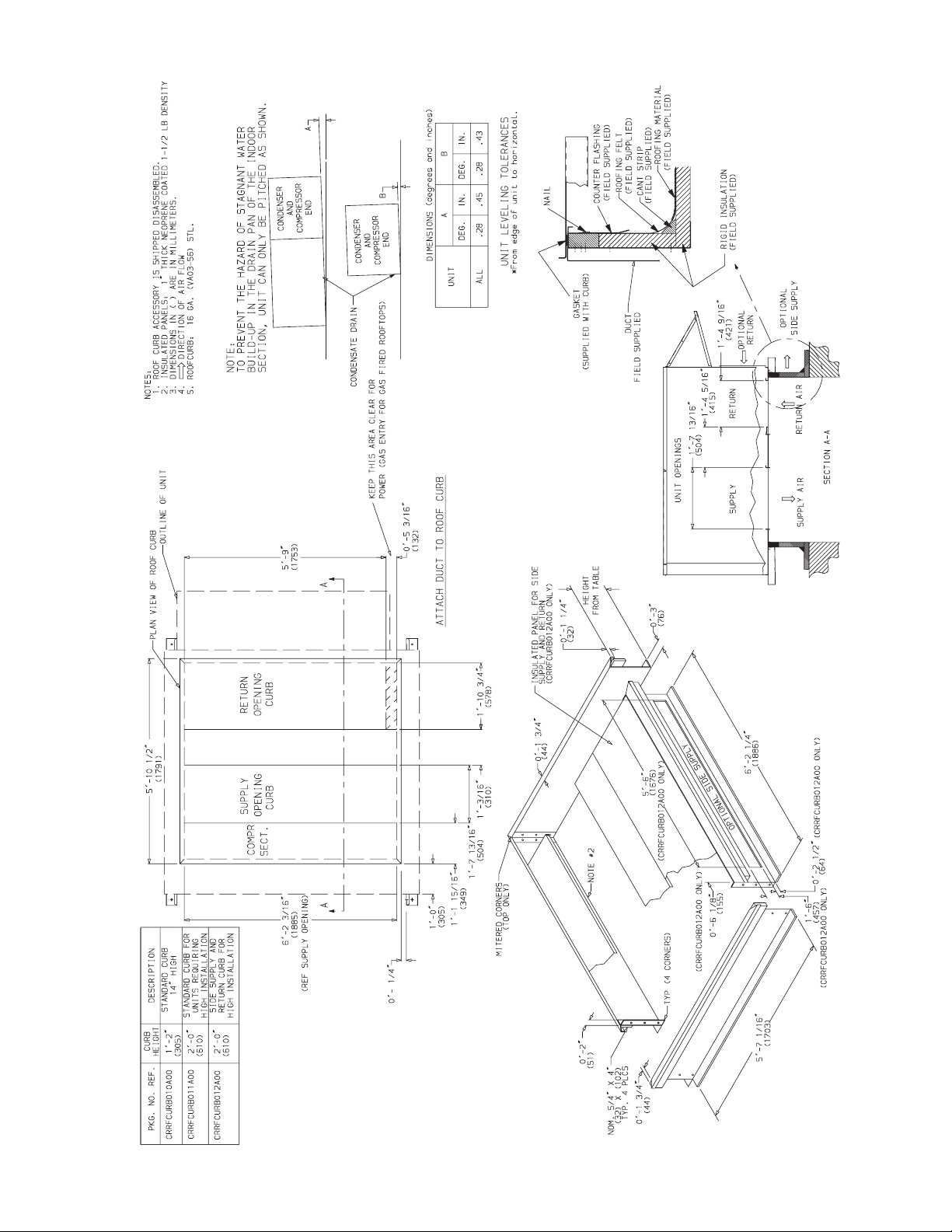
ROOF CURB — Assemble and install accessory roof curb or
horizontal adapter roof curb in accordance with instructions
shipped with this accessory. See Fig. 1-2B. Install insulation,
cant strips, roofing, and counter flashing as shown. Ductwork
can be installed to roof curb or horizontal adapter roof curb be-
fore unit is set in place. Curb or adapter roof curb should be
level. This is necessary to permit unit drain to function proper-
ly. Unit leveling tolerance is ±
1
/
16
in. per linear ft in any direc-
tion. Refer to Accessory Roof Curb or Horizontal Adapter
Roof Curb Installation Instructions for additional information
as required. When accessory roof curb or horizontal adapter
roof curb is used, unit may be installed on class A, B, or C roof
covering material.
ALTERNATE UNIT SUPPORT — When the curb or adapter
cannot be used, install unit on a noncombustible surface. Sup-
port unit with sleepers, using unit curb support area. If sleepers
cannot be used, support long sides of unit with a minimum of
3 equally spaced 4-in. x 4-in. pads on each side.
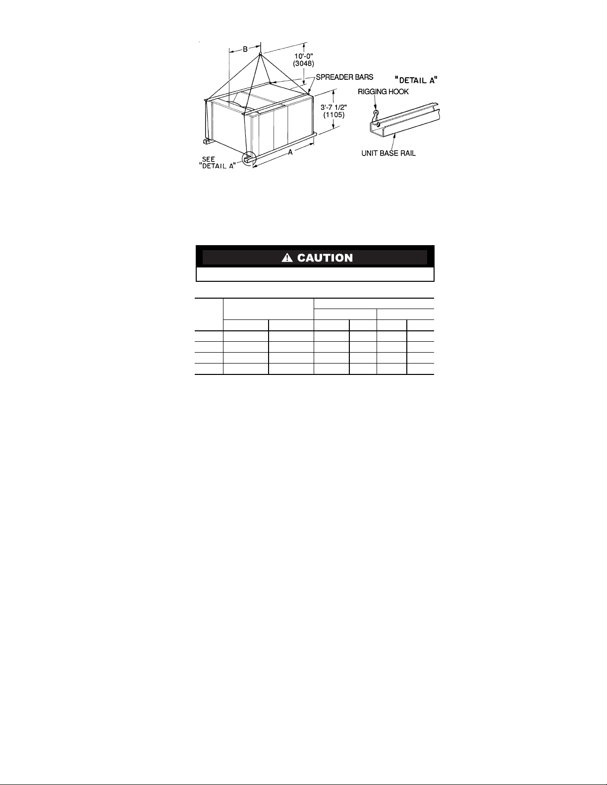
Step 2 — Rig and Place Unit — Do not drop unit;
keep upright. Use spreader bars over unit to prevent sling or ca-
ble damage. Rollers may be used to move unit across a roof.
Level by using unit frame as a reference; leveling tolerance is ±
1
/
16
in. per linear ft in any direction. See Fig. 3 for additional in-
formation. Unit operating weight is shown in Table 1.
Four lifting holes are provided in ends of unit base rails as
shown in Fig. 3. Refer to rigging instructions on unit.
NOTE: On 48TM028 units, the lower forklift braces must
be removed prior to setting unit on roof curb.
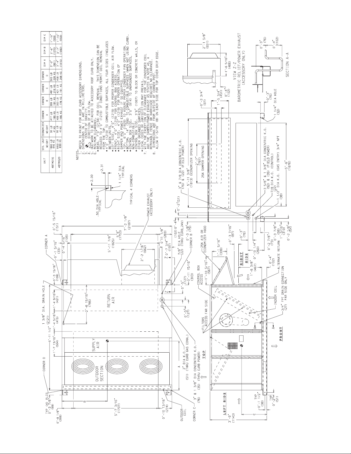
POSITIONING — Maintain clearance, per Fig. 4-6, around
and above unit to provide minimum distance from combustible
materials, proper airflow, and service access.
Do not install unit in an indoor location. Do not locate unit
air inlets near exhaust vents or other sources of contaminated
air. For proper unit operation, adequate combustion and venti-
lation air must be provided in accordance with Section 5.3 (Air
for Combustion and Ventilation) of the National Fuel Gas
Code, ANSI Z223.1 (American National Standards Institute).
Although unit is weatherproof, guard against water from
higher level runoff and overhangs.
Locate mechanical draft system flue assembly at least 4 ft
from any opening through which combustion products could
enter the building, and at least 4 ft from any adjacent building.
When unit is located adjacent to public walkways, flue assem-
bly must be at least 7 ft above grade. Locate unit at least 10 ft
away from adjacent units.
ROOF MOUNT — Check building codes for weight distri-
bution requirements. Unit operating weight is shown in
Table 1.
Instructions continued on page 11.
IMPORTANT: The gasketing of the unit to the roof curb
or adapter roof curb is critical for a watertight seal.
Install gasket with the roof curb or adapter as shown in
Fig. 2A and 2B. Improperly applied gasket can also
result in air leaks and poor unit performance.
Fig. 1 — Horizontal Supply/Return Adapter Installation (48TM016-025)
NOTE: CRRFCURB013A00 is a fully factory preassembled hori-
zontal adapter and includes an insulated transition duct. The pres-
sure drop through the adapter curb is negligible.
For horizontal return applications: The power exhaust and baro-
metric relief dampers must be installed in the return air duct.
23"
14 3/4"
6"
3 1/2"
FULLY INSULATED
SUPPLY PLENUM
1" INSULATION
1 1/2 # DENSITY,
STICK PINNED & GLUED
2" X 1/4
SUPPORT TYP.
STITCH WELDED
12" WIDE STANDING
SEAM PANELS
ACCESSORY
PACKAGE NO.
CURB
HEIGHT
DESCRIPTION
CRRFCURB013A00
1′-11″
(584)
Pre-Assembled, Roof Curb,
Horizontal Adapter
3
Fig. 2A — Roof Curb Details — 48TM016-025

4
Fig. 2B — Roof Curb Details — 48TM028
5
NOTES:
1. Dimensions in ( ) are in millimeters.
2. Refer to Fig. 4-6 for unit operating weights.
3. Remove boards at ends of unit and runners prior to rigging.
4. Rig by inserting hooks into unit base rails as shown. Use corner post from packaging to protect coil from
damage. Use bumper boards for spreader bars on all units.
5. Weights do not include optional economizer. Add 90 lb (41 kg) for economizer weight.
6. Weights given are for aluminum evaporator and condenser coil plate fins.
All panels must be in place when rigging.
Fig. 3 — Rigging Details
UNIT
48TM
MAXIMUM
SHIPPING WEIGHT
DIMENSIONS
AB
lb kg ft-in. mm ft-in. mm
016 1875 850 6-11
1
/
2
2121 4-0 1219
020 1925 873 6-11
1
/
2
2121 3-2 964
025 2035 923 6-11
1
/
2
2121 3-4 1016
028 2445 1109 6-11
1
/
2
2121 3-4 1016
6
Fig. 4 — Base Unit Dimensions — 48TM016,020

7
Fig. 5 — Base Unit Dimensions — 48TM025

8
Fig. 6 — Base Unit Dimensions — 48TM028

9
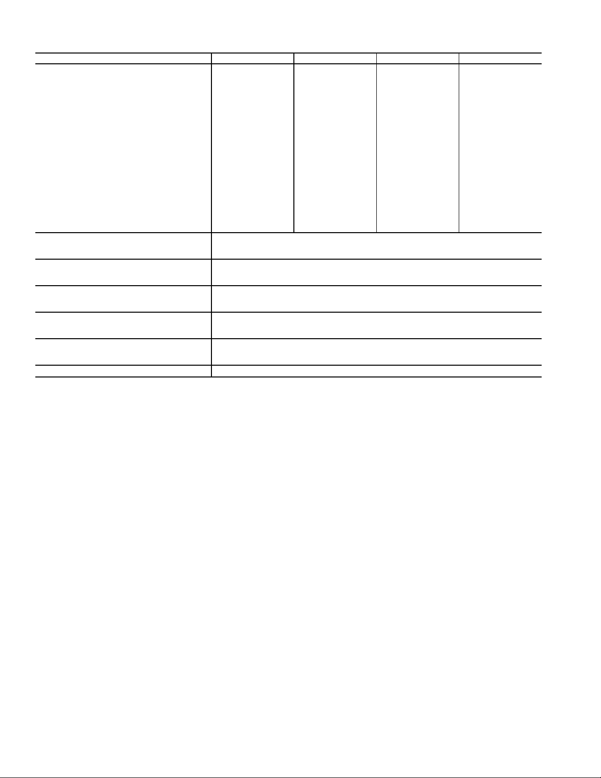
Table 1 — Physical Data
LEGEND
*The ZRU140KC compressor is a tandem compressor, consisting of a ZR72KC (25% total
capacity) and a ZR68KC (24% total capacity).
†Circuit 1 uses the lower portion of the condenser coil and lower portion of the evaporator
coils; and Circuit 2 uses the upper portion of both coils.
**Pulley has 6 turns. Due to belt and pulley size, movable pulley cannot be set to 0 to 1
1
/
2
turns open.
††Pulley has 6 turns. Due to belt and pulley size, movable pulley cannot be set to 0 to
1
/
2
turns
open.
***Rollout switch is manual reset.
†††A Liquid Propane kit is available as an accessory.
¶The 48TM028 unit requires 2-in. industrial-grade filters capable of handling face velocities up
to 625 ft/min (such as American Air Filter no. 5700 or equivalent).
NOTE: The 48TM016-028 units have a low-pressure switch (standard) located on the suction
side.
UNIT 48TM 016D/F 020D/F 025D/F 028D/F
NOMINAL CAPACITY (tons) 15 18 20 25
OPERATING WEIGHT 1800 1850 1900 2270
Economizer 90 90 90 90
MoistureMi$er™ Dehumidification Package 40 40 40 40
COMPRESSOR/MANUFACTURER Scroll, Copeland
Quantity...Model (Ckt 1, Ckt 2)
1...ZR94KC,
1...ZR72KC
1...ZR108KC,
1...ZR94KC
1...ZR125KC,
1...ZR108KC
1...ZRU140KC,*
1...ZR144KC
Capacity Stages (%) 60, 40 55, 45 55, 45 50, 50
Number of Refrigerant Circuits 22 2 2
Oil (oz) (Ckt 1, Ckt 2) 85, 60 106, 81 106,106 136, 106
REFRIGERANT TYPE R-22
Expansion Device TXV
Operating Charge (lb-oz)
Circuit 1† 19-8 19-8 19-11 26-13
Circuit 2 13-8 19-2 13-14 25-10
CONDENSER COIL Cross-Hatched
3
/
8
-in. Copper Tubes, Aluminum Lanced,
Aluminum Pre-Coated, or Copper Plate Fins
Rows...Fins/in. 4...15 4...15 4...15 3...15 (2 coils)
Total Face Area (sq ft) 21.7 21.7 21.7 43.4
CONDENSER FAN Propeller Type
Nominal Cfm 10,500 10,500 14,200 21,000
Quantity...Diameter (in.) 3...22 3...22 2...30 6...22
Motor Hp...Rpm
1
/
2
...1050
1
/
2
...1050 1...1075
1
/
2
...1050
Watts Input (Total) 1100 1100 3400 2200
EVAPORATOR COIL Cross-Hatched
3
/
8
-in. Copper Tubes, Aluminum Lanced or
Copper Plate Fins, Face Split
Rows...Fins/in. 4...15 4...15 4...15 4...15
Total Face Area (sq ft) 17.5 17.5 17.5 17.5
EVAPORATOR FAN Centrifugal Type
Quantity...Size (in.) 2...12 x 12 2...12 x 12 2...12 x 12 2...12 x 12
Type Drive Belt Belt Belt Belt
Nominal Cfm 6000 7200 8000 10,000
Motor Hp 55 7.5 10
Motor Nominal Rpm 1745 1745 1745 1740
Maximum Continuous Bhp 6.13 5.90
8.7 [208/230, 575 v]
9.5 [460 v]
10.2 [208/230, 575 v]
11.8 [460 v]
Motor Frame Size 184T 184T 213T 215T
Nominal Rpm High/Low —— — —
Fan Rpm Range Low-Medium Static 873-1021 910-1095 1002-1151 1066-1283
High Static 1025-1200 1069-1287 1193-1369 1332-1550
Motor Bearing Type Ball Ball Ball Ball
Maximum Allowable Rpm 1550 1550 1550 1550
Motor Pulley Pitch Diameter Low-Medium Static 4.9/5.9 4.9/5.9 5.4/6.6 4.9/5.9
Min/Max (in.) High Static 4.9/5.9 4.9/5.9 5.4/6.6 4.9/5.9
Nominal Motor Shaft Diameter (in.) 1
1
/
8
1
1
/
8
1
3
/
8
1
3
/
8
Fan Pulley Pitch Diameter (in.) Low-Medium Static 9.4 9.4 9.4 8.0
High Static 8.0 8.0 7.9 6.4
Nominal Fan Shaft Diameter (in.) 1
7
/
16
1
7
/
16
1
7
/
16
1
7
/
16
Belt, Quantity...Type...Length (in.) Low-Medium Static 1...BX...50 1...BX...50 1...BX...53 2...BX...50
High Static 1...BX...48 1...BX...48 1...BX...50 2...BX...47
Pulley Center Line Distance (in.) 13.3-14.8 13.3-14.8 14.6-15.4 14.6-15.4
Speed Change per Full Turn of
Movable Pulley Flange (rpm)
Low-Medium Static 37 37 37 36
High Static 44 34 44 45
Movable Pulley Maximum Full Turns
From Closed Position 6** 6†† 6** 6††
Factory Speed 3.5 3.5 3.5 3.5
Factory Speed Setting (rpm) Low-Medium Static 965 1002 1120 1182
High Static 1134 1178 1328 1470
Fan Shaft Diameter at Pulley (in.) 1
7
/
16
1
7
/
16
1
7
/
16
1
7
/
16
Bhp — Brake Horsepower
TXV — Thermostatic Expansion Valve
10
Table 1 — Physical Data (cont)
LEGEND
*The ZRU140KC compressor is a tandem compressor, consisting of a ZR72KC (25% total
capacity) and a ZR68KC (24% total capacity).
†Circuit 1 uses the lower portion of the condenser coil and lower portion of the evaporator
coils; and Circuit 2 uses the upper portion of both coils.
**Pulley has 6 turns. Due to belt and pulley size, movable pulley cannot be set to 0 to 1
1
/
2
turns open.
††Pulley has 6 turns. Due to belt and pulley size, movable pulley cannot be set to 0 to
1
/
2
turns
open.
***Rollout switch is manual reset.
†††A Liquid Propane kit is available as an accessory.
¶The 48TM028 unit requires 2-in. industrial-grade filters capable of handling face velocities up
to 625 ft/min (such as American Air Filter no. 5700 or equivalent).
NOTE: The 48TM016-028 units have a low-pressure switch (standard) located on the suction
side.
UNIT 48TM 016D/F 020D/F 025D/F 028D/F
FURNACE SECTION
Rollout Switch Cutout Temp (F)*** 190 190 190 190
Burner Orifice Diameter (in. ...drill size)
Natural Gas Std 0.1285...30/0.136...29 0.1285...30/0.136...29 0.1285...30/0.136...29 0.1285...30/0.136...29
Thermostat Heat Anticipator Setting (amps)
208/230, 575 v Stage 1 0.98 0.98 0.98 0.98
Stage 2 0.44 0.44 0.44 0.44
460 v Stage 1 0.80 0.80 0.80 0.80
Stage 2 0.44 0.44 0.44 0.44
Gas Input Stage 1 172,000/225,000 206,000/270,000 206,000/270,000 206,000/270,000
Stage 2 230,000/300,000 275,000/360,000 275,000/360,000 275,000/360,000
Efficiency (Steady-State) (%) 81 81 81 81
Temperature Rise Range 15-45/20-50 15-45/20-50 15-45/20-50 15-45/20-50
Manifold Pressure (in. wg)
Natural Gas Std 3.3 3.3 3.3 3.3
Liquid Propane††† Alt 3.3 3.3 3.3 3.3
Gas Valve Quantity 1111
Gas Valve Pressure Range
in. wg 5.5-13.5 5.5-13.5 5.5-13.5 5.5-13.5
psig 0.235-0.487 0.235-0.487 0.235-0.487 0.235-0.487
Field Gas Connection Size (in.-FPT)
3
/
4
3
/
4
3
/
4
3
/
4
HIGH-PRESSURE SWITCH (psig)
Cutout 426
Reset (Auto) 320
LOW-PRESSURE SWITCH (psig)
Cutout 27
Reset (Auto) 44
FREEZE PROTECTION THERMOSTAT (F)
Opens 30 ± 5
Closes 45 ± 5
OUTDOOR-AIR INLET SCREENS Cleanable
Quantity...Size (in.) 2...20 x 25 x 1
1...20 x 20 x 1
RETURN-AIR FILTERS Throwaway¶
Quantity...Size (in.) 4...20 x 20 x 2
4...16 x20 x 2
POWER EXHAUST
1
/
2
Hp, 208/230-460 v Motor Direct Drive, Propeller-Fan (Factory-Wired for 460 v)
Bhp — Brake Horsepower
TXV — Thermostatic Expansion Valve

11
Step 3 — Field Fabricate Ductwork — Secure all
ducts to building structure. Use flexible duct connectors be-
tween unit and ducts as required. Insulate and weatherproof all
external ductwork, joints, and roof openings with counter
flashing and mastic in accordance with applicable codes.
Ducts passing through an unconditioned space must be in-
sulated and covered with a vapor barrier.
Step 4 — Make Unit Duct Connections — Unit
is shipped for thru-the-bottom duct connections. Ductwork
openings are shown in Fig. 1 and 4-6. Duct connections are
shown in Fig. 7. Field-fabricated concentric ductwork may be
connected as shown in Fig. 8 and 9. Attach all ductwork to roof
curb and roof curb basepans.
Step 5 — Install Flue Hood and Wind Baffle —
Flue hood and wind baffle are shipped secured under main
control box. To install, secure flue hood to access panel. See
Fig. 10. The wind baffle is then installed over the flue hood.
NOTE: When properly installed, flue hood will line up with
combustion fan housing. See Fig. 11.
Step 6 — Trap Condensate Drain — See Fig. 12
for drain location. One
3
/
4
-in. half coupling is provided inside
unit evaporator section for condensate drain connection. An
8
1
/
2
-in. x
3
/
4
-in. diameter and 2-in. x
3
/
4
-in. diameter pipe nip-
ple, coupled to standard
3
/
4
-in. diameter elbows, provide a
straight path down through hole in unit base rails (see Fig. 13).
A trap at least 4-in. deep must be used.
WIND
BAFFLE
NOTE: Dimensions A, A′, B, and B′ are obtained from field-supplied
ceiling diffuser.
Shaded area indicates block-off panels.
Fig. 9 — Concentric Duct Details
Fig. 10 — Flue Hood Location
NOTE: Do not drill in this area; damage to basepan may result in
water leak.
Fig. 8 — Concentric Duct Air Distribution
NOTE: Do not drill in this area; damage to basepan may result in
water leak.
Fig. 7 — Air Distribution — Thru-the-Bottom

12
Step 7 — Orifice Change — This unit is factory as-
sembled for heating operation using natural gas at an elevation
from sea level to 2000 ft. This unit uses orifice type
LH32RFnnn, where “nnn” indicates the orifice size based on
drill size diameter in thousands of an inch.
HIGH ELEVATION (Above 2000 ft) — Use accessory high
altitude kit when installing this unit at an elevation of 2000 to
7000 ft. For elevations above 7000 ft, refer to Table 2 to identi-
fy the correct orifice size for the elevation. See Table 3 for the
number of orifices required for each unit size. Purchase these
orifices from your local Carrier dealer. Follow instructions in
accessory Installation Instructions to install the correct orifices.
Table 2 — Altitude Compensation*
*As the height above sea level increases, there is less oxygen per
cubic foot of air. Therefore, heat input rate should be reduced at
higher altitudes. Includes a 4% input reduction per each 1000 ft.
†Orifices available through your Carrier dealer.
Table 3 — Orifice Quantity
CONVERSION TO LP (Liquid Propane) GAS — Use acces-
sory LP gas conversion kit when converting this unit for use
with LP fuel usage for elevations up to 7000 ft. For elevations
above 7000 ft, refer to Table 4 to identify the correct orifice
size for the elevation. See Table 3 for the number of orifices
required for each unit size. Purchase these orifices from your
local Carrier dealer. Follow instructions in accessory Installa-
tion Instructions to install the correct orifices.
Table 4 — LP Gas Conversion*
*As the height above sea level increases, there is less oxygen per
cubic foot of air. Therefore, heat input rate should be reduced at
higher altitudes. Includes a 4% input reduction per each 1000 ft.
†Orifices available through your Carrier dealer.
ELEVATION (ft)
NATURAL GAS ORIFICE†
Low Heat High Heat
0-1,999 30 29
2,000 30 29
3,000 31 30
4,000 31 30
5,000 31 30
6,000 31 30
7,000 32 31
8,000 32 31
9,000 33 31
10,000 35 32
UNIT ORIFICE QUANTITY
48TMD016 5
48TMD020,
48TMD024,
48TMD028,
48TMF016
6
48TMF020,
48TMF024,
48TMF028
7
ELEVATION (ft) LP GAS ORIFICE†
0-1,999 36
2,000 37
3,000 38
4,000 38
5,000 39
6,000 40
7,000 41
8,000 41
9,000 42
10,000 43
INDUCED DRAFT
MOTOR
MAIN BURNER
SECTION
COMBUSTION
FAN HOUSING
HEAT EXCHANGER
SECTION
Fig. 11 — Combustion Fan Housing Location
3/4" FPT DRAIN
CONNECTION
1-3/8"
DRAIN HOLE
Fig. 12 — Condensate Drain Details
(48TM016 Shown)
Fig. 13 — Condensate Drain Piping Details
13
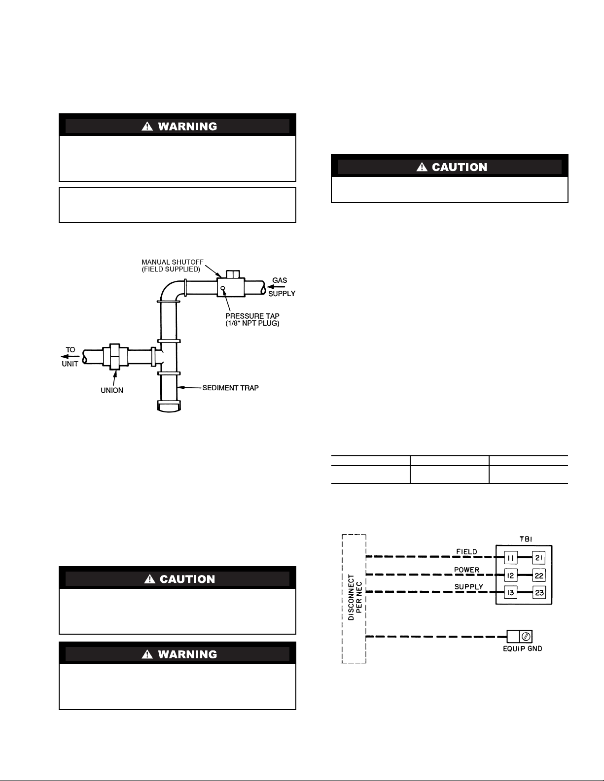
Step 8 — Install Gas Piping — Unit is equipped for
use with natural gas. Installation must conform with local
building codes or, in the absence of local codes, with the
National Fuel Gas Code, ANSI Z223.1.
Install field-supplied manual gas shutoff valve with a
1
/
8
-in.
NPT pressure tap for test gage connection at unit. Field gas
piping must include sediment trap and union. See Fig. 14.
Size gas-supply piping for 0.5-in. wg maximum pressure
drop. Do not use supply pipe smaller than unit gas connection.
Step 9 — Make Electrical Connections
FIELD POWER SUPPLY — Unit is factory wired for volt-
ageshownonnameplate.
When installing units, provide a disconnect per NEC
(National Electrical Code) of adequate size (Table 5).
All field wiring must comply with NEC and local
requirements.
Route power ground lines through control box end panel or
unit basepan (see Fig. 4-6) to connections as shown on unit
wiring diagram and Fig. 15.
Field wiring must confirm to temperature limitations for
type “T” wire. All field wiring must comply with NEC and lo-
cal requirements.
Transformer no. 1 is wired for 230-v unit. If 208/230-v unit
is to be run with 208-v power supply, the transformer must be
rewired as follows:
1. Remove cap from red (208 v) wire.
2. Remove cap from orange (230 v) spliced wire.
3. Replace orange wire with red wire.
4. Recap both wires.
Operating voltage to compressor must be within voltage
range indicated on unit nameplate. On 3-phase units, voltages
between phases must be balanced within 2%.
Unit failure as a result of operation on improper line voltage
or excessive phase imbalance constitutes abuse and may cause
damage to electrical components.
FIELD CONTROL WIRING — Install a Carrier-approved
accessory thermostat assembly according to installation in-
structions included with accessory. Locate thermostat assembly
on a solid interior wall in the conditioned space to sense aver-
age temperature.
Route thermostat cable or equivalent single leads of
colored wire from subbase terminals through conduit in unit to
low-voltage connections as shown on unit label wiring diagram
andinFig.16.
NOTE: For wire runs up to 50 ft, use no. 18 AWG (American
Wire Gage) insulated wire (35 C minimum). For 50 to 75 ft,
use no. 16 AWG insulated wire (35 C minimum). For over
75 ft, use no. 14 AWG insulated wire (35 C minimum). All
wire larger than no. 18 AWG cannot be directly connected at
the thermostat and will require a junction box and splice at the
thermostat.
Set heat anticipator settings as follows:
Settings may be changed slightly to provide a greater degree
of comfort for a particular installation.
Do not pressure test gas supply while connected to unit.
Always disconnect union before servicing. Exceeding
maximum manifold pressure may cause explosion and
injury.
IMPORTANT: Natural gas pressure at unit gas connec-
tion must not be less than 5.5 in. wg or greater than
13.5 in. wg.
The correct power phasing is critical in the operation of the
scroll compressors. An incorrect phasing will cause the
compressor to rotate in the wrong direction. This may lead
to premature compressor failure.
The unit must be electrically grounded in accordance with
local codes and NEC ANSI/NFPA 70 (National Fire Pro-
tection Association) to protect against fire and electrical
shock.
Be certain unused wires are capped. Failure to do so may
damage the transformers.
VO LTAGE W1 W 2
208/230,575
460
0.98
0.80
0.44
0.44
NOTE:ThemaximumwiresizeforTB1is2/0.
LEGEND
Fig. 15 — Field Power Wiring Connections
EQUIP — Equipment
GND — Ground
NEC — National Electrical Code
TB — Terminal Block
Fig. 14 — Field Gas Piping
14
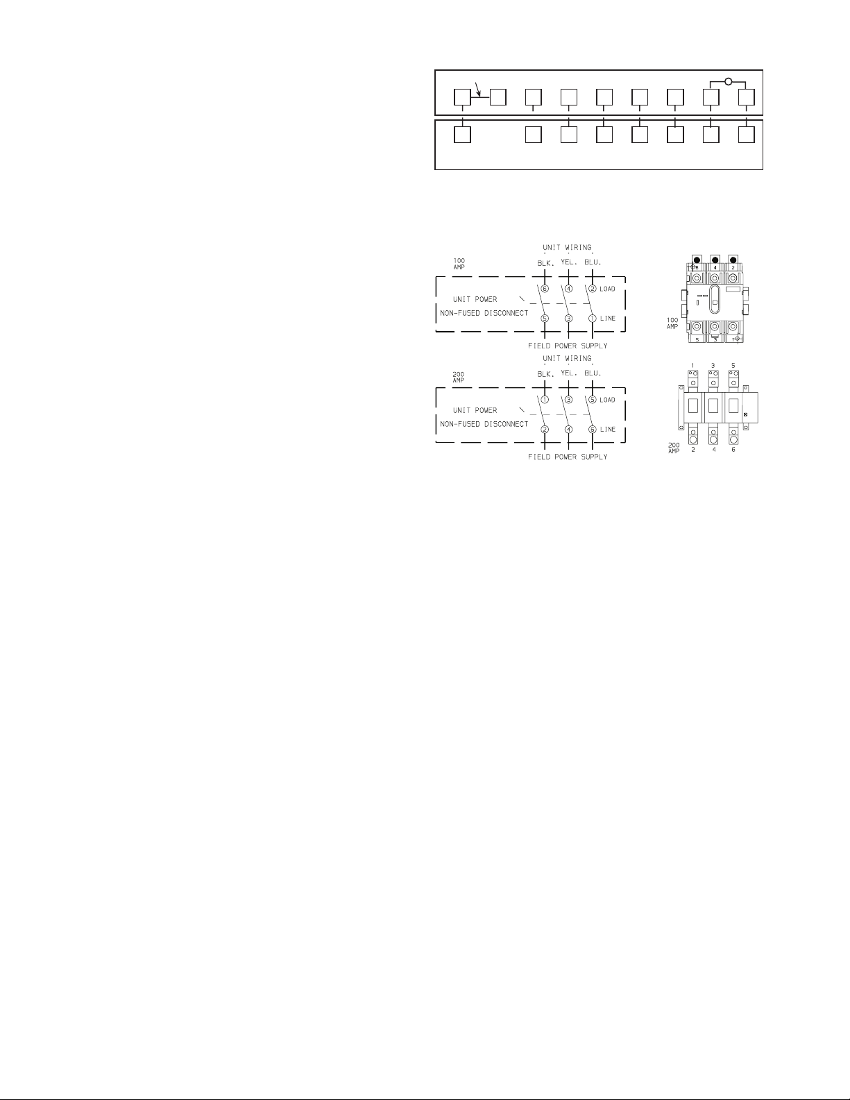
OPTIONAL NON-FUSED DISCONNECT — On units with
the optional non-fused disconnect, incoming power will be
wired into the disconnect switch. Refer to Fig. 17 for wiring
for 100 and 200 amp disconnect switches. Units with an
MOCP (maximum overcurrent protection) under 100 will use
the 100 amp disconnect switch. Units with an MOCP over 100
will use the 200 amp disconnect switch. Refer to the applicable
disconnect wiring diagram.
To prevent breakage during shipping, the disconnect han-
dle and shaft are shipped and packaged inside the unit control
box. Install the disconnect handle before unit operation. To in-
stall the handle and shaft, perform the following procedure:
1. Open the control box door and remove the handle and
shaft from shipping location.
2. Loosen the Allen bolt located on the disconnect switch.
The bolt is located on the square hole and is used to hold
the shaft in place. The shaft cannot be inserted until the
Allen bolt is moved.
3. Insert the disconnect shaft into the square hole on the dis-
connect switch. The end of the shaft is specially cut and
the shaft can only be inserted in the correct orientation.
4. Tighten the Allen bolt to lock the shaft into position.
5. Close the control box door.
6. Attach the handle to the external access door with the two
screws provided. When the handle is in the ON position,
thehandlewillbevertical.WhenthehandleisintheOFF
position, the handle will be horizontal.
7. Turn the handle to the OFF position and close the door.
The handle should fit over the end of the shaft when the
door is closed.
8. The handle must be in the OFF position to open the con-
trol box door.
OPTIONAL CONVENIENCE OUTLET — On units with
optional convenience outlet, a 115-v GFI (ground fault inter-
rupt) convenience outlet receptacle is provided for field wiring.
Field wiring should be run through the
7
/
8
-in. knockout pro-
vided in the basepan near the return air opening.
RH
RC
Y1 Y2
W1
W2
GC
X
L
X
C
G
W2
W1Y2
Y1
R
REMOVABLE JUMPER
RED
BLU
PNK
ORN
VIO
BLK
BRN
WHT
THERMOSTAT ASSEMBLY
5L3 3L2 1L1 LINE
6T3 4T2 2T1 LOAD
Fig. 16 — Field Control Thermostat Wiring
NOTE: The disconnect takes the place of TB-1 as shown on the unit wiring dia
-
gram label and the component arrangement label.
Fig. 17 — Optional Non-Fused Disconnect Wiring

15
Table 5 — Electrical Data
LEGEND
*Fuse or HACR circuit breaker.
NOTES:
1. In compliance with NEC requirements for multimotor and combination
load equipment (refer to NEC Articles 430 and 440), the overcurrent pro-
tective device for the unit shall be fuse or HACR breaker. Canadian units
maybefuseorcircuitbreaker.
2. Unbalanced 3-Phase Supply Voltage
Never operate a motor where a phase imbalance in supply voltage is
greater than 2%.
Use the following formula to determine the percent
voltage imbalance.
% Voltage Imbalance
EXAMPLE: Supply voltage is 460-3-60.
Determine maximum deviation from average voltage.
(AB) 457 – 452 = 5v
(BC) 464 – 457 = 7v
(AC) 457 – 455 = 2v
Maximum deviation is 7 v.
Determine percent voltage imbalance.
= 1.53%
This amount of phase imbalance is satisfactory as it is below the maximum
allowable 2%.
UNIT
48TM
NOMINAL
VOLTAGE
(3 Ph, 60 Hz)
VO LTAG E
RANGE
COMPRESSOR
OFM IFM
POWER
EXHAUST
COMBUSTION
FAN M OTO R
POWER
SUPPLY
No. 1 No. 1A No. 2
Min Max RLA LRA RLA LRA RLA LRA Qty Hp FLA (ea) Hp FLA FLA LRA FLA MCA MOCP*
016
208/230 187 253 32.1 195 — — 20.7 156 3 0.5 1.7 5.0 15.8/15.8
— — 0.57 82/82 110/110
4.6 18.8 0.57 86/86 110/110
460 414 508 16.4 95 — — 10 70 3 0.5 0.8 5.0 7.9
— — 0.30 41 50
2.3 6.0 0.30 43 50
575 518 633 12 80 — — 8.2 54 3 0.5 0.75 5.0 6.0
— — 0.57 31 40
2.1 4.8 0.57 34 40
020
208/230 187 253 30.1 225 — — 28.8 195 3 0.5 1.7 5.0 15.8/15.8
— — 0.57 87/87 110/110
4.6 18.8 0.57 92/92 110/110
460 414 508 15.5 114 — — 14.7 95 3 0.5 0.8 5.0 7.9
— — 0.30 44 50
2.3 6.0 0.30 47 60
575 518 632.5 12.1 80 — — 10.7 80 3 0.5 0.75 5.0 6.0
— — 0.57 34 40
2.1 4.8 0.57 36 40
025
208/230 187 253 42 239 — — 33.6 225 2 1 6.6 7.5 25.0/25.0
— — 0.57 124/124 150/150
4.6 18.8 0.57 129/129 150/150
460 414 508 19.2 125 — — 17.3 114 2 1 3.3 7.5 13.0
— — 0.30 61 80
2.3 6.0 0.30 63 80
575 518 633 13.8 80.0 — — 13.5 80.0 2 1.0 3.4 7.5 10.0
— — 0.57 48 60
2.1 4.8 0.57 50 60
028
208/230 187.2 253 20.7 156 20.7 156 47.1 245 6 0.5 1.7 10.0 28.0/28.0
— — 0.57 138/138 175/175
4.6 18.8 0.57 143/143 150/175
460 414 508 10 75 10 75 19.6 125 6 0.5 0.8 10.0 14.6
— — 0.30 64 80
2.3 6 0.30 66 80
575 517.5 632.5 8.2 54 8.2 54 15.8 100 6 0.5 0.8 10.0 13.0
— — 0.57 54 60
2.1 4.8 0.57 56 70
FLA — Full Load Amps
HACR — Heating, Air Conditioning and Refrigeration
IFM — Indoor (Evaporator) Fan Motor
LRA — Locked Rotor Amps
MCA — Minimum Circuit Amps
MOCP — Maximum Overcurrent Protection
NEC — National Electrical Code
OFM — Outdoor (Condenser) Fan Motor
RLA — RatedLoadAmps
= 100 x
max voltage deviation from average voltage
average voltage
AB = 452 v
BC = 464 v
AC = 455 v
Average Voltage =
452 + 464 + 455
3
=
1371
3
= 457
% Voltage Imbalance = 100 x
7
457
IMPORTANT: If the supply voltage phase imbalance is more than 2%,
contact your local electric utility company immediately.
16
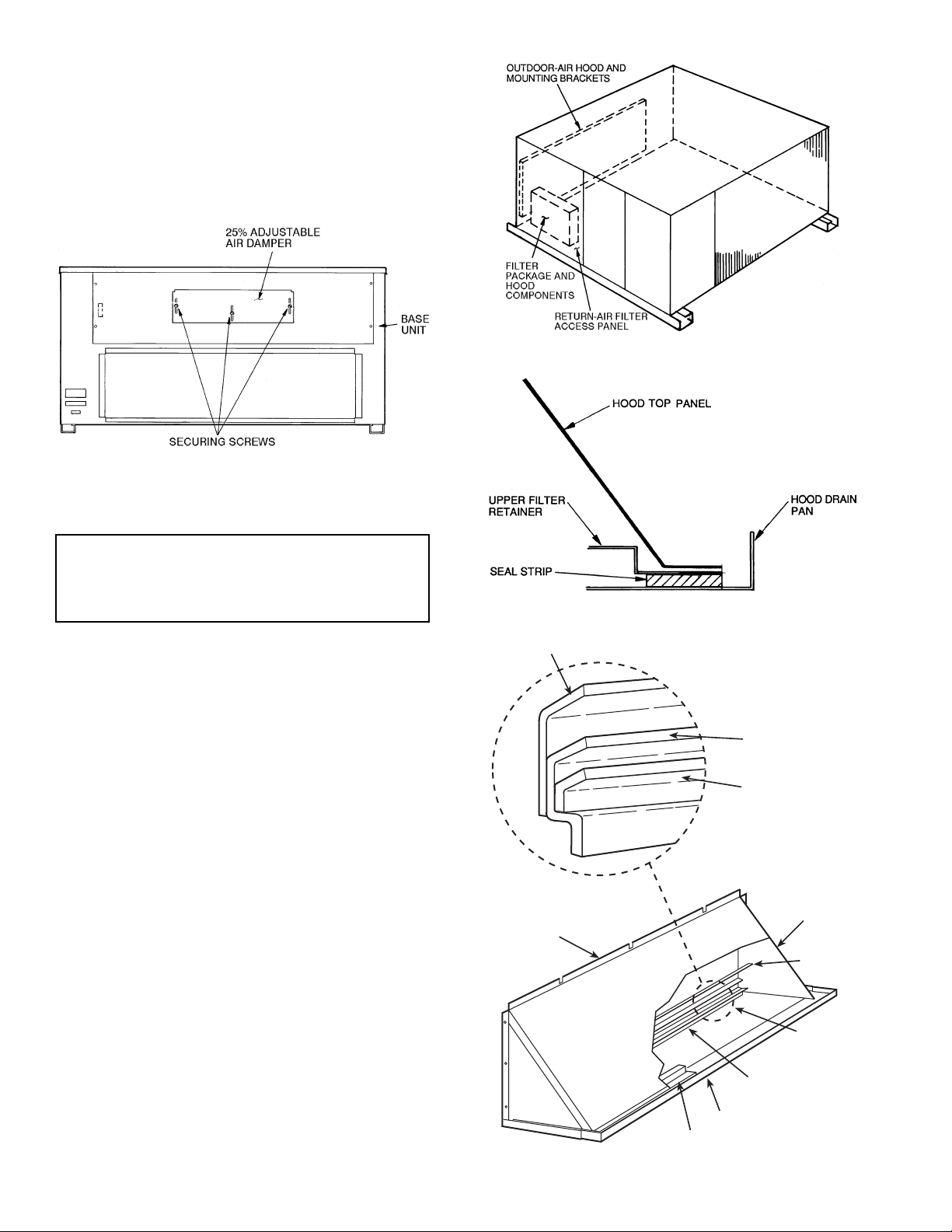
Step 10 — Make Outdoor-Air Inlet Adjust-
ments
MANUAL OUTDOOR-AIR DAMPER — All units (except
those equipped with a factory-installed economizer) have a
manual outdoor-air damper to provide ventilation air.
Damper can be preset to admit up to 25% outdoor air into
return-air compartment. To adjust, loosen securing screws and
move damper to desired setting, then retighten screws to secure
damper (Fig. 18).
Step 11 — Install Outdoor-Air Hood
The outdoor-air hood is common to 25% air ventilation,
EconoMi$erIV and EconoMi$er2. If EconoMi$erIV or
EconoMi$er2 is used, all electrical connections have been
made and adjusted at the factory. Assemble and install hood in
the field.
NOTE: The hood top panel, upper and lower filter retainers,
hood drain pan, baffle (sizes 025 and 028), and filter support
bracket are secured opposite the condenser end of the unit. The
screens, hood side panels, remaining section of filter support
bracket, seal strip, and hardware are in a package located
inside the return-air filter access panel (Fig. 19).
1. Attach seal strip to upper filter retainer. See Fig. 20.
2. Assemble hood top panel, side panels, upper filter retain-
er, and drain pan (see Fig. 21).
3. Secure lower filter retainer and support bracket to unit.
See Fig. 21. Leave screws loose on 025 and 028 units.
4. Slide baffle (sizes 025 and 028) behind lower filter retain-
er and tighten screws.
5. Loosen sheet metal screws for top panel of base unit
located above outdoor-air inlet opening, and remove
screws for hood side panels located on the sides of the
outdoor-air inlet opening.
6. Match notches in hood top panel to unit top panel screws.
Insert hood flange between top panel flange and unit.
Tighten screws.
7. Hold hood side panel flanges flat against unit, and install
screwsremovedinStep5.
8. Insert outdoor-air inlet screens and spacer in channel
created by lower filter retainer and filter support bracket.
IMPORTANT: If the unit is equipped with the optional
EconoMi$erIV component, move the outdoor-air tempera-
ture sensor prior to installing the outdoor-air hood. See the
Optional EconoMi$erIV and EconoMi$er2 section for
more information.
Fig. 18 — Standard 25% Outdoor-Air
Section Details
Fig. 19 — Outdoor-Air Hood Component Location
Fig. 20 — Seal Strip Location
HOOD TOP
PANEL
HOOD SIDE
PANELS (2)
BAFFLE
(025 AND
028 ONLY)
LOWER
FILTER
RETAINER
FILTER SUPPORT
BRACKET
HOOD DRAIN PAN
UPPER FILTER RETAINER
BAFFLE
LOWER FILTER
RETAINER
FILTER SUPPORT
BRACKET
Fig. 21 — Outdoor-Air Hood Details

17
Step 12 — Install All Accessories — After all the
factory-installed options have been adjusted, install all field-
installed accessories. Refer to the accessory installation
instructions included with each accessory.
MOTORMASTER® I CONTROL INSTALLATION
(48TM016,020, and 028)
Install Field-Fabricated Wind Baffles
— Wind baffles must
be field-fabricated for all units to ensure proper cooling cycle
operation at low ambient temperatures. See Fig. 22 for baffle
details. Use 20-gage, galvanized sheet metal, or similar
corrosion-resistant metal for baffles. Use field-supplied screws
to attach baffles to unit. Screws should be
1
/
4
-in. diameter and
5
/
8
-in. long. Drill required screw holes for mounting baffles.
Install Motormaster I Controls — Only one Motormaster I
control is required for 48TM016 and 020 units. The 48TM028
requires 2 Motormaster I controls — one for circuit 1 and
one for circuit 2. The Motormaster I control must be used in
conjunction with the accessory 0° F low ambient kit
(purchased separately). The Motormaster I device controls
outdoor fan no. 1 (and 4 on size 028 units) while outdoor fans
no. 2 and 3 (and 5 and 6 on 028 units) are sequenced off by the
Accessory 0° F Low Ambient Kit.
Accessory 0° F Low Ambient Kit — Install the accessory 0° F
low ambient kit per instruction supplied with accessory.
Sensor Assembly — Install the sensor assembly in the location
shown in Fig. 23.
Motor Mount — To ensure proper fan height, replace the exist-
ing motor mount with the new motor mount provided with
accessory.
Transformer (460 and 575-v Units Only) — On 460 and 575-v
units, a transformer is required. The transformer is provided
with the accessory and must be field-installed.
Motormaster I Control — Recommended mounting location is
on the inside of the panel to the left of the control box. The
control should be mounted on the inside of the panel, verti-
cally, with leads protruding from bottom of extrusion.
To avoid damage to the refrigerant coils and electrical com-
ponents, use recommended screw sizes only. Use care
when drilling holes.
NOTE: Dimensions in ( ) are in mm.
Fig. 22 — Wind Baffle Details
SENSOR
LOCATION
HAIRPIN END
SENSOR
LOCATION
HAIRPIN END
SENSOR
LOCATION
HAIRPIN END
48TM016 48TM020 48TM028
(Circuits 1 and 2)
NOTE: All sensors are located on the eighth hairpin up from the
bottom.
Fig. 23 — Motormaster® I Sensor Locations
18
MOTORMASTER® V CONTROL INSTALLATION
(48TM025 Only)
Install Field-Fabricated Wind Baffles
— Wind baffles must
be field-fabricated for all units to ensure proper cooling cycle
operation at low ambient temperatures. See Fig. 22 for baffle
details. Use 20-gage, galvanized sheet metal, or similar
corrosion-resistant metal for baffles. Use field-supplied screws
to attach baffles to unit. Screws should be
1
/
4
-in. diameter and
5
/
8
-in. long. Drill required screw holes for mounting baffles.
Install Motormaster V Controls
— The Motormaster V
(MMV) control is a motor speed control device which adjusts
condenser fan motor speed in response to declining liquid
refrigerant pressure. A properly applied Motormaster V control
extends the operating range of air-conditioning systems and
permits operation at lower outdoor ambient temperatures.
The minimum ambient temperatures at which the unit will
operate are:
To operate down to the ambient temperatures listed,
Motormaster V controls (Fig. 24) must be added. Field-
fabricated and installedwind bafflesare also required for all units
(see Fig. 22). The Motormaster V control permits operation of
the unit to an ambient temperature of –20 F (–29 C). The control
regulates the speed of 3-phase fan motors that are compatible
with the control. These motors are factory installed.
See Table 6 for the Motormaster V control accessory
package usage. Table 7 shows applicable voltages and motors.
Replacement of fan motor IS NOT REQUIRED ON
CURRENT PRODUCTION UNITS since the control is
compatible with the factory-installed fan motors. Only field
wiring control is required.
Install the Motormaster V control per instructions supplied
with accessory.
Table 6 — Motormaster V Control Package Usage
Table 7 — Applicable Voltages and Motors
To avoid damage to the refrigerant coils and electrical com-
ponents, use recommended screw sizes only. Use care
when drilling holes.
TE MP ER ATU RE OP ER ATI NG L IM ITS — F° (C °)
Standard
Unit
Unit with
Low Ambient Kit
Unit with
MMV Control
40 (4) 25 (–4) –20 (–29)
UNIT VOLTAGE ITEM DESCRIPTION
48TM016-028
208/230 CRLOWAMB015A00
460 CRLOWAMB016A00
575 CRLOWAMB017A00
VOLTAGE COMPATIBLE MOTOR
208/230-3-60 HD52AK654
460-3-60 HD52AK654
575-3-60 HD52GE576
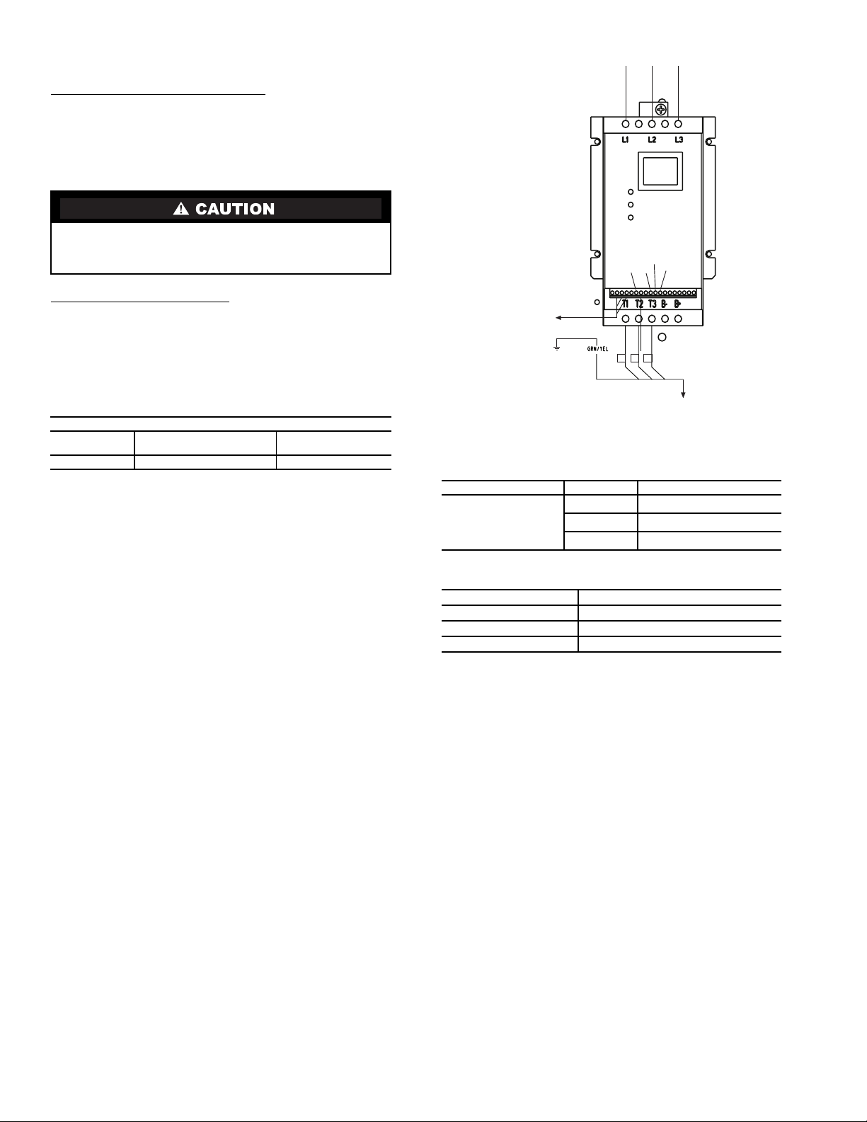
Fig. 24 — Motormaster® V Control
256
2
12 13A
13B
13C
1
2
3
TO MOTOR(S)
TO PRESSURE
TRANSDUCER
BLK
YEL
BLU
FROM FUSE BLOCK
B
 Loading...