


48NLT
Table of contents
 Loading...
48NLT, NMT, NET, NHT AND NVT 018-060
HEATING & COOLING
Packaged Heating/Cooling Units
Installation, Start-Up and Service Instructions
CONTENTS
Page
SAFETY CONSIDERATIONS
General
Job Data ..................................
RECEIVING AND INSTALLATION
Step 1 — Check Equipment
• IDENTIFY MACHINE
• INSPECT SHIPMENT
Step 2 — Provide Unit Support
• ROOF CURB
• SLAB MOUNT
Step 3 — Provide Ciearances .................................4
Step 4 — Rig and Place Unit....................................4
Step 5 — Connect Condensate Drain
Step 6 - instali Venting
Step 7 - Instail Gas Piping
Step 8 — Instail Duct Connections
Step 9 - Instail Electrical Connections
• HIGH VOLTAGE CONNECTIONS
• SPECIAL PROCEDURES FOR 208-V
• CONTROL VOLTAGE CONNECTIONS
• HEAT ANTICIPATOR SETTING
• TRANSFORMER CIRCUIT PROTECTION
PRE-START-UP
START-UP
MAINTENANCE
NOTE TO INSTALLER — Before the installation, READ
THESE INSTRUCTIONS CAREFULLY AND COM
PLETELY. Also, make sure the User’s Manual and Re
placement Guide are left with the unit after installation.
...................................
....................
............................
...............................
.....................
......................................
.................................
.....................
.............
OPERATION
..........
SAFETY CONSIDERATIONS
Installation and servicing of air conditioning equipment
can be hazardous due to system pressure and electrical com
ponents. Only trained and qualified personnel should in
stall, repair or service air conditioning equipment.
Untrained personnel can perform basic maintenance func
tions of cleaning coils and filters. All other operations should
be performed by trained service personnel. When working
on air conditioning equipment, observe precautions in the
literature, tags and labels attached to the unit and other safety
precautions that may apply.
Follow all safety codes. Wear safety glasses and work
gloves. Use quenching cloth for unbrazing operations. Have
fire extinguisher available for all brazing operations.
A WARNING
Improper installation, adjustment, alteration, service, main
tenance or use can cause carbon monoxide poisoning, fire
or an explosion which can result in personal injury or
unit damage. Consult a qualified installer, service agency
or gas supplier for information or assistance. The quali
fied installer or agency must use only factory-authorized
kits or accessories when modifying this product.
. 1
. 1
. 1
1-10
. 1
4
5
6
6
7
8
10,11
11-20
20-26
________
Fig. 1 - Model 48NLT, NMT, NET, NHT and NVT
A WARNING
Before performing service or maintenance operations
on unit, turn off unit main power switch. Electrical shock
could cause personal injury.
General - The 48NLT, NMT, NET, NHT and NVT
units are fully self-contained, combination gas heating/
cooling units designed for outdoor installation. See Fig. 1.
The units are shipped in a vertical configuration and may
be installed either on a rooftop or converted to horizontal
configuration when placed on a ground-level cement slab.
Job Data — Necessary information consists of:
machine location drawings, piping drawings, field wiring
diagrams and rigging guide.
RECEIVING AND INSTALLATION
Step 1 — Check Equipment
IDENTIFY MACHINE — The machine model number and
serial number are stamped on machine identification plate.
Check this information against shipping papers and job data.
INSPECT SHIPMENT — Inspect for shipping damage while
machine is still on shipping pallet. If machine appears to be
damaged or is torn loose from its anchorage, have it exam
ined by transportation inspectors before removal. Forward
claim papers directly to transportation company. Manufac
turer is not responsible for any damage incurred in transit.
Check all items against shipping list. Immediately notify
the nearest Carrier Air Conditioning office if any item is
missing.
To prevent loss or damage, leave all parts in original pack
ages until installation.
Manufacturer reserves the right to discontinue, or change at any time, specifications or designs without notice and without incurring obiigations.
Book|1 |4 PC 111 Catalog No 564-920 Printed in U.S,A. Form 48NT-20SI Pg 1 11-91 Replaces: 48NT-19SI
Tab la la
RIGHT SIDE VIEW
LEFT SIDE VIEW
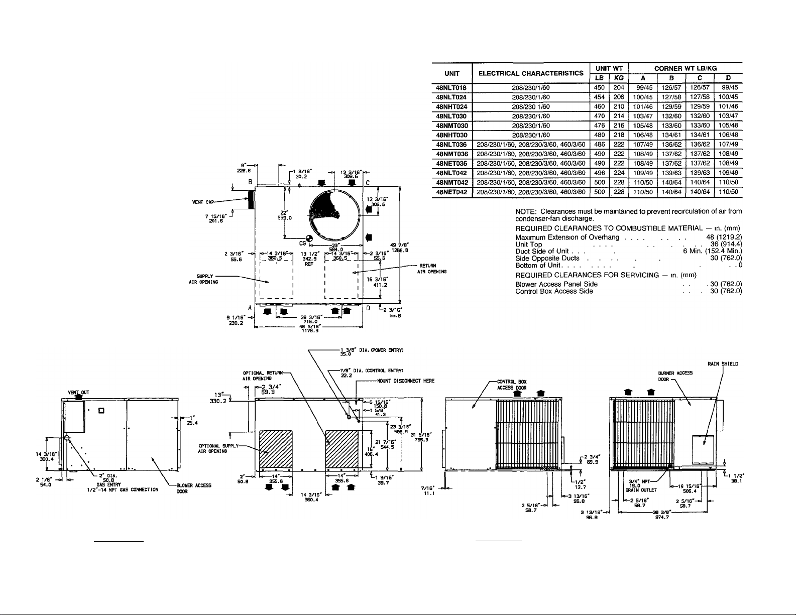
Fig. 2 — 48 Dimensional Drawing, Sizes NLT018 — NET042
UNIT
48NHT036
48NVT036
48NHT042
48NVT042
48NLT048
48NMT048
48NHT048
48NVT048
48NLT060
48NMT060
48NHT060
48NVT060
ELECTRICAL CHARACTERISTICS
208/230/1/60, 208/230/3/60, 460/3/60
208/230/1/60, 208/230/3/60, 460/3/60
208/230/1/60, 208/230/3/60, 460/3/60 550
208/230/1/60, 208/230/3/60. 460/3/60
208/230/1/60, 208/230/3/60, 460/3/60
208/230/1/60, 208/230/3/60, 460/3/60
208/230/1/60, 208/230/3/60, 460/3/60
208/230/1/60, 208/230/3/60, 460/3/60,
208/230/1/60, 208/230/3/60, 460/3/60
208/230/1/60, 208/230/3/60, 460/3/60
208/230/1/60, 208/230/3/60, 460/3/60 616 280 139/63
208/230/1/60, 208/230/3/60, 460/3/60 616
NOTE. Clearances must be maintained to prevent recirculation of air from
condenser-fan discharge.
REQUIRED CLEARANCES TO COMBUSTIBLE MATERIAL - in. (mm)
Maximum Extension of Overhang 48(1219.2)
Unit Top ........................... ■ .36(914.4)
Duct Side of Unit . .... 6 Min. (152.4 Min.)
Side Opposite Ducts .30 (762.0)
Bottom of Unit. .... .0
REQUIRED CLEARANCES FOR SERVICING - in. (mm)
Blower Access Panel Side ... . 30 (762.0)
Control Box Access Side . . 30 (762.0)
UNIT WT
LB
530
536 243 119/54 148/67
556
574
580 263 130/59
586 265 131/59 161/73
586
604
610
A B
KG
241 117/53 147/67
249 122/55 152/69
252
124/56 153/69
261 128/58
265
131/59
274
136/62 165/75
277
138/63 166/75
280
139/63
CORNER WT LB/KG
158/72
159/72
161/73
168/76
168/76
C
148/67 118/54
149/68 120/54
153/69
154/70 125/57
159/72
160/73
162/73
162/73
166/75
167/76
169/77
169/77
D
123/56
129/59
131/59
132/60
132/60
137/62
139/63
140/64
140/64
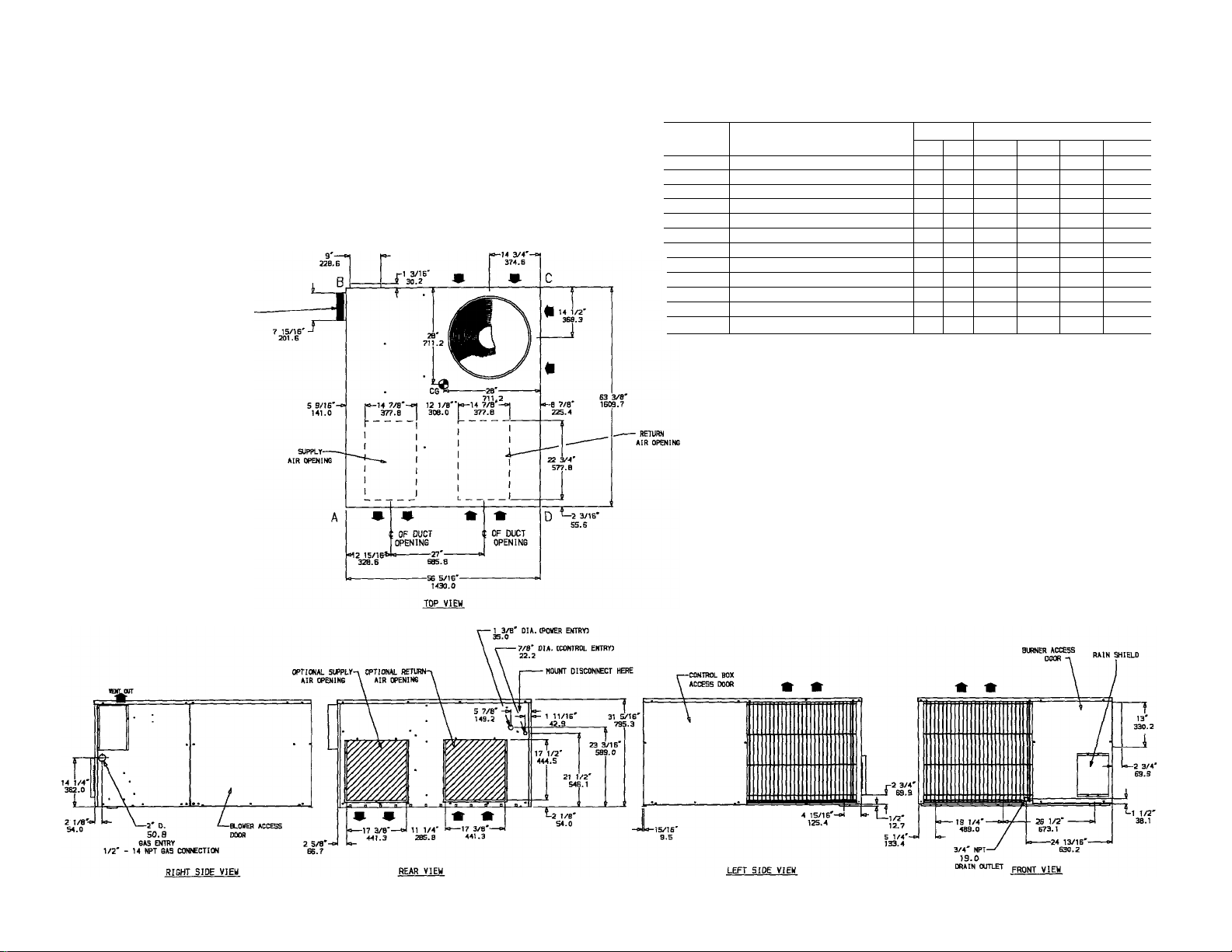
Fig. 3 — 48 Dimensional Drawing, Sizes NHT036 — NVT060
Table 1 — Physical Data
UNIT SIZE 48
NOMINAL CAPACITY (ton)
OPERATING WEIGHT (lb)
COMPRESSORS
Quantity
REFRIGERANT*
REFRIGERANT METERING DEVICE
CONDENSER COIL
Rows
FIns/in.
CONDENSER FAN
Nominal Airflow (Cfm)
Nominal Speed (Rpm)
Quantlty...Dlameter (in.)
Motor Hp (single-phase)
EVAPORATOR COIL
Rows
Fins/ln.
EVAPORATOR FAN
Nominal Cfm
Nominal Speed (Rpm)
Diameter x Width (in.)
Motor Hp (single-phase)
FURNACE SECTION
Burner Orifice No. (Qty...drlll size)
Burner Orifice No. (Qty...drlll size)
Pilot Orifice Diameter (in. ...drill size)
Pilot Orifice Diameter (In.)
RETURN-AIR FILTERS (sq ln.)t
Disposable
Cleanable
•Operating charge is iisted on unit namepiate
tRequired fieid-suppiied fliter areas are based on the iarger of the ARi-rated (Air Conditioning & Refrigeration institute) cooling airflow or the heating
airflow at a velocity of 300 ft/min for disposable type or 450 ft/min for high-capacity type Air filter pressure drop must not exceed 0.08 in wg
••Single-phase units
ttThree-phase units
(three-phase)
(three-phase)
Natural Gas
Propane Gas
Natural Gas
Propane Gas
NLT018 NLT024
IV2
450
1
20 20
600 800
2 44
2. 55 2 55
288
192
NHT024
2
454
10 X 8
2 44 3 44 2. 44 3 44
NLT030
460 470 476
2000
825
V10
'/3
-
3 55 2 55 3 55
NMT030 NHT030
2V2
Reciprocating Hermetic. 3500 Rpm
1000
528
352 416
AcouRater® Piston
niR 77
NLT036
480
R-22
1 20
3
14
1100
4 44
4 55 3 .55 4 55
NMT036
486
2
2500
1100
V4
1/4
1200
V2
V2
3 44 4 44 4 42 5.44
624 720
NET036 NHT036
490
10 X 10
3
490
4 54 5 55 6 55
530
Vio
Va
3/4
480
%
2500**
3000tt
825**
lioott
1200
NVT036
536
6 .44
i
Step 2 - Provide Unit Support
ROOF CURB — Install accessory roof curb in accordance
with instructions shipped with curb. Install insulation, cant
strips, roofing and flashing. Ductwork must be attached to
curb.
IMPORTANT: The gasketing of the unit to the roof
curb is critical for water integrity. Install gasketing
material supplied with the roof curb. Improperly ap
plied gasketing also can result in air leaks and poor
unit performance.
Curb should be level to within */4 inch. This is necessary
for unit drain to function properly. Refer to Accessory Roof
Curb Installation Instructions for additional information as
required.
SLAB MOUNT — Place the unit on a solid, level concrete
pad that is a minimum of 4-in. thick with 2-in. above grade.
The slab should extend approximately 2-in. beyond the cas
ing on all 4 sides of the unit. Install a gravel apron in front
of condenser-air inlets to prevent obstruction of airflow by
grass or shrubs. Do not secure the unit to the slab except
when required by local codes.
Step 3 — Provide Clearances — The required min
imum operating and service clearances are shown in Fig. 2
and 3. Adequate combustion, ventilation and condenser air
must be provided.
The condenser fan discharges through the top of the unit.
Be sure that the fan discharge does not recirculate to the
condenser coil. Do not locate the unit in either a corner or
under an overhead obstruction. The minimum clearance
under a partial overhang (such as a normal house overhang)
is 48-in. above the unit top. The maximum horizontal ex
tension of a partial overhang must not exceed 48 inches.
A CAUTION
Do not restrict condenser airflow. An air restriction at
either the outdoor-air inlet (the entire surface of the out
door coil) or the fan discharge can be detrimental to
compressor life.
Do not place the unit where water, ice or snow from an
overhang or roof will damage or flood the unit. Do not in
stall the unit on carpeting, tile or other combustible mate
rials. The unit may be installed on wood flooring or on Class
A, B or C roof covering materials.
Step 4 — Rig and Place Unit — Use spreader bars
and crate top when rigging the unit. The units must be rigged
for lifting as shown in Fig. 4. Refer to Fig. 4 for rigging
weight and Table 1 for operating weight. Use extreme cau
tion to prevent damage when moving the unit. Unit must
remain in an upright position during all rigging and mov
ing operations. The unit must be level for proper conden
sate drainage; therefore, the ground-level pad or accessory
roof-mounting curb must be level before setting the unit in
place. When a field-fabricated support is used, be sure that
the support is level and properly supports the unit.
A CAUTION
When installing the unit on a rooftop, be sure the roof
will support the additional weight. Refer to Fig. 4 for
corner weight information.
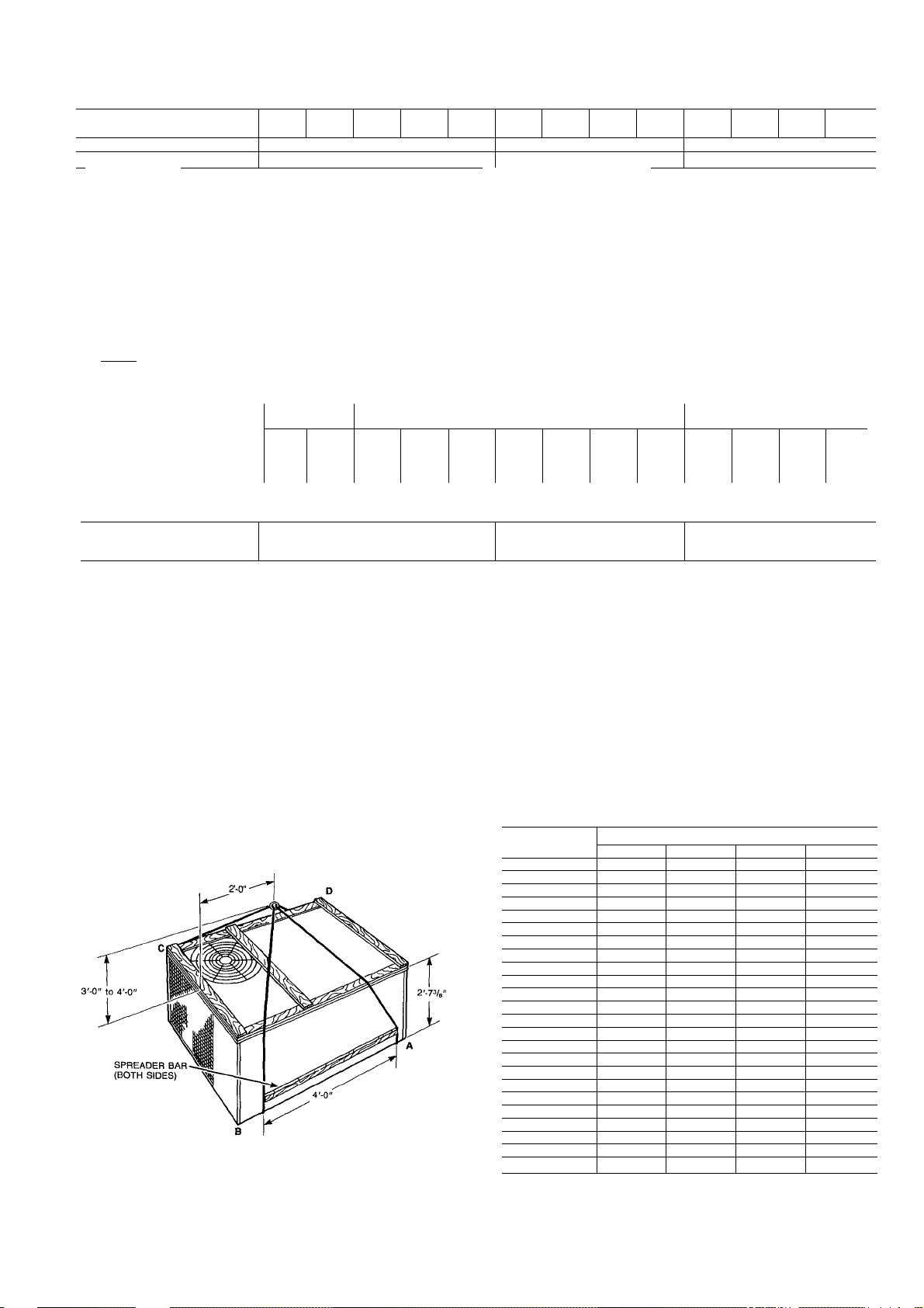
Table 1 — Physical Data (cent)
NLT
UNIT SIZE 48
NOMINAL CAPACITY (ton)
OPERATING WEIGHT (lb) 496 500 500
COMPRESSORS
Quantity______
REFRIGERANT*
REFRIGERANT METERING
DEVICE
CONDENSER COIL
Rows
FIns/ln.
CONDENSER FAN
Nominal Airflow (Cfm)
Nominal Speed (Rpm)
Quantlty...Dlameter (In.)
Motor Hp (single-phase)
EVAPORATOR COIL
Rows
Fins/ln.
EVAPORATOR FAN
Nominal Cfm
Nominal Speed (Rpm)
Diameter x Width (In.)
Motor Hp (single-phase)
FURNACE SECTION
Burner Orifice No.
Burner Orifice No.
Pilot Orifice Diameter
Pilot Orifice Diameter (In.)
RETURN-AIR FILTERS (sq ln.)t
Disposable 720
Cleanable 480
•Operating charge is iisted on unit namepiate
tRequired fieid-suppiied fiiter areas are based on the iarger of the ARi-rated (Air Conditioning & Refrigeration institute) cooling airflow or the heating airflow at a velocity of 300 ft/min
for disposable type or 450 ft/min for high-capacity type. Air filter pressure drop must not exceed 0 08 in wg
(three-phase)
_________
(three-phase)
(Qty...drlll size) Natural Gas
(Qty...drill size) Propane Gas
(In. ...drill size) Natural Gas
Propane Gas
3 44
3 55
NMT
042
2500 3000 3500
V2 3/4
’/2 3/4
4. 44
4 55 4 54 5 55
042
NET
042
3Vz
4 42 5 44
NHT
NVT
042
550
6 44
6. 55 3 .55 4 55 5 55 6 54 3 55
NLT
042
556 574 580
Reciprocating Hermetic, 3500 Rpm
3 44 4 44 5 44 6 42 3 44
NMT
048
R-22
AocuRater® Piston
018 77
NHT
048
048
4
586 586
1
2
20
009
816
544 640
NVT
048
NLT
060
604
NMT
4 44 5 44
4 55 5 55
060
610
5
2000
960
NHT
060
616
NVT
060
616
I 3450
6 42
6 54
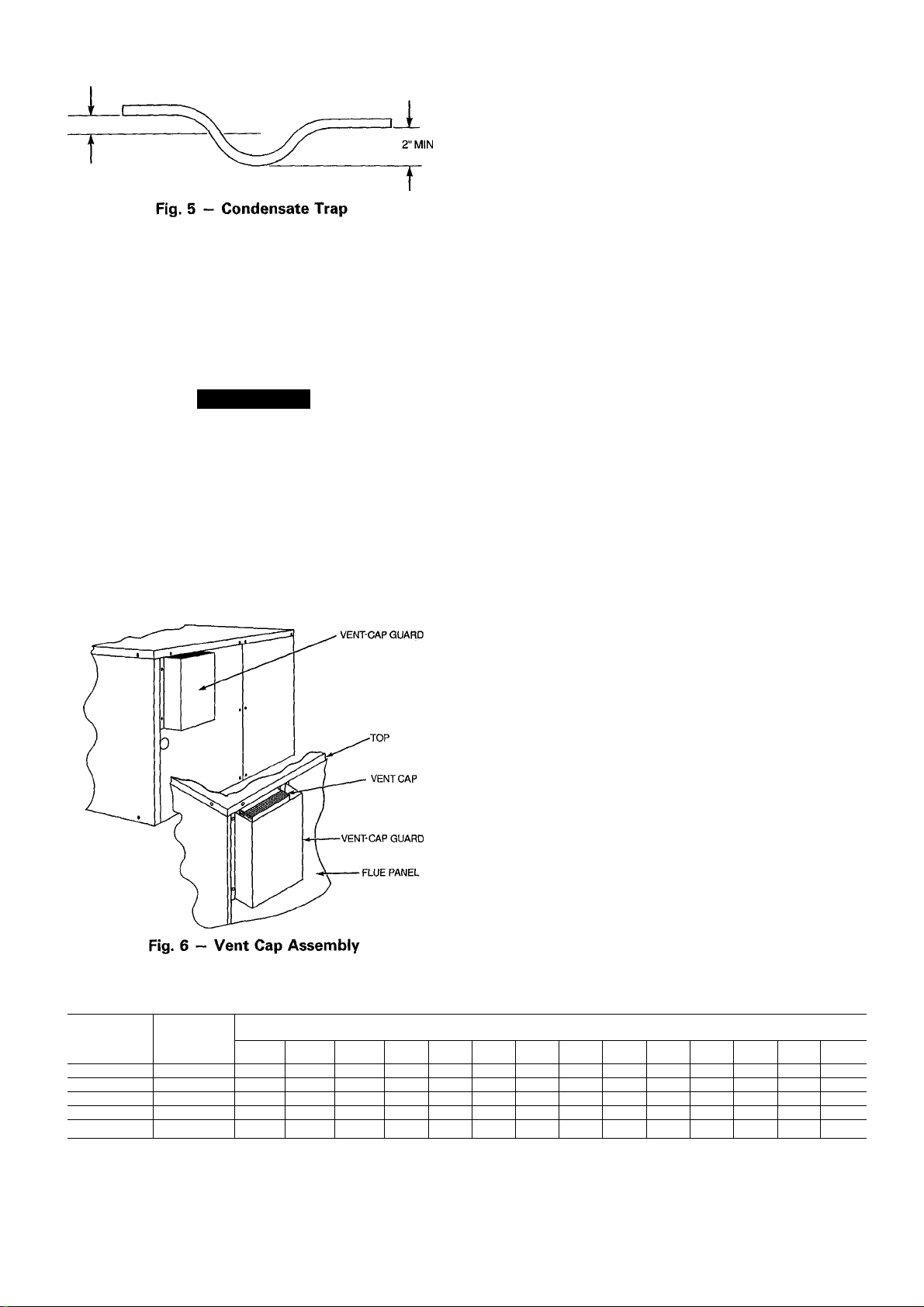
Step 5 — Connect Condensate Drain
NOTE: When installing condensate drain connection be sure
to comply with local codes and restrictions.
The unit disposes of condensate water through a %-in.
NPT drain fitting. See Fig. 2 and 3 for location.
Install a 2-in. trap at the drain fitting to ensure proper
drainage. See Fig. 5. Make sure the outlet of the trap is at
least one-in. lower than the unit drain pan connection to
Fig. 4 - Suggested Rigging
prevent the pan from overflowing. Prime the trap with
water.
If the installation requires draining the condensate water
away from the unit, connect a drain tube using a minimum
of %-in. OD copper tubing, y4-in. galvanized pipe or %-in.
plastic pipe. Do not undersize the tube. Pitch the drain tube
downward at a slope of at least one inch in every 10 ft of
horizontal run. Be sure to check the drain tube for leaks.
UNIT 48
NLT018
NLT024 100
NHT024
NLT030 103 132 132 103
NMT030 105 133 133 105
NHT030 106 134 134 106
NLT036
NMT036 108
NET036 108 137 137 108
NHT036 117 147 148 118
NVT036 119 148 149 120
NLT042 109 139 139 109
NMT042
NET042 110 140 140 110
NHT042 117
NVT042
NLT048 128
NMT048
NHT048
NVT048
NLT060
NMT060
NHT060
NVT060
A
99
101
107
110 140
124
130 159 160 131
131
131
136 165 166 137
138 166 167
139 168 169
139 168 169 140
CORNER WT (LB)
B C D
126 126 99
127
129 129 101
136 136
137 137
147 147 117
153
158 159 129
161
161
127
140
154
162
162
100
107
108
110
125
132
132
139
140
r MIN
Condensate water can be drained directly onto the roof in
rooftop installations (where permitted) or onto a gravel apron
in ground-level installations. When using a gravel apron,
make sure it slopes away from the unit.
Step 6 — Install Venting — The vent cap assembly
is shipped in the burner compartment. Remove the access
door to locate the assembly.
A CAUTION
The venting system is designed to ensure proper vent
ing. The vent cap assembly must be installed as indi
cated in this section of the unit Installation Instructions.
NOTE; Screw holes in the flue assembly and the unit flue
panel are not symmetrically located. Make sure they are
oriented properly when installing these components.
Refer to Fig. 6 and install the vent cap as follows:
1. Place vent cap assembly over flue panel. Orient screw
holes in vent cap with holes in flue panel.
2. Secure vent cap in place by inserting the single screw on
the right side of vent cap.
3. Place the vent cap guard over the vent cap. Orient holes
in vent cap guard with holes in vent cap and flue panel.
4. Secure the entire assembly with the remaining 2 screws
on the left side of vent cap and vent-cap guard
assembly.
Step 7 — Install Gas Piping — The gas supply pipe
enters the unit through the access hole provided. The gas
connection to the unit is made to the Vi-in. FPT gas inlet on
the manual shutoff or gas valve.
Install a separate gas supply line that runs directly from
the meter to the heating section. Refer to Table 2 and the
National Fuel Gas Code (NFGC) for gas pipe sizing. Do
not use cast-iron pipe. It is recommended that black iron
pipe is used. Check the local utility for recommendations
concerning existing lines. Choose a supply pipe that is large
enough to keep the pressure loss as low as practical. Never
use pipe smaller than the ‘A-in. FPT gas inlet on the unit
gas valve.
For natural gas applications, the gas pressure at unit gas
connection must not be less than 5 in. wg or greater than
13 in. wg while the unit is operating. For propane applica
tions, the gas pressure must not be less than 11 in. wg or
greater than 13 in. wg at the unit connection.
When installing the gas supply line, observe local codes
pertaining to gas pipe installations. Refer to the NFGC ANSI
(American National Standards Institute) Z223.1-1988 NFPA
(National Fire Protection Association) 54-1988 (in Canada,
CAN/CGA [Canadian Gas Association] B 149.1, (2)-M86).
In the absence of local building codes, adhere to the fol
lowing pertinent recommendations:
1. Avoid low spots in long runs of pipe. Grade all pipe
V4 inch in every 15 ft to prevent traps. Grade all hori
zontal runs downward to risers. Use risers to connect to
heating section and to meter.
2. Protect all segments of piping system against physical
and thermal damage. Support all piping with appropri
ate straps, hangers, etc. Use a minimum of one hanger
every 6 ft. For pipe sizes larger than Уг in., follow rec
ommendations of national codes.
3. Apply joint compound (pipe dope) sparingly and only to
male threads of joint when making pipe connections. Use
only pipe dope that is resistant to action of liquefied
petroleum gases as specified by local and/or national codes.
Never use Teflon tape.
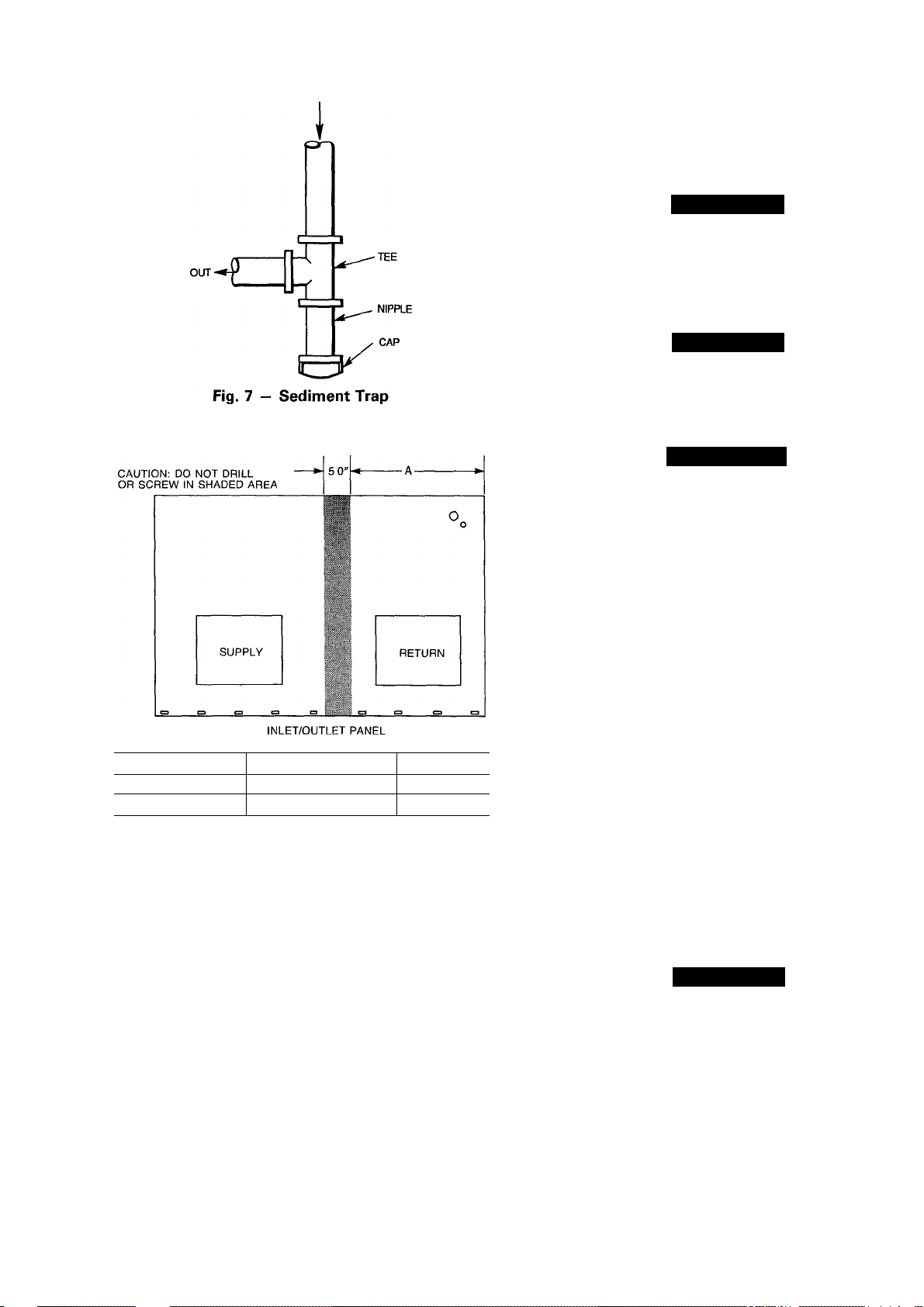
4. Install sediment trap in riser leading to heating section.
This drip leg functions as a trap for dirt and condensate.
Install trap where condensate cannot freeze. Install this
sediment trap by connecting a piping tee to riser leading
to heating section, so that straight-through section of tee
is vertical. See Fig. 7. Then, connect capped nipple into
lower end of tee. Extend capped nipple below level of
gas controls.
Table 2 — Maximum Gas Glow Capacity*
NOMINAL
IRON PIPE,
SIZE
(in.)
V2
%
1 1.049
VA 1.380
VA
‘Capacity of pipe in cu ft of gas per hr for gas pressure of 0 5 psig or less. Pressure drop of 0.5 in. wg
(based on a 0.60 specific gravity gas) Refer to Table C-4, NFPA 54-1984
fThls length includes an ordinary number of fittings
INTERNAL
DIAMETER
(In.)
.622 175 120
.824 360 250
1.610
10 20 30 40 50
680
1400 950
2100
97
465 375 320 285 260 240
1460
200
770 600 580
1180 990
82 73
170
151
900 810
LENGTH OF PIPE, FTf
60 70 80
61 57 53 50
66
125 118
138
530 490 460 430
220
750 690 650 620
90 100 125 150
110 103 93
205 195 175
400 360 325
44
160 145
550 500
175
—
40
84 77
300
460
200
—
72
135
280
430
IN
testing of the piping systems when test pressure in excess
of 0.5 psig. Pressure test the gas supply piping system at
pressures equal to or less than 0.5 psig. The unit heating
section must be isolated from the gas piping system by clos
ing the external main manual shutoff valve and slightly open
ing the ground-joint union.
A CAUTION
Unstable operation may occur when the gas valve and
manifold assembly are forced out of position while con
necting improperly-routed rigid gas piping to the gas
valve. Use a backup wrench when making connection
to avoid strain on, or distortion of, the gas control
piping.
A CAUTION
If a flexible conductor is required or allowed by the au
thority having jurisdiction, black iron pipe shall be in
stalled at the gas valve and shall extend a minimum of
2 in. outside the unit casing.
A WARNING
Never use a match or other open flame when checking
for gas leaks. Never purge gas line into combustion
chamber. Failure to follow this warning could result in
an explosion causing personal injury or death.
Size
Small Cabinet
Large Cabinet NHT036-NVT060 25V2 in.
NLT018-NET042 20V2 in.
"A"
Fig. 8 — Location of Coii Area Not to be Drilled
5. Install an accessible, external, manual main shutoff valve
in gas supply pipe within 6 ft of heating section.
6. Install ground-joint union close to heating section be
tween unit manual shutoff and external manual main shut
off valve.
7. Pressure-test all gas piping in accordance with local and
national plumbing and gas codes before connecting pip
ing to unit.
NOTE; Pressure test the gas supply system after the gas
supply piping is connected to the gas valve. The supply
piping must be disconnected from the gas valve during the
8. Check for gas leaks at the field-installed and factoryinstalled gas lines after all piping connections have been
completed. Use soap-and-water solution (or method spec
ified by local codes and/or regulations).
Step 8 — Install Duct Connections — The unit
has duct flanges on the supply- and return-air openings on
the side and bottom of the unit. See Fig. 2 and 3 for con
nection sizes and locations.
NOTE: The design and installation of the duct system must
be in accordance with the standards of the NFPA for instal
lation of nonresidence-type air conditioning and ventilating
systems, NFPA No. 90A orresidence-type, NFPA No. 90B;
and/or local codes and residence-type, NFPA No. 90B; and/
or local codes and ordinances.
Adhere to the following criteria when selecting, sizing
and installing the duct system;
1. The unit is shipped in vertical configuration. To convert
unit to horizontal application, remove side duct covers,
save screws and install the covers on bottom duct
openings.
2. Select and size ductwork, supply-air registers and returnair grilles according to ASHRAE (American Society of
Heating, Refrigeration and Air Conditioning Engineers)
recommendations.
A CAUTION
When drilling the duct-system fastening holes into the
side of the unit instead of the unit duct flanges, use ex
treme care to avoid puncturing the coil or coil tubes.
See Fig. 8.
3. Use flexible transition between rigid ductwork and unit
to prevent transmission of vibration. The transition may
be screwed or bolted to duct flanges. Use suitable gas
kets to ensure weather- and airtight seal.
4. Install external, field-supplied air filter(s) in return-air
ductwork where it is easily accessible for service. Rec
ommended filter sizes are shown in Table 1,
5. Size all ductwork for maximum required airflow (either
heating or cooling) for unit being installed. Avoid abrupt
duct size increases or decreases.
6. Adequately insulate and weatherproof all ductwork lo
cated outdoors. Insulate ducts passing through uncondi
tioned space, and use vapor barrier in accordance with
latest issue of SMACNA (Sheet Metal and Air Condi
tioning Contractors National Association) and ACCA (Air
Conditioning Contractors of America) minimum instal
lation standards for heating and air conditioning sys
tems. Secure all ducts to building structure,
7. Flash, weatherproof and vibration-isolate all openings
in building structure in accordance with local codes and
good building practices.
Step 9 — Install Electrical Connections
A WARNING
The unit cabinet must have an uninterrupted, unbroken
electrical ground to minimize the possibility of per
sonal injury if an electrical fault should occur. This ground
may consist of an electrical wire connected to the unit
ground lug in the control compartment, or conduit ap
proved for electrical ground when installed in accor
dance with NEC (National Electrical Code) ANSI/
NFPA (latest edition) (in Canada, Canadian Electrical
Code CSA C22.1) and local electrical codes. Do not
use gas piping as an electrical ground. Failure to ad
here to this warning could result in personal injury or
death.
A CAUTION
Failure to follow these precautions could result in dam
age to the unit being installed:
1. Make all electrical connections in accordance with NEC
ANSI/NFPA (latest edition) and local electrical codes
governing such wiring. In Canada, all electrical connec
tions must be in accordance with CSA Standard C22.1
Canadian Electrical Code Part 1 and applicable local codes.
Refer to unit wiring diagram.
2. Use only copper conductor for connections between field-
supplied electrical disconnect switch and unit. DO NOT
USE ALUMINUM WIRE.
3. Be sure that high-voltage power to unit is within oper
ating voltage range indicated on unit rating plate. On 3phase units, ensure that phases are balanced within 2%.
Consult local power company for correction of im
proper voltage and/or phase balance.
4. Insulate low-voltage wires for highest voltage contained
within conduit when low-voltage control wires are run
in same conduit as high-voltage wires.
5. Do not damage internal components when drilling through
any panel to mount electrical hardware, conduit, etc.
HIGH-VOLTAGE CONNECTIONS - The unit must have
a separate electrical service with a field-supplied, water
proof, fused disconnect switch mounted at, or within sight
from, the unit. Refer to the unit rating plate for maximum
fuse/circuit breaker size and minimum circuit amps (ampac
ity) for wire sizing. See Table 3 for electrical data.
The field-supplied disconnect switch box may be mounted
on the unit over the high-voltage inlet hole in the control
corner panel. See Fig. 2 and 3.
Proceed as follows to complete the high-voltage connec
tions to the unit;
1. Connect ground lead to chassis ground connection when
using separate ground wire.
2. Run high-voltage leads into unit control box and con
nect to contactor. See unit wiring label, and Fig. 9.
A CAUTION
TRANSFORMER CONTAINS AUTO
RESET OVERCURRENT PROTECTOR.
IT MAY RESET WITHOUT WARNING
STARTING HEATING OR COOLING
SECTION OF THIS PRODUCT.
DISCONNECT POWER PRIOR TO
SERVICING.
THIS COMPARTMENT MUST BE
CLOSED EXCEPT WHEN SERVICING.
316056-201 REV A
Fig. 9 — Transformer Label
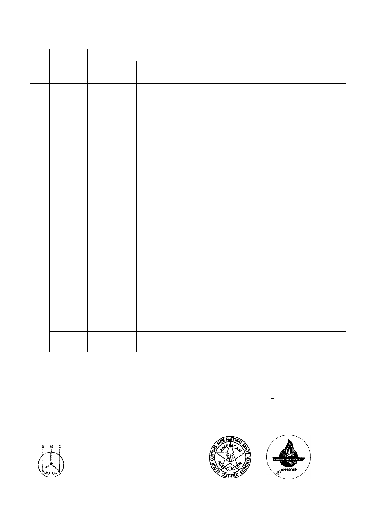
Table 3 — Electrical Data
UNIT
SIZE
01B
024
030
036
042
048
060
AWG
FLA
LRA
MCA
MOCP
NEC
RLA
NOTES:
1
In compliance with NEC requirements for multimotor and combination load
and equipment (refer to NEC Articles 430 and 440), the overcurrent pro
tective device for the unit shall be fuse or HACR breaker
Unbalanced 3-Phase Supply Voltage
Never operate a motor where a phase imbalance in supply voltage is greater
than 2% Use the following formula to determine the % voltage imbalance.
% Voltage Imbalance
_ y max voltage deviation from average voltage
NOMINAL
V-PH-HZ
208/230-1-60
208/230-1-60
208/230-1-60
208/230-1-60
208/230-3-60
460-3-60
208/230-1-60
208/230-3-60
460-3-60
208/230-1-60
208/230-3-60
460-3-60
208/230-1-60
208/230-3-60
460-3-60
American Wire Gage
Full Load Amps
Locked Rotor Amps
Minimum Circuit Amps
Maximum Overcurrent Protection
National Electrical Code
Rated Load Amps
Example: Supply voltage is 460-3-60
MODEL NO.
48
NLT018 187 253 82 49 0
NLT024
NHT024
NLT030
NMT030
NHT030
NLT036
NMT036
NET036
NHT036
NVT036
NLT036
NMT036
NET036
NHT036
NVT036
NLT036
NMT036
NET036
NHT036
NVT036
NLT042
NMT042
NET042
NHT042
NVT042
NLT042
NMT042
NET042
NHT042
NVT042
NLT042
NMT042
NET042
NHT042
NVT042
NLT048
NMT048
NHT048
NVT048
NLT048
NMT048
NHT048
NVT048
NLT048
NMT048
NHT048
NVT048
NLT060
NMT060
NHT060
NVT060
NLT060
NMT060
NHT060
NVT060
NLT060
NMT060
NHT060
NVT060
average voltage
AB = 452 volts
BC = 464 volts
AC = 455 volts
Average Voltage
VOLTAGE
RANGE
Min Max RLA
187 253
187 253 14.3
187
187
414
187
187
414 506 77 41 0 1 2
187 253 26 5
187 253 16.8
187
187 253 30 7
187
414 506 104 55 0 1 2
452 + 464 -r 455
3
1371
—JT— =457
11.6
11.6
253 21 1
14.7
253
506 7 1
23.9 95.4 1 5
253
15.3
253
253
253
82
21 4
COMPR
LRA
61 0
61.0
86.0 08
100 0 1 5
67.0
34 0
82 0
1140
84 0
42 0 1 2
135 0
130 0 22
CONDENSER-
FAN MOTOR
FLA
08
08
1 9
1.9
1.9
22
22
1.2
1.9
1 9
1 9
2.2
2.2
2.1
22
2 1
Determine maximum deviation from average voltage.
(AB) 457 - 452 =5 volts
(BC) 464 - 457 =7 volts
(AC) 457 - 455 =2 volts
Maximum deviation is 7 volts.
Determine % voltage imbalance
% Voltage Imbalance =100 x
This amount of phase imbalance is satisfactory as it is below the maximum
allowable 2%
IMPORTANT: If the supply voltage phase imbalance is more than 2%,
contact your local electric utility company immediately
EVAPORATOR-
FAN MOTOR
FLA
2.5
2.5 12 17 1 25
25
25
3.0
30
3.0
45
45
45
30
30
45
45
45
1 5
1 5
23
23
23
3.0
3.0
45
45
4.5
30
3.0
45
4.5
4.5
1 5
1 5
23
23
2.3
4.5
45
4.5
62
45
45
4.5
62
23
23
2.3
32
62 6 46 7
6.2
32 12 17.4 25
AWG MIN
WIRE SIZE
7
"457
14
10
8
10
14
8
10
14
8
6
10
14
8
= 1.53%
POWER SUPPLY
MCA
13 6 20
21 2
21.2
21 7
30.9
30 9
32.4
32 4
32.4
23.3
23 3
24 8
25 1
25 1
11 6
11 6
124
124
12.4
34 3
34 3
35 9
35.9
35 9
24 0
24.0
25 5
25.8
25 8
123
12.3
13 1
13.1
13 1
39 7
39 7
39.7
41 4
27.7
27 7
27 7
29 4
13.8
138
138
147
35 5 50
MOCP
30
40
30
15
50
35
35
40
40
40
20
60
40
20
60
Loading...