


48AJ,AK,AW,AY020-060 with Reciprocating Compressor 48EJ,EK,EW,EY024-068 Single Package Rooftop Units Electric Cooling/Gas Heating
Installation, Start-Up and
Service Instructions
CONTENTS
Page SAFETY CONSIDERATIONS . . . . . . . . . . . . . . . . . . . . . . 1 INSTALLATION . . . . . . . . . . . . . . . . . . . . . . . . . . . . . . . . 1-58
Step 1 — Provide Unit Support . . . . . . . . . . . . . . . . . . . 1
•ROOF CURB
•ALTERNATE UNIT SUPPORT
Step 2 — Rig and Place Unit . . . . . . . . . . . . . . . . . . . . . 2
•POSITIONING
•ROOF MOUNT
Step 3 — Field Fabricate Ductwork . . . . . . . . . . . . . . . 2
Step 4 — Make Unit Duct Connections . . . . . . . . . . . 2
Step 5 — Install Flue Hood . . . . . . . . . . . . . . . . . . . . . . 28
Step 6 — Trap Condensate Drain . . . . . . . . . . . . . . . . 28
Step 7 — Install Gas Piping . . . . . . . . . . . . . . . . . . . . . 28 Step 8 — Controls Options . . . . . . . . . . . . . . . . . . . . . . 29
•STAGED GAS UNIT APPLICATIONS
•THERMISTORS
•CONSTANT VOLUME APPLICATIONS
•VARIABLE AIR VOLUME (VAV) APPLICATIONS
Step 9 — Make Electrical Connections . . . . . . . . . . 33
•POWER WIRING
•FIELD POWER SUPPLY
•FIELD CONTROL WIRING
Step 10 — Make Outdoor-Air Inlet
Adjustments . . . . . . . . . . . . . . . . . . . . . . . . . . . . . . . . . . 48
•ECONOMIZER
•ECONOMIZER SETTINGS
Step 11 — Position Power Exhaust/Barometric
Relief Damper Hood. . . . . . . . . . . . . . . . . . . . . . . . . . . 52
Step 12 — Install All Accessories . . . . . . . . . . . . . . . 54
Step 13 — Field Modifications. . . . . . . . . . . . . . . . . . . 57
START-UP . . . . . . . . . . . . . . . . . . . . . . . . . . . . . . . . . . . . 58-89
SERVICE . . . . . . . . . . . . . . . . . . . . . . . . . . . . . . . . . . . . 89-102
TROUBLESHOOTING. . . . . . . . . . . . . . . . . . . . . . . 103-115
START-UP CHECKLIST . . . . . . . . . . . . . . . . . . . CL-1,CL-2
SAFETY CONSIDERATIONS
Installation and servicing of air-conditioning equipment can be hazardous due to system pressure and electrical components. Only trained and qualified service personnel should install, repair, or service air-conditioning equipment.
Untrained personnel can perform the basic maintenance functions of cleaning coils and filters and replacing filters. All other operations should be performed by trained service personnel. When working on air-conditioning equipment, observe precautions in the literature, tags and labels attached to the unit, and other safety precautions that may apply.
Follow all safety codes. Wear safety glasses and work gloves. Use quenching cloth for unbrazing operations. Have fire extinguishers available for all brazing operations.
Before performing service or maintenance operations on unit, turn off main power switch to unit. Electrical shock could cause personal injury.
1.Improper installation, adjustment, alteration, service, or maintenance can cause property damage, personal injury, or loss of life. Refer to the User’s Information Manual provided with this unit for more details.
2.Do not store or use gasoline or other flammable vapors and liquids in the vicinity of this or any other appliance.
What to do if you smell gas:
1.DO NOT try to light any appliance.
2.DO NOT touch any electrical switch, or use any phone in your building.
3.IMMEDIATELY call your gas supplier from a neighbor’s phone. Follow the gas supplier’s instructions.
4.If you cannot reach your gas supplier, call the fire department.
Disconnect gas piping from unit when pressure testing at pressure greater than 0.5 psig. Pressures greater than 0.5 psig will cause gas valve damage resulting in hazardous condition. If gas valve is subjected to pressure greater than 0.5 psig, it must be replaced before use. When pressure testing field-supplied gas piping at pressures of 0.5 psig or less, a unit connected to such piping must be isolated by closing the manual gas valve(s).
INSTALLATION
Step 1 — Provide Unit Support
1.All panels must be in place when rigging.
2.Unit is not designed for handling by fork truck.
Manufacturer reserves the right to discontinue, or change at any time, specifications or designs without notice and without incurring obligations.
Book |
1 |
PC 111 |
Catalog No. 534-739 |
Printed in U.S.A. |
Form 48A,E-1SI |
Pg 1 |
107 |
11-01 |
Replaces: 48E-6SI |
Tab |
1a |
|
|
|
|
|
|
|
|
|
|
|
|
|
|
|
|
|
|

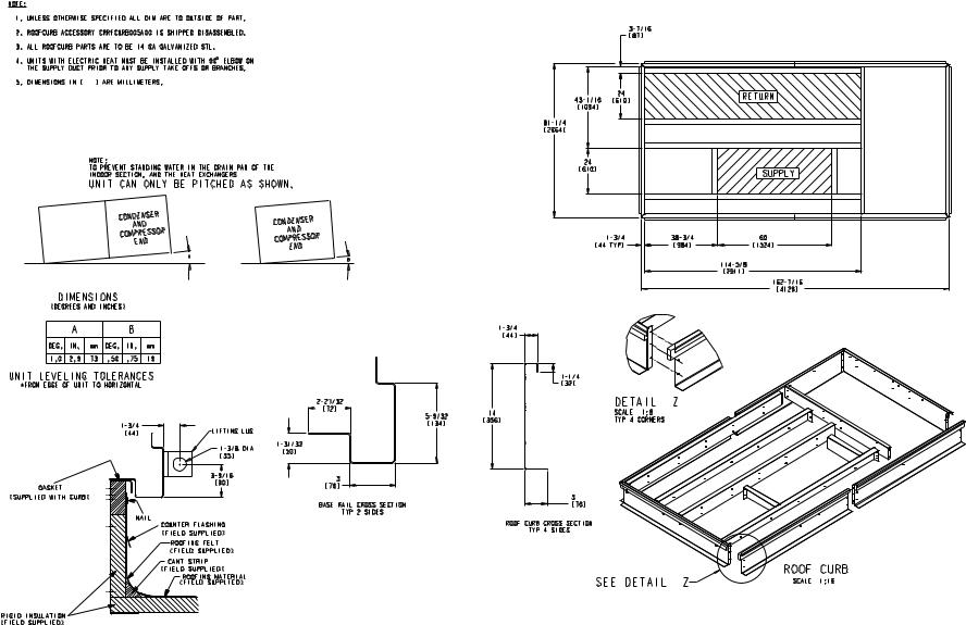
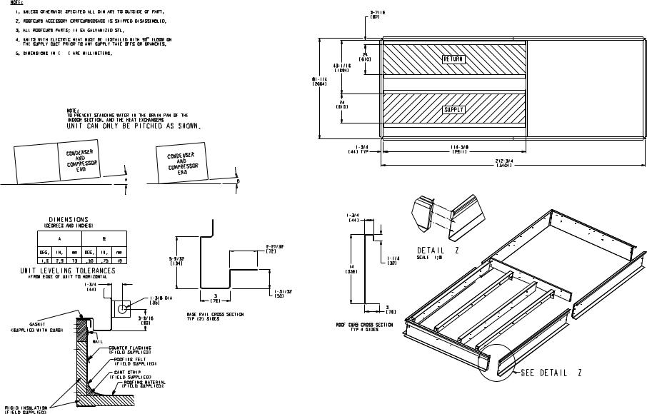
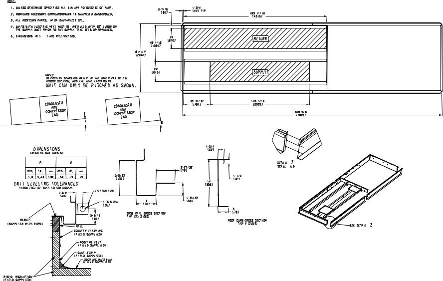
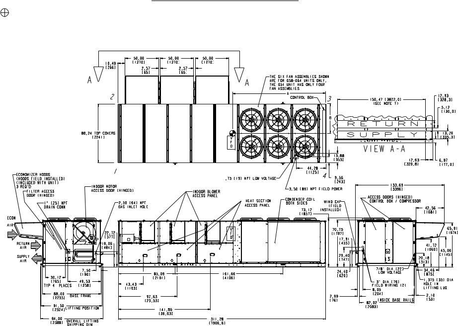
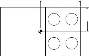
ROOF CURB — For vertical discharge units, assemble or install accessory roof curb in accordance with instructions shipped with this accessory. See Fig. 1-4. Install insulation, cant strips, roofing, and counter flashing as shown. Ductwork can be installed to roof curb before unit is set in place. Curb should be level. This is necessary to permit unit drain to function properly. Unit leveling tolerance is shown in Fig. 1-3. Refer to Accessory Roof Curb Installation Instructions for additional information as required. When accessory roof curb is used, unit may be installed on class A, B, or C roof covering material.
IMPORTANT: The gasketing of the unit to the roof curb is critical for a watertight seal. Install gasket with the roof curb as shown in Fig. 1-3. Improperly applied gasket can also result in air leaks and poor unit performance.
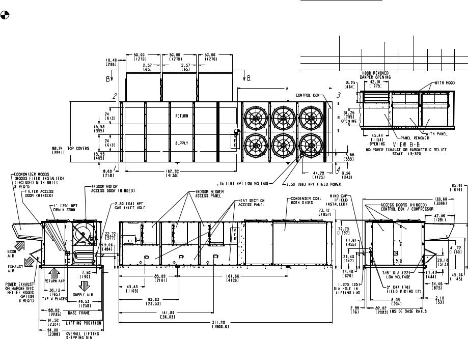
ALTERNATE UNIT SUPPORT — When the preferred curb or slab mount cannot be used, support unit with sleepers on perimeter, using unit curb support area. If sleepers cannot be used, support long sides of unit (refer to Fig. 5-16) with a minimum number of 4-in. x 4-in. pads spaced as follows: 48AJ,AK,AW,AY020-030 and 48EJ,EK,EW,EY024-034 units require 3 pads on each side; 48AJ,AK,AW,AY035-050 and 48EJ,EK,EW,EY038-048 units require 4 pads on each side; 48AJ,AK,AW,AY060 and 48EJ,EK,EW,EY054-068 units require 6 pads on each side. Unit may sag if supported by corners only.
Step 2 — Rig and Place Unit — Inspect unit for transportation damage. See Tables 1A and 1B for physical data. File any claim with transportation agency.
Do not drop unit; keep upright. Use spreader bars over unit to prevent sling or cable damage. Level by using unit frame as a reference; leveling tolerance is shown in Fig. 1-3. See Fig. 17 for additional information. Unit operating weight is shown in Table 2.
NOTE: On retrofit jobs, ductwork may be attached to old unit instead of roof curb. Be careful not to damage ductwork when removing old unit. Attach existing ductwork to roof curb instead of unit.
Four lifting lugs are provided on the unit base rails as shown in Fig. 5-16. Refer to rigging instructions on unit.
POSITIONING — Maintain clearance, per Fig. 5-16, around and above unit to provide minimum distance from combustible materials, proper airflow, and service access.
Do not install unit in an indoor location. Do not locate unit air inlets near exhaust vents or other sources of contaminated air. For proper unit operation, adequate combustion and ventilation air must be provided in accordance with Section 5.3 (Air for Combustion and Ventilation) of the National Fuel Gas Code, ANSI Z223.1 (American National Standards Institute).
Although unit is weatherproof, guard against water from higher level runoff and overhangs.
Locate mechanical draft system flue assembly at least 4 ft from any opening through which combustion products could enter the building, and at least 4 ft from any adjacent building.
When unit is located adjacent to public walkways, flue assembly must be at least 7 ft above grade.
ROOF MOUNT — Check building codes for weight distribution requirements. See Fig. 17. Unit operating weight is shown in Table 2.
Step 3 — Field Fabricate Ductwork — Secure all ducts to building structure. Use flexible duct connectors between unit and ducts as required. Insulate and weatherproof all external ductwork, joints, and roof openings with counter flashing and mastic in accordance with applicable codes.
NOTE: Due to width of the horizontal supply/return ductwork, provisions should be made for servicing of the outdoor air filters (i.e., catwalk over ductwork).
Ducts passing through an unconditioned space must be insulated and covered with a vapor barrier. Outlet grilles must not lie directly below unit discharge. The return duct must have a 90-degree elbow before opening into the building space if the unit is equipped with power exhaust.
To attach ductwork to roof curb, insert duct approximately 10 to 11 in. up into roof curb. Connect ductwork to 14-gage roof curb material with sheet metal screws driven from inside the duct.
For vertical supply and return units, tools or parts could drop into ductwork and cause an injury. Install a 90-degree elbow turn in the supply and return ductwork between the unit and the conditioned space. If a 90-degree elbow cannot be installed, then a grille of sufficient strength and density should be installed to prevent objects from falling into the conditioned space.
Step 4 — Make Unit Duct Connections
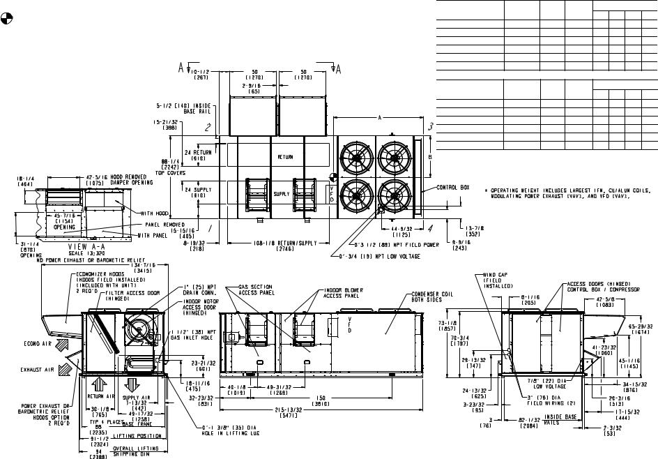
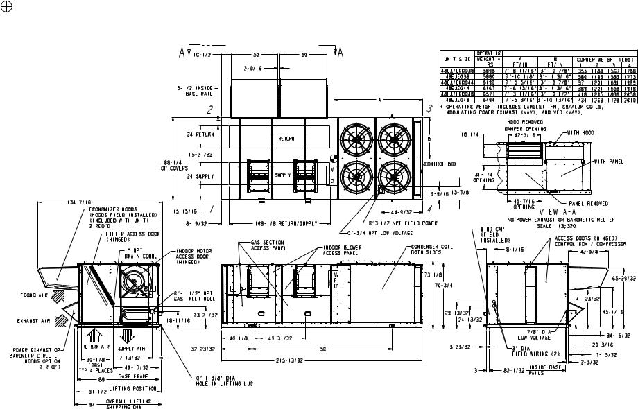
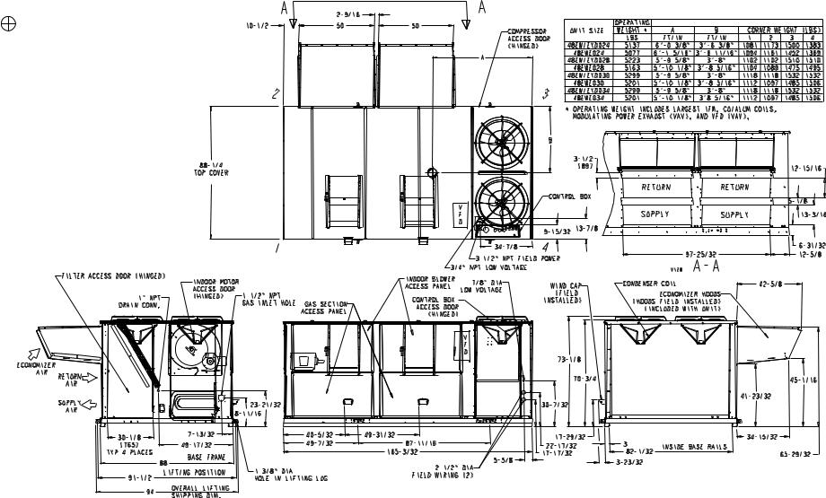
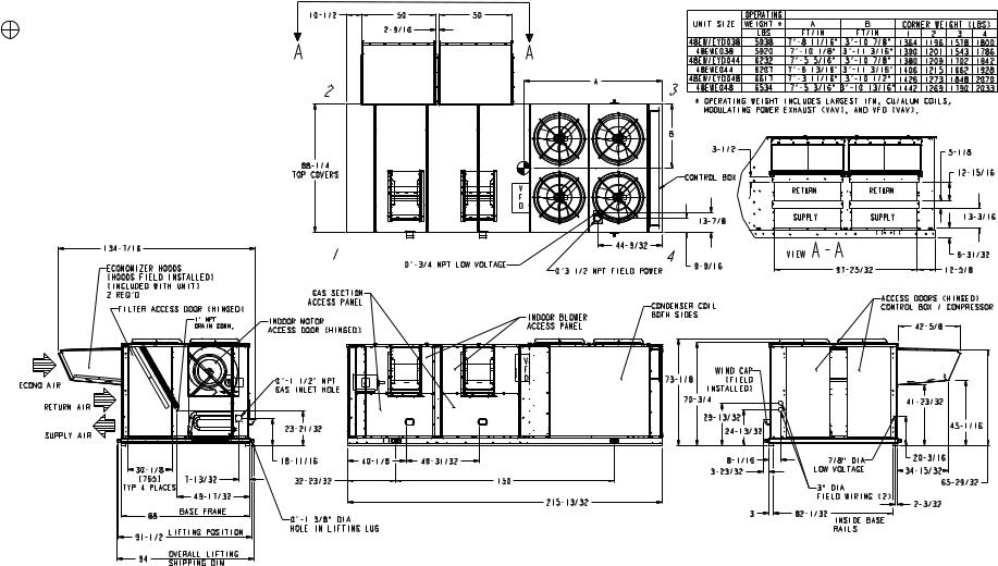
48AJ,AK,EJ,EK UNITS — Unit is shipped for through-the- bottom duct connections. Field-fabricated ductwork should be attached to the roof curb. Supply and return duct dimensions are shown in Fig. 5-7 and 11-13. Air distribution is shown in Fig. 18 and 19. Refer to installation instructions shipped with roof curb for more information.
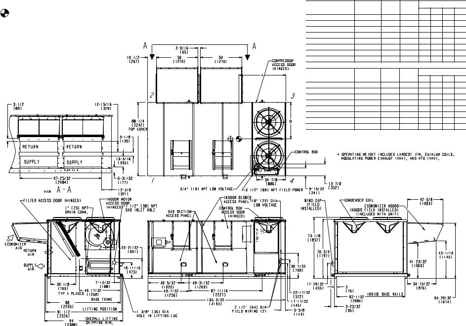
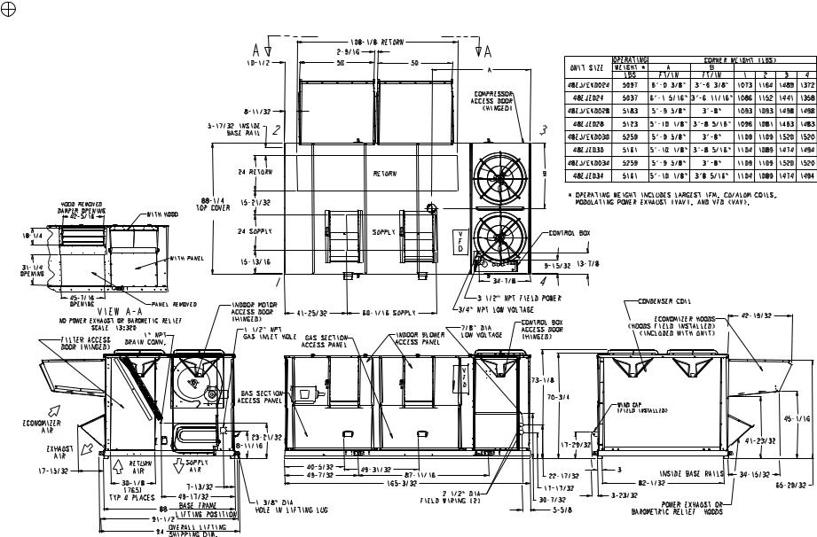
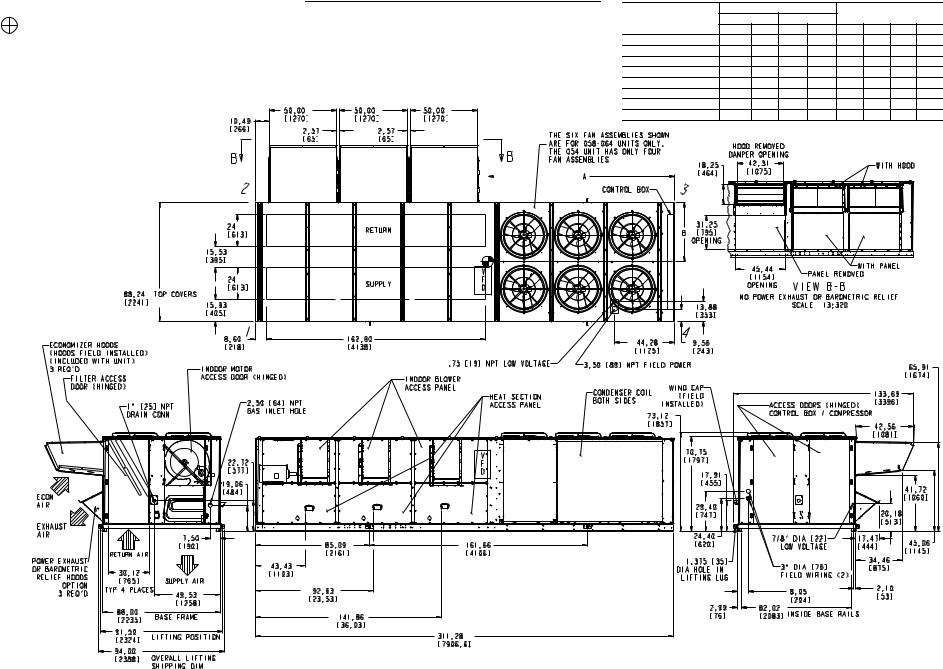
48AW,AY,EW,EY UNITS — Remove shipping covers from supply and return air openings. Attach field-supplied ductwork to unit. Connect to the unit with a single duct for all supply openings and with a single duct for all return openings. Splitting of the airflow into branch ducts should not be done at the unit. Sufficient duct length should be used prior to branching to ensure the air temperatures are well mixed within the ductwork. See Fig. 8-10 and 14-16 for duct opening dimensions. Secure all ducts to building structure. Air distribution is shown in Fig. 8-10 and 14-16.
Install accessory barometric relief or power exhaust in the field-fabricated return ductwork. Refer to Step 11 — Position Power Exhaust/Barometric Relief Damper Hood section on page 52 for more information.
Instructions continued on page 28.
2
3
Fig. 1 — Roof Curb — 48AJ,AK020-030 and 48EJ,EK024-034 Units
4
Fig. 2 — Roof Curb — 48AJ,AK034-050 and 48EJ,EK038-048 Units
5
Fig. 3 — Roof Curb — 48AJ,AK060 and 48EJ,EK054-068 Units

NOTES:
1.Unless otherwise specified, all dimensions are to outside of part.
2.Seal strip to be placed covering reference holes.
3.Phantom lines represent seal strip. Total length required is 75 linear ft.
4.If existing seal strip around roof curb seems damaged, replace it. Total length required is 62 linear ft.
5.Five crossrails are field located per dimensions shown and secured using self-tapping screws.
6.48A and 48E series units will overhang existing “DD” or “DF” roof curbs by 2.98″ at indoor motor end and 15.08″ at compressor end.
7.Ductwork (field supplied) must be notched to clear three crossrails.
8. Dimensions in [ ] are millimeters.
6
Fig. 4 — Roof Curb Adapter — (48AJ,AK060 and 48EJ,EK054-068 Units on 48DD,DF054-064 Retrofit, Part No. CRRCADPT005A00)

NOTES: |
|
OPERATING |
|
|
CORNER WEIGHT (lbs) |
|||||
1. |
Weights include economizer (standard). |
UNIT SIZE |
A |
B |
||||||
|
|
WEIGHT* |
(ft-in.) |
(ft-in.) |
1 |
2 |
3 |
4 |
||
2. |
Center of Gravity. |
|
(lbs) |
|||||||
|
|
|
||||||||
3. |
Do not locate adjacent units with flue discharge facing economizer |
48AJ/AK (Low Heat) 020 |
5142 |
6- 03/8 |
3-63/16 |
1082 |
1174 |
1502 |
1384 |
|
48AJ (High Heat) 020 |
5222 |
6- 15/16 |
3-611/16 |
1126 |
1194 |
1494 |
1408 |
|||
|
inlet. |
|||||||||
|
Min Clearances to be: |
48AJ/AK (Low Heat) 025 |
5228 |
5- 95/8 |
3-8 |
1103 |
1103 |
1511 |
1511 |
|
|
Adjacent Units: 15′-0″ [4572]. |
48AJ (High Heat) 025 |
5308 |
5-103/32 |
3-85/16 |
1135 |
1120 |
1516 |
1537 |
|
|
Top of Units: No Overhang. |
|||||||||
|
Condenser Coil: 4′-0″ [1219]. |
48AJ/AK (Low Heat) 027 |
5325 |
5- 95/8 |
3-8 |
1123 |
1123 |
1539 |
1539 |
|
|
Economizer Side: 6′-0″ [1829]. |
|
|
|
|
|
|
|
|
|
|
Heat Side: 4′-0″ [1219]. |
48AJ (High Heat) 027 |
5405 |
5-103/32 |
3-85/16 |
1156 |
1140 |
1544 |
1565 |
|
4. |
Filter Access Side: 10′-0″ [3048]. (For removal of evaporator coil.) |
48AJ/AK (Low Heat) 030 |
5325 |
5- 95/8 |
3-8 |
1123 |
1123 |
1539 |
1539 |
|
For smaller service and operational clearances contact Carrier Appli- |
48AJ (High Heat) 030 |
5405 |
5-103/32 |
3-85/16 |
1156 |
1140 |
1544 |
1565 |
||
|
cation Engineering Department. |
|||||||||
5.Bottom ducts designed to be attached to accessory roof curb. If unit is mounted on dunnage, it is recommended the ducts must be sup-
ported by cross braces as done on accessory roof curb. |
UNIT SIZE |
OPERATING |
A (mm) |
B (mm) |
CORNER WEIGHT (kg) |
|||
6. Dimensions are in inches [mm]. |
WEIGHT* |
1 |
2 |
3 |
4 |
|||
|
|
(kg) |
|
|
||||
|
48AJ/AK (Low Heat) 020 |
2332 |
1839 |
1072 |
491 |
533 |
681 |
628 |
|
48AJ (High Heat) 020 |
2369 |
1862 |
1085 |
511 |
542 |
678 |
639 |
|
48AJ/AK (Low Heat) 025 |
2371 |
1768 |
1118 |
500 |
500 |
686 |
686 |
|
48AJ (High Heat) 025 |
2408 |
1781 |
1125 |
515 |
508 |
688 |
697 |
|
48AJ/AK (Low Heat) 027 |
2415 |
1768 |
1118 |
509 |
509 |
698 |
698 |
|
48AJ (High Heat) 027 |
2452 |
1781 |
1125 |
524 |
517 |
700 |
710 |
|
48AJ/AK (Low Heat) 030 |
2415 |
1768 |
1118 |
509 |
509 |
698 |
698 |
|
48AJ (High Heat) 030 |
2452 |
1781 |
1125 |
524 |
517 |
700 |
710 |
7
Fig. 5 — Base Unit Dimensions — 48AJ,AK020-030
NOTES: |
|
|
|
OPERATING |
|
|
CORNER WEIGHT (lbs) |
|||||
1. |
Weights include economizer (standard). |
UNIT SIZE |
A |
B |
||||||||
|
|
|
|
WEIGHT* |
(ft-in.) |
(ft-in.) |
1 |
2 |
3 |
4 |
||
2. |
Center of Gravity. |
|
(lbs) |
|||||||||
|
|
|
||||||||||
48AJ/AK (Low Heat) 035 |
6004 |
7-811/16 |
3-107/8 |
1380 |
1209 |
1595 |
1820 |
|||||
3. |
Do not locate adjacent units with flue discharge facing economizer |
|||||||||||
|
inlet. |
|
|
48AJ (High Heat) 035 |
6164 |
7-101/8 |
3-113/16 |
1447 |
1251 |
1607 |
1859 |
|
|
Min Clearances to be: |
48AJ/AK (Low Heat) 040 |
6514 |
7-55/16 |
3-107/8 |
1442 |
1264 |
1779 |
2030 |
|||
|
Adjacent Units: 15′-0″ [4572]. |
48AJ (High Heat) 040 |
6674 |
7-613/16 |
3-113/16 |
1512 |
1307 |
1787 |
2068 |
|||
|
Top of Units: No Overhang. |
|||||||||||
|
Condenser Coil: 4′-0″ [1219]. |
48AJ/AK (Low Heat) 050 |
6725 |
7-311/16 |
3-101/2 |
1449 |
1294 |
1878 |
2104 |
|||
|
Economizer Side: 6′-0″ [1829]. |
48AJ (High Heat) 050 |
6885 |
7-53/16 |
3-1013/16 |
1519 |
1337 |
1886 |
2142 |
|||
|
′ |
″ |
[1219]. |
|||||||||
|
Heat Side: 4 -0 |
|
|
|
|
|
|
|
|
|
||
|
Filter Access Side: 10′-0″ [3048]. (For removal of evaporator coil.) |
|
|
|
|
|
|
|
|
|||
4. |
For smaller service and operational clearances contact Carrier Appli- |
|
OPERATING |
|
|
|
|
|
|
|||
5. |
cation Engineering Department. |
UNIT SIZE |
A (mm) |
B (mm) |
CORNER WEIGHT (kg) |
|||||||
Bottom ducts designed to be attached to accessory roof curb. If unit is |
WEIGHT* |
1 |
2 |
3 |
4 |
|||||||
|
mounted on dunnage, it is recommended the ducts must be supported |
|
(kg) |
|
|
|||||||
|
by cross braces as done on accessory roof curb. |
48AJ/AK (Low Heat) 035 |
2723 |
2355 |
1191 |
626 |
548 |
723 |
826 |
|||
6. |
Dimensions are in inches [mm]. |
|||||||||||
48AJ (High Heat) 035 |
2796 |
2390 |
1199 |
656 |
567 |
729 |
843 |
|||||
|
|
|
|
|||||||||
|
|
|
|
48AJ/AK (Low Heat) 040 |
2955 |
2268 |
1191 |
654 |
573 |
807 |
921 |
|
|
|
|
|
48AJ (High Heat) 040 |
3027 |
2306 |
1199 |
686 |
593 |
811 |
938 |
|
|
|
|
|
48AJ/AK (Low Heat) 050 |
3050 |
2228 |
1181 |
657 |
587 |
852 |
954 |
|
|
|
|
|
48AJ (High Heat) 050 |
3123 |
2266 |
1189 |
689 |
607 |
856 |
972 |
|
8
Fig. 6 — Base Unit Dimensions — 48AJ,AK035-050
NOTES: |
|
5. Bottom ducts designed to be attached to accessory roof curb. If unit is mounted |
||
1. Weights include economizer (standard). |
|
on dunnage, it is recommended the ducts must be supported by cross braces as |
||
2. |
Center of Gravity. |
|
done on accessory roof curb. |
|
|
6. Base unit weights include outdoor air hoods and filters (indoor fan motor is not |
|||
3. Do |
not locate adjacent units with flue |
dis- |
included). Add indoor motor, FIOPs and accessories for total operating weight. |
|
7. VAV motor weights include indoor motor, VFD, compressor electric unloaders, |
||||
charge facing economizer inlet. |
|
|||
|
VFD transducer and associated wiring. |
|||
Min Clearances to be: |
|
|||
|
8. Dimensions are in inches [mm]. |
|||
|
Adjacent Units: 15′-0″ [4572]. |
|
||
Top of Units: No Overhang. |
|
|
||
Condenser Coil: 4′-0″ [1219]. |
|
|
||
Economizer Side: 6′-0″ [1829]. |
|
|
||
Heat Side: 4′-0″ [1219]. |
|
|
||
Filter Access Side: 15′-0″ [4572]. (For |
|
|||
removal of evaporator coil.) |
|
|
||
4. For smaller service and operational clear- |
|
|||
ances contact Carrier Application Engineer- |
|
|||
ing Department. |
|
|
||
BASE UNIT WEIGHTS (See Note 6) lbs (kg)
|
|
|
060 |
|
|
|
|
|
|
48AJD/AKD |
8930 (4051) |
|
|
|
|
|
|
||
48AJE |
9170 (4159) |
|
|
|
|
|
|
||
|
|
|
|
|
|||||
|
|
CENTER OF GRAVITY |
|
% OF TOTAL WEIGHT |
|||||
UNIT SIZE |
|
ft-in. |
Millimeters |
AT EACH CORNER |
|||||
|
|
A |
B |
A |
B |
1 |
2 |
3 |
4 |
48AJD/AKD060 10-711/16 3-1019/32 3242 1184 21.7 19.3 27.7 31.2
48AJE060 |
11-211/16 4-19/32 |
3422 1235 23.9 19.4 25.4 31.3 |
|||
|
|
|
|
|
|
|
|
|
|
|
|
|
|
|
|
|
|
|
|
|
|
|
|
|
|
|
|
|
|
|
|
|
|
|
|
|
|
|
|
|
|
9
Fig. 7 — Base Unit Dimensions — 48AJ,AK060
NOTES: |
|
|
|
OPERATING |
|
|
CORNER WEIGHT (lbs) |
|||||
1. Weights include economizer (standard). |
UNIT SIZE |
A |
B |
|||||||||
|
|
|
|
WEIGHT* |
(ft-in.) |
(ft-in.) |
1 |
2 |
3 |
4 |
||
2. |
Center of Gravity. |
|
(lbs) |
|||||||||
|
|
|
||||||||||
48AW/AY (Low Heat) 020 |
5182 |
6- 03/8 |
3-63/16 |
1090 |
1183 |
1514 |
1395 |
|||||
3. Do not locate adjacent units with flue discharge facing economizer |
||||||||||||
|
inlet. |
|
|
48AW (High Heat) 020 |
5262 |
6- 15/16 |
3-611/16 1134 |
1203 |
1505 |
1419 |
||
|
Min Clearances to be: |
48AW/AY (Low Heat) 025 |
5268 |
5- 95/8 |
3-8 |
1111 |
1111 |
1523 |
1523 |
|||
|
Adjacent Units: 15′-0″ [4572]. |
48AW (High Heat) 025 |
5348 |
5-101/8 |
3-85/16 |
1144 |
1128 |
1527 |
1548 |
|||
|
Top of Units: No Overhang. |
|||||||||||
|
Condenser Coil: 4′-0″ [1219]. |
48AW/AY (Low Heat) 027 |
5365 |
5- 95/8 |
3-8 |
1132 |
1132 |
1551 |
1551 |
|||
|
Economizer Side: 6′-0″ [1829]. |
48AW (High Heat) 027 |
5445 |
5-101/8 |
3-85/16 |
1165 |
1149 |
1555 |
1577 |
|||
|
′ |
″ |
[1219]. |
|||||||||
|
Heat Side: 4 -0 |
|
|
|
|
|
|
|
|
|
||
|
Filter Access Side: 10′-0″ [3048]. (For removal of evaporator coil.) |
48AW/AY (Low Heat) 030 |
5365 |
5- 95/8 |
3-8 |
1132 |
1132 |
1551 |
1551 |
|||
4. For smaller service and operational clearances contact Carrier |
48AW (High Heat) 030 |
5445 |
5-101/8 |
3-85/16 |
1165 |
1149 |
1555 |
1577 |
||||
|
Application Engineering Department. |
|||||||||||
5. Dimensions are in inches [mm]. |
|
|
|
|
|
|
|
|
||||
|
|
|
|
UNIT SIZE |
OPERATING |
A (mm) |
B (mm) |
CORNER WEIGHT (kg) |
||||
|
|
|
|
WEIGHT* |
1 |
2 |
3 |
4 |
||||
|
|
|
|
|
(kg) |
|
|
|||||
|
|
|
|
48AW/AY (Low Heat) 020 |
2351 |
1839 |
1072 |
495 |
537 |
687 |
633 |
|
|
|
|
|
48AW (High Heat) 020 |
2387 |
1862 |
1085 |
515 |
546 |
683 |
644 |
|
|
|
|
|
48AW/AY (Low Heat) 025 |
2390 |
1768 |
1118 |
504 |
504 |
691 |
691 |
|
|
|
|
|
48AW (High Heat) 025 |
2426 |
1781 |
1125 |
519 |
512 |
693 |
702 |
|
|
|
|
|
48AW/AY (Low Heat) 027 |
2434 |
1768 |
1118 |
513 |
513 |
704 |
704 |
|
|
|
|
|
48AW (High Heat) 027 |
2470 |
1781 |
1125 |
528 |
521 |
705 |
715 |
|
|
|
|
|
48AW/AY (Low Heat) 030 |
2434 |
1768 |
1118 |
513 |
513 |
704 |
704 |
|
|
|
|
|
48AW (High Heat) 030 |
2470 |
1781 |
1125 |
528 |
521 |
705 |
715 |
|
10
Fig. 8 — Base Unit Dimensions — 48AW,AY020-030
NOTES:
1.Weights include economizer (standard).
2. Center of Gravity.
3.Do not locate adjacent units with flue discharge facing economizer inlet.
Min Clearances to be:
Adjacent Units: 15′-0″ [4572].
Top of Units: No Overhang. Condenser Coil: 4′-0″ [1219]. Economizer Side: 6′-0″ [1829]. Heat Side: 4′-0″ [1219].
Filter Access Side: 10′-0″ [3048]. (For removal of evaporator coil.)
4.For smaller service and operational clearances contact Carrier Application Engineering Department.
5.Dimensions are in inches [mm].
11
UNIT SIZE |
OPERATING |
A |
B |
CORNER WEIGHT (lbs) |
|||
WEIGHT* |
(ft-in.) |
(ft-in.) |
1 |
2 |
3 |
4 |
|
|
(lbs) |
||||||
|
|
|
|||||
48AW/AY (Low Heat) 035 |
6044 |
7- 811/16 |
3-107/8 |
1389 |
1217 |
1606 |
1832 |
48AW (High Heat) 035 |
6204 |
7-101/8 |
3-113/16 |
1456 |
1259 |
1617 |
1871 |
48AW/AY (Low Heat) 040 |
6554 |
7- 311/16 |
3-107/8 |
1451 |
1271 |
1790 |
2042 |
48AW (High Heat) 040 |
6714 |
7- 613/16 |
3-113/16 |
1521 |
1315 |
1798 |
2080 |
48AW/AY (Low Heat) 050 |
6765 |
7- 311/16 |
3-101/2 |
1458 |
1301 |
1889 |
2117 |
48AW (High Heat) 050 |
6925 |
7- 53/16 |
3-1013/16 1528 |
1345 |
1897 |
2155 |
|
UNIT SIZE |
OPERATING |
A (mm) |
B (mm) |
CORNER WEIGHT (kg) |
|||
WEIGHT* |
1 |
2 |
3 |
4 |
|||
|
(kg) |
|
|
||||
48AW/AY (Low Heat) 035 |
2741 |
2355 |
1191 |
630 |
552 |
728 |
831 |
48AW (High Heat) 035 |
2814 |
2390 |
1199 |
661 |
571 |
734 |
849 |
48AW/AY (Low Heat) 040 |
2973 |
2268 |
1191 |
658 |
577 |
812 |
926 |
48AW (High Heat) 040 |
3045 |
2306 |
1199 |
690 |
596 |
816 |
944 |
48AW/AY (Low Heat) 050 |
3069 |
2228 |
1181 |
661 |
590 |
857 |
960 |
48AW (High Heat) 050 |
3141 |
2266 |
1189 |
693 |
610 |
860 |
977 |
Fig. 9 — Base Unit Dimensions — 48AW,AY035-050
NOTES:
1.Weights include economizer (standard).
2. Center of Gravity.
3.Do not locate adjacent units with flue discharge facing economizer inlet.
Min Clearances to be:
Adjacent Units: 15′-0″ [4572].
Top of Units: No Overhang. Condenser Coil: 4′-0″ [1219]. Economizer Side: 6′-0″ [1829]. Heat Side: 4′-0″ [1219].
Filter Access Side: 15′-0″ [4572]. (For removal of evaporator coil.)
4.For smaller service and operational clearances contact Carrier Application Engineering Department.
12
5.Base unit weights include outdoor air hoods and filters (indoor fan motor is not included). Add indoor motor, FIOPs and accessories for total operating weight.
6.VAV motor weights include indoor motor, VFD, compressor electric unloaders, VFD transducer and associated wiring.
7.Dimensions are in inches [mm].
8.For side-supply/return applications, a single return and supply ductwork connection
is recommended for covering all three return and all three supply openings. The entire area around the duct openings is available for a 1.5″ duct flange attachment.
BASE UNIT WEIGHTS (See Note 6) lbs (kg)
|
|
060 |
|
|
|
|
|
|
48AWD/AYD |
8970 (4069) |
|
|
|
|
|
|
|
48AWE |
9210 (4178) |
|
|
|
|
|
|
|
|
|
|
|
|||||
|
CENTER OF GRAVITY |
|
% OF TOTAL WEIGHT |
|||||
UNIT SIZE |
|
ft-in. |
Millimeters |
AT EACH CORNER |
||||
|
A |
B |
A |
B |
1 |
2 |
3 |
4 |
48AWD/AYD060 10-711/16 3-1019/32 3242 1184 21.7 19.3 27.7 31.2
48AWE060 |
11-211/16 4-19/32 |
3422 1235 23.9 19.4 25.4 31.3 |
Fig. 10 — Base Unit Dimensions — 48W,AY060
NOTES:
1.Weights include economizer (standard).
2. Center of Gravity.
3.Do not locate adjacent units with flue discharge facing economizer inlet.
Min Clearances to be:
Adjacent Units: 15′-0″ [4572].
Top of Units: No Overhang. Condenser Coil: 4′-0″ [1219]. Economizer Side: 6′-0″ [1829]. Heat Side: 4′-0″ [1219].
Filter Access Side: 10′-0″ [3048]. (For removal of evaporator coil.)
4.For smaller service and operational clearances contact Carrier Application Engineering Department.
5.Bottom ducts designed to be attached to accessory roof curb. If unit is mounted on dunnage, it is recommended the ducts must be supported by cross braces as done on accessory roof curb.
6.Dimensions are in inches [mm].
13
Fig. 11 — Base Unit Dimensions — 48EJ,EK024-034
NOTES:
1.Weights include economizer (standard).
2. Center of Gravity.
3.Do not locate adjacent units with flue discharge facing economizer inlet.
Min Clearances to be:
Adjacent Units: 15′-0″ [4572].
Top of Units: No Overhang. Condenser Coil: 4′-0″ [1219]. Economizer Side: 6′-0″ [1829]. Heat Side: 4′-0″ [1219].
Filter Access Side: 10′-0″ [3048]. (For removal of evaporator coil.)
4.For smaller service and operational clearances contact Carrier Application Engineering Department.
5.Bottom ducts designed to be attached to accessory roof curb. If unit is mounted on dunnage, it is recommended the ducts must be supported by cross braces as done on accessory roof curb.
6.Dimensions are in inches [mm].
14
Fig. 12 — Base Unit Dimensions — 48EJ,EK038-048
NOTES:
1.Weights include economizer (standard).
2. Center of Gravity.
3.Do not locate adjacent units with flue discharge facing economizer inlet.
Min Clearances to be:
Adjacent Units: 15′-0″ [4572].
Top of Units: No Overhang. Condenser Coil: 4′-0″ [1219]. Economizer Side: 6′-0″ [1829]. Heat Side: 4′-0″ [1219].
Filter Access Side: 15′-0″ [4572]. (For removal of evaporator coil.)
4.For smaller service and operational clearances contact Carrier Application Engineering Department.
5.Bottom ducts designed to be attached to accessory roof curb. If unit is mounted on dunnage, it is recommended the ducts must be supported by cross braces as done on accessory roof curb.
6.Base unit weights include outdoor air hoods and filters (indoor fan motor is not included). Add indoor motor, FIOPs and accessories for total operating weight.
7.VAV motor weights include indoor motor, VFD, compressor electric unloaders, VFD transducer and associated wiring.
8.Dimensions in are in inches [mm].
15
BASE UNIT WEIGHTS (See Note 6) lbs (kg)
|
|
|
054 |
058 |
|
064 |
068 |
|
|||
|
48EJD/EKD |
6805 (3087) |
7055 (3200) |
|
7305 (3314) |
7480 (3393) |
|||||
|
|
48EJE |
7045 (3196) |
7295 (3309) |
|
7545 (3422) |
7720 (3502) |
||||
|
|
|
|
|
|
|
|
|
|
|
|
|
|
|
|
|
|
|
|
|
|
|
|
|
|
|
|
|
|
|
|
|
|
|
|
|
|
|
|
|
|
|
|
|
|
|
|
|
|
|
|
|
|
|
|
|
|
|
|
|
|
|
|
|
|
|
|
|
|
|
|
|
CENTER OF GRAVITY |
% OF TOTAL WEIGHT |
||||||
UNIT SIZE |
Inches |
Millimeters |
AT EACH CORNER |
|||||
|
A |
B |
A |
B |
1 |
2 |
3 |
4 |
48EJD/EKD054 |
130.9 |
46.9 |
3325 |
1192 |
22.4 |
19.6 |
27.0 |
30.9 |
48EJE054 |
133.8 |
47.4 |
3397 |
1204 |
23.1 |
19.8 |
26.3 |
30.7 |
48EJD/EKD058 |
132.1 |
47.5 |
3354 |
1207 |
22.9 |
19.5 |
26.5 |
31.1 |
48EJE058 |
139.5 |
49.6 |
3544 |
1260 |
25.3 |
19.6 |
24.1 |
31.1 |
48EJD/EKD064 |
125.3 |
45.2 |
3181 |
1149 |
20.7 |
19.6 |
29.1 |
30.7 |
48EJE064 |
132.2 |
47.2 |
3359 |
1199 |
22.8 |
19.7 |
26.7 |
30.8 |
48EJD/EKD068 |
127.7 |
46.6 |
3242 |
1184 |
21.7 |
19.3 |
27.7 |
31.2 |
48EJE068 |
134.7 |
48.6 |
3422 |
1235 |
23.9 |
19.4 |
25.4 |
31.3 |
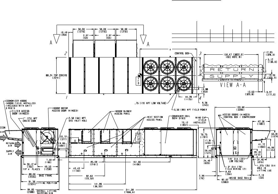
Fig. 13 — Base Unit Dimensions — 48EJ,EK054-068
NOTES:
1.Weights include economizer (standard).
2. Center of Gravity.
3.Do not locate adjacent units with flue discharge facing economizer inlet.
Min Clearances to be:
Adjacent Units: 15′-0″ [4572].
Top of Units: No Overhang. Condenser Coil: 4′-0″ [1219]. Economizer Side: 6′-0″ [1829]. Heat Side: 4′-0″ [1219].
Filter Access Side: 15′-0″ [4572]. (For removal of evaporator coil.)
4.For smaller service and operational clearances contact Carrier Application Engineering Department.
5.Dimensions in are in inches [mm].
16
Fig. 14 — Base Unit Dimensions — 48EW,EY024-034
NOTES:
1.Weights include economizer (standard).
2. Center of Gravity.
3.Do not locate adjacent units with flue discharge facing economizer inlet.
Min Clearances to be:
Adjacent Units: 15′-0″ [4572].
Top of Units: No Overhang. Condenser Coil: 4′-0″ [1219]. Economizer Side: 6′-0″ [1829]. Heat Side: 4′-0″ [1219].
Filter Access Side: 15′-0″ [4572]. (For removal of evaporator coil.)
4.For smaller service and operational clearances contact Carrier Application Engineering Department.
5.Dimensions in are in inches [mm].
17
Fig. 15 — Base Unit Dimensions — 48EW,EY038-048
NOTES:
1.Weights include economizer (standard).
2. Center of Gravity.
3.Do not locate adjacent units with flue discharge facing economizer inlet.
Min Clearances to be:
Adjacent Units: 15′-0″ [4572].
Top of Units: No Overhang. Condenser Coil: 4′-0″ [1219]. Economizer Side: 6′-0″ [1829]. Heat Side: 4′-0″ [1219].
Filter Access Side: 15′-0″ [4572]. (For removal of evaporator coil.)
4.For smaller service and operational clearances contact Carrier Application Engineering Department.
5.Base unit weights include outdoor air hoods and filters (indoor fan motor is not included). Add indoor motor, FIOPs and accessories for total operating weight.
6.VAV motor weights include indoor motor, VFD, compressor electric unloaders, VFD transducer and associated wiring.
7.For side-supply/return applications, a single return and supply ductwork connection is recommended for covering all three return and all
three supply openings. The entire area around the duct openings is available for a 1.5″ duct flange attachment
8.Dimensions in are in inches [mm].
18
BASE UNIT WEIGHTS (See Note 6) lbs (kg)
|
|
054 |
|
058 |
|
064 |
068 |
|||||
48EWD/EYD |
6845 (3105) |
7095 (3218) |
7345 (3332) |
7520 (3411) |
||||||||
48EWE |
7085 (3214) |
7335 (3327) |
7585 (3441) |
7760 (3520) |
||||||||
|
|
|
|
|
|
|
|
|
|
|
|
|
|
|
|
|
|
|
|
|
|
|
|
|
|
|
|
|
|
|
|
|
|
|
|
|
|
|
|
|
|
|
|
|
|
|
|
|
|
|
|
|
|
|
|
|
|
|
|
|
|
|
|
|
|
|
|
|
|
|
|
|
|
|
|
|
|
|
|
|
|
|
|
|
|
|
|
|
|
|
|
|
|
|
|
|
|
|
|
|
|
|
|
|
CENTER OF GRAVITY |
% OF TOTAL WEIGHT |
||||||
UNIT SIZE |
Inches |
Millimeters |
AT EACH CORNER |
|||||
|
A |
B |
A |
B |
1 |
2 |
3 |
4 |
48EWD/EYD054 |
130.9 |
46.9 |
3325 |
1192 |
22.4 |
19.6 |
27.0 |
30.9 |
48EWE054 |
133.8 |
47.4 |
3397 |
1204 |
23.1 |
19.8 |
26.3 |
30.7 |
48EWD/EYD058 |
132.1 |
47.5 |
3354 |
1207 |
22.9 |
19.5 |
26.5 |
31.1 |
48EWE058 |
139.5 |
49.6 |
3544 |
1260 |
25.3 |
19.6 |
24.1 |
31.1 |
48EWD/EYD064 |
125.3 |
45.2 |
3181 |
1149 |
20.7 |
19.6 |
29.1 |
30.7 |
48EWE064 |
132.2 |
47.2 |
3359 |
1199 |
22.8 |
19.7 |
26.7 |
30.8 |
48EWD/EYD068 |
127.7 |
46.6 |
3242 |
1184 |
21.7 |
19.3 |
27.7 |
31.2 |
48EWE068 |
134.7 |
48.6 |
3422 |
1235 |
23.9 |
19.4 |
25.4 |
31.3 |
Fig. 16 — Base Unit Dimensions — 48EW,EY054-068
2 |
A |
3 |
B
1 4
48AJ,AK,AW,AY UNITS
|
|
CENTER OF GRAVITY |
|
|
PERCENT OF TOTAL WEIGHT |
|
|||
UNIT |
Inches |
|
Millimeters |
|
AT EACH CORNER (%) |
|
|||
|
A |
|
B |
A |
B |
1 |
2 |
3 |
4 |
48AJ,AKD020 |
72.4 |
|
42.2 |
1839 |
1072 |
21.0% |
22.8% |
29.2% |
26.9% |
48AJE020 |
73.3 |
|
42.7 |
1862 |
1085 |
21.6% |
22.9% |
28.6% |
27.0% |
48AW,AYD020 |
72.4 |
|
42.2 |
1839 |
1072 |
21.0% |
22.8% |
29.2% |
26.9% |
48AWE020 |
73.3 |
|
42.7 |
1862 |
1085 |
21.6% |
22.9% |
28.6% |
27.0% |
48AJ,AKD025 |
69.6 |
|
44.0 |
1768 |
1118 |
21.1% |
21.1% |
28.9% |
28.9% |
48AJE025 |
70.1 |
|
44.3 |
1781 |
1125 |
21.4% |
21.1% |
28.6% |
29.0% |
48AW,AYD025 |
69.6 |
|
44.0 |
1768 |
1118 |
21.1% |
21.1% |
28.9% |
28.9% |
48AWE025 |
70.1 |
|
44.3 |
1781 |
1125 |
21.4% |
21.1% |
28.6% |
29.0% |
48AJ,AKD027 |
69.6 |
|
44.0 |
1768 |
1118 |
21.1% |
21.1% |
28.9% |
28.9% |
48AJE027 |
70.1 |
|
44.3 |
1781 |
1125 |
21.4% |
21.1% |
28.6% |
29.0% |
48AW,AYD027 |
69.6 |
|
44.0 |
1768 |
1118 |
21.1% |
21.1% |
28.9% |
28.9% |
48AWE027 |
70.1 |
|
44.3 |
1781 |
1125 |
21.4% |
21.1% |
28.6% |
29.0% |
48AJ,AKD030 |
69.6 |
|
44.0 |
1768 |
1118 |
21.1% |
21.1% |
28.9% |
28.9% |
48AJE030 |
70.1 |
|
44.3 |
1781 |
1125 |
21.4% |
21.1% |
28.6% |
29.0% |
48AW,AYD030 |
69.6 |
|
44.0 |
1768 |
1118 |
21.1% |
21.1% |
28.9% |
28.9% |
48AWE030 |
70.1 |
|
44.3 |
1781 |
1125 |
21.4% |
21.1% |
28.6% |
29.0% |
48AJ,AKD035 |
92.7 |
|
46.9 |
2355 |
1191 |
23.0% |
20.1% |
26.6% |
30.3% |
48AJE035 |
94.1 |
|
47.2 |
2390 |
1199 |
23.5% |
20.3% |
26.1% |
30.2% |
48AW,AYD035 |
92.7 |
|
46.9 |
2355 |
1191 |
23.0% |
20.1% |
26.6% |
30.3% |
48AWE035 |
94.1 |
|
47.2 |
2390 |
1199 |
23.5% |
20.3% |
26.1% |
30.2% |
48AJ,AKD040 |
89.3 |
|
46.9 |
2268 |
1191 |
22.1% |
19.4% |
27.3% |
31.2% |
48AJE040 |
90.8 |
|
47.2 |
2306 |
1199 |
22.7% |
19.6% |
26.8% |
31.0% |
48AW,AYD040 |
89.3 |
|
46.9 |
2268 |
1191 |
22.1% |
19.4% |
27.3% |
31.2% |
48AWE040 |
90.8 |
|
47.2 |
2306 |
1199 |
22.7% |
19.6% |
26.8% |
31.0% |
48AJ,AKD050 |
87.7 |
|
46.5 |
2228 |
1181 |
21.6% |
19.2% |
27.9% |
31.3% |
48AJE050 |
89.2 |
|
46.8 |
2266 |
1189 |
22.1% |
19.4% |
27.4% |
31.1% |
48AW,AYD050 |
87.7 |
|
46.5 |
2228 |
1181 |
21.6% |
19.2% |
27.9% |
31.3% |
48AWE050 |
89.2 |
|
46.8 |
2266 |
1189 |
22.1% |
19.4% |
27.4% |
31.1% |
48AJ,AKD060 |
125.3 |
|
45.2 |
3181 |
1149 |
21.7% |
19.3% |
27.7% |
31.2% |
48AJE060 |
132.2 |
|
47.2 |
3359 |
1199 |
23.9% |
19.4% |
25.4% |
31.3% |
48AW,AYD060 |
127.7 |
|
46.6 |
3242 |
1184 |
21.7% |
19.3% |
27.7% |
31.2% |
48AWE060 |
134.7 |
|
48.6 |
3422 |
1235 |
23.9% |
19.4% |
25.4% |
31.3% |
Fig. 17 — Rigging Information
19
48EJ,EK,EW,EY UNITS
|
|
CENTER OF GRAVITY |
|
|
PERCENT OF TOTAL WEIGHT |
|
|||
UNIT |
Inches |
|
Millimeters |
|
AT EACH CORNER (%) |
|
|||
|
A |
|
B |
A |
B |
1 |
2 |
3 |
4 |
48EJ,EW,EK,EYD024 |
72.4 |
|
42.2 |
1839 |
1072 |
21.0 |
22.8 |
29.2 |
26.9 |
48EJ,EWE024 |
73.3 |
|
42.7 |
1862 |
1085 |
21.6 |
22.9 |
28.6 |
27.0 |
48EJ,EW,EK,EYD028 |
69.6 |
|
44.0 |
1768 |
1118 |
21.1 |
21.1 |
28.9 |
28.9 |
48EJ,EWE028 |
70.1 |
|
44.3 |
1781 |
1125 |
21.4 |
21.1 |
28.6 |
29.0 |
48EJ,EW,EK,EYD030 |
69.6 |
|
44.0 |
1768 |
1118 |
21.1 |
21.1 |
28.9 |
28.9 |
48EJ,EWE030 |
70.1 |
|
44.3 |
1781 |
1125 |
21.4 |
21.1 |
28.6 |
29.0 |
48EJ,EW,EK,EYD034 |
69.6 |
|
44.0 |
1768 |
1118 |
21.1 |
21.1 |
28.9 |
28.9 |
48EJ,EWE034 |
70.1 |
|
44.3 |
1781 |
1125 |
21.4 |
21.1 |
28.6 |
29.0 |
48EJ,EW,EK,EYD038 |
92.7 |
|
46.9 |
2355 |
1191 |
23.0 |
20.1 |
26.6 |
30.3 |
48EJ,EWE038 |
94.1 |
|
47.2 |
2390 |
1199 |
23.5 |
20.3 |
26.1 |
30.2 |
48EJ,EW,EK,EYD044 |
89.3 |
|
46.9 |
2268 |
1191 |
22.1 |
19.4 |
27.3 |
31.2 |
48EJ,EWE044 |
90.8 |
|
47.2 |
2306 |
1199 |
22.7 |
19.6 |
26.8 |
31.0 |
48EJ,EW,EK,EYD048 |
87.7 |
|
46.5 |
2228 |
1181 |
21.6 |
19.2 |
27.9 |
31.3 |
48EJ,EWE048 |
89.2 |
|
46.8 |
2226 |
1189 |
22.1 |
19.4 |
27.4 |
31.1 |
48EJ,EW,EK,EYD054 |
130.9 |
|
46.9 |
3325 |
1192 |
22.4 |
19.6 |
27.0 |
30.9 |
48EJ,EWE054 |
133.8 |
|
47.4 |
3397 |
1204 |
23.1 |
19.8 |
26.3 |
30.7 |
48EJ,EW,EK,EYD058 |
132.1 |
|
47.5 |
3354 |
1207 |
22.9 |
19.5 |
26.5 |
31.1 |
48EJ,EWE058 |
139.5 |
|
49.6 |
3544 |
1260 |
25.3 |
19.6 |
24.1 |
31.1 |
48EJ,EW,EK,EYD064 |
125.3 |
|
45.2 |
3181 |
1149 |
20.7 |
19.6 |
29.1 |
30.7 |
48EJ,EWE064 |
132.2 |
|
47.2 |
3359 |
1199 |
22.8 |
19.7 |
26.7 |
30.8 |
48EJ,EW,EK,EYD068 |
127.7 |
|
46.6 |
3242 |
1184 |
21.7 |
19.3 |
27.7 |
31.2 |
48EJ,EWE068 |
134.7 |
|
48.6 |
3422 |
1235 |
23.9 |
19.4 |
25.4 |
31.3 |
RIGGING WEIGHTS
48AJ,AK,AW,AY UNITS
UNIT |
|
|
|
MAXIMUM UNIT WEIGHTS (lb)* |
|
|
|
|||
020 |
025 |
027 |
|
030 |
035 |
|
040 |
050 |
060 |
|
|
|
|
||||||||
48AJ,AKD |
5142 |
5228 |
5325 |
|
5325 |
6004 |
|
6514 |
6725 |
8930 |
48AJ,AKE |
5222 |
5308 |
5405 |
|
5405 |
6164 |
|
6674 |
6885 |
9170 |
48AW,AYD |
5182 |
5268 |
5365 |
|
5365 |
6044 |
|
6554 |
6765 |
8970 |
48AW,AYE |
5262 |
5348 |
5445 |
|
5445 |
6204 |
|
6714 |
6925 |
9210 |
*Includes outdoor-air hoods, filters, largest available indoor-fan motor, modulating power exhaust, and the largest available variable frequency drive (VFD).
NOTES:
1. Center of gravity.
2.On 020-050 includes 500 lbs and on 060 725 lbs for modulating power exhaust.
3.On 020-050 includes 170 lbs and on 060 55 lbs for economizer hoods. Includes 45 lbs for the economizer hood packaging.
4.Add 220 lbs for copper coil on the 020-030 size.
5.Add 284 lbs for copper coil on the 035 size.
6.Add 380 lbs for copper coil on the 040-050 size.
7.Add 651 lbs for copper coil on the 060 size.
48EJ,EK,EW,EY UNITS
UNIT |
|
|
|
|
MAXIMUM UNIT WEIGHTS (lb)* |
|
|
|
|
|||
024 |
028 |
030 |
034 |
038 |
044 |
048 |
054 |
058 |
064 |
068 |
||
|
||||||||||||
48EJ,EKD |
5142 |
5228 |
5304 |
5304 |
5943 |
6237 |
6622 |
8029 |
8377 |
8755 |
8930 |
|
48EJE |
5222 |
5384 |
5384 |
5384 |
6103 |
6397 |
6782 |
8269 |
8617 |
8995 |
9170 |
|
48EW,EYD |
5182 |
5404 |
5344 |
5344 |
5983 |
6277 |
6662 |
8069 |
8417 |
8795 |
8970 |
|
48EWE |
5262 |
5492 |
5424 |
5424 |
6143 |
6437 |
6822 |
8309 |
8657 |
9035 |
9210 |
|
*Includes outdoor-air hoods, filters, largest available indoor-fan motor, modulating power exhaust, and the largest available variable frequency drive (VFD).
NOTES:
1. Center of gravity.
2.Sizes 024-048 includes 500 lb and sizes 054-068 includes 725 lb for modulating power exhaust.
3.Sizes 024-048 includes 170 lb and sizes 054-068 includes 255 lb for economizer hoods.
4.Economizer hood packaging includes 45 lb.
5.For sizes 024-034 add 220 lb for copper coil.
6.For sizes 038-044 add 284 lb for copper coil.
7.For 048 size add 380 lb for copper coil.
8.For 054 size add 271 lb for copper coil.
9.For 058 size add 407 lb for copper coil.
10.For 064 size add 489 lb for copper coil.
11.For 068 size add 651 lb for copper coil.
Fig. 17 — Rigging Information (cont)
20
Table 1A — Physical Data — 48AJ,AK,AW,AY Units
UNIT 48AJ,AK,AW,AY |
|
|
|
|
020D/E |
|
|
|
|
025D/E |
|
|
|
|
027D/E |
|
|
|
|
030D/E |
|
||||||||
NOMINAL CAPACITY (tons) |
|
20 |
|
|
|
|
25 |
|
|
|
|
27 |
|
|
|
|
30 |
|
|
|
|||||||||
BASE UNIT OPERATING WEIGHT (lb) |
|
|
|
|
|
|
|
|
|
|
See Operating Weights Table 2. |
|
|
|
|
|
|
|
|
||||||||||
COMPRESSOR |
|
|
|
|
|
|
|
|
|
|
|
|
|
|
|
|
|
|
|
|
|
|
|
|
|
|
|
|
|
Quantity...Type (Ckt 1 , Ckt 2) |
1...06D328, 1...06D818 |
|
|
2...06D328 |
|
|
|
2...06D328 |
|
1...06D537, 1…06D328 |
|||||||||||||||||||
Number of Refrigerant Circuits |
|
2 |
|
|
|
|
2 |
|
|
|
|
2 |
|
|
|
|
2 |
|
|
|
|||||||||
Oil (oz) (Ckt 1 , Ckt 2) |
|
|
115, 88 |
|
|
|
|
|
|
115 ea. |
|
|
|
|
115 ea. |
|
|
|
|
115 ea. |
|
||||||||
REFRIGERANT TYPE |
|
|
|
|
|
|
|
|
|
|
|
|
|
|
R-22 |
|
|
|
|
|
|
|
|
|
|
|
|
|
|
Operating Charge (lb-oz) |
|
|
|
|
|
|
|
|
|
|
|
|
|
|
|
|
|
|
|
|
|
|
|
|
|
|
|
|
|
Circuit 1 |
|
|
25-0 |
|
|
|
|
25-0 |
|
|
|
|
29-0 |
|
|
|
|
27-0 |
|
|
|
||||||||
Circuit 2 |
|
|
31-0 |
|
|
|
|
25-0 |
|
|
|
|
28-0 |
|
|
|
|
29-0 |
|
|
|
||||||||
CONDENSER COIL * |
|
|
|
|
Cross-Hatched 3/8" Copper Tubes, Aluminum Lanced, Aluminum Pre-Coated, or Copper Plate Fins |
|
|||||||||||||||||||||||
Quantity |
|
|
1 |
|
|
|
|
1 |
|
|
|
|
1 |
|
|
|
|
1 |
|
|
|
||||||||
|
|
|
|
|
|
|
|
|
|
|
|||||||||||||||||||
Rows...Fins/in. |
|
|
4...15 |
|
|
|
|
4...15 |
|
|
|
|
4...15 |
|
|
|
|
4...15 |
|
|
|
||||||||
Total Face Area (sq ft) |
|
|
33.3 |
|
|
|
|
33.3 |
|
|
|
|
33.3 |
|
|
|
|
33.3 |
|
|
|
||||||||
CONDENSER FAN |
|
|
|
|
|
|
|
|
|
|
|
|
|
|
Propeller Type |
|
|
|
|
|
|
|
|
|
|
|
|
|
|
Nominal Cfm |
|
|
13,420 |
|
|
|
|
13,420 |
|
|
|
|
13,420 |
|
|
|
|
13,420 |
|
|
|
||||||||
|
|
|
|
|
|
|
|
|
|
|
|||||||||||||||||||
Quantity...Diameter (in.) |
|
|
2...30 |
|
|
|
|
2...30 |
|
|
|
|
2...30 |
|
|
|
|
2...30 |
|
|
|
||||||||
Motor Hp |
|
|
1 |
|
|
|
|
1 |
|
|
|
|
1 |
|
|
|
|
1 |
|
|
|
||||||||
EVAPORATOR COIL |
|
|
|
|
|
|
|
|
|
Cross-Hatched Copper Tubes, Aluminum Plate Fins |
|
|
|
|
|
|
|
|
|||||||||||
Tube Size (in.) |
|
|
3/8 |
|
|
|
|
3/8 |
|
|
|
|
3/8 |
|
|
|
|
3/8 |
|
|
|
||||||||
Rows...Fins/in. |
|
|
4...15 |
|
|
|
|
4...15 |
|
|
|
|
4...15 |
|
|
|
|
4... 5 |
|
|
|
||||||||
Total Face Area (sq ft) |
|
|
31.7 |
|
|
|
|
31.7 |
|
|
|
|
34.7 |
|
|
|
|
34.7 |
|
|
|
||||||||
EVAPORATOR FAN |
|
|
|
|
|
|
|
|
|
|
|
|
|
|
Centrifugal Type |
|
|
|
|
|
|
|
|
|
|
|
|
|
|
Quantity...Size (in.) |
|
|
|
2...20 X 15 |
|
|
2... 20 X 15 |
|
|
2... 20 X 15 |
|
|
2... 20 X 15 |
|
|||||||||||||||
|
|
|
|
|
|
|
|
|
|
||||||||||||||||||||
Type Drive |
|
|
|
|
Belt |
|
|
|
|
Belt |
|
|
|
|
Belt |
|
|
|
|
Belt |
|
||||||||
Nominal Cfm |
|
|
8,000 |
|
|
|
|
10,000 |
|
|
|
|
11,000 |
|
|
|
|
12,000 |
|
|
|
||||||||
Motor Hp |
|
5 |
|
|
10 |
|
|
15 |
7.5 |
|
|
10 |
|
|
15 |
10 |
|
|
15 |
|
|
20 |
10 |
|
|
15 |
|
|
20 |
|
|
|
|
|
|
|
|
|
|||||||||||||||||||||
Motor Frame Size |
|
184T |
|
|
215T |
|
|
254T |
213T |
|
|
215T |
|
|
254T |
215T |
|
|
254T |
|
|
256T |
215T |
|
|
254T |
|
|
256T |
Motor Bearing Type |
|
|
|
|
Ball |
|
|
|
|
|
|
Ball |
|
|
|
|
|
|
Ball |
|
|
|
|
|
|
Ball |
|
|
|
Maximum Allowable Rpm |
|
|
1200 |
|
|
|
|
1200 |
|
|
|
|
1200 |
|
|
|
|
1200 |
|
|
|
||||||||
Motor Pulley Pitch Diameter |
4.9 |
|
|
4.4 |
|
|
5.7 |
5.4 |
|
|
6.1 |
|
|
5.5 |
4.4 |
|
|
4.9 |
|
|
5.9 |
4.4 |
|
|
5.7 |
|
|
5.9 |
|
|
|
|
|
|
|
|
|
||||||||||||||||||||||
Nominal Motor Shaft Diameter (in.) |
11/8 |
|
|
13/8 |
|
|
13/8 |
13/8 |
|
|
13/8 |
|
|
15/8 |
13/8 |
|
|
15/8 |
|
|
15/8 |
13/8 |
|
|
15/8 |
|
|
15/8 |
|
Fan Pulley Pitch Diameter (in.) |
12.4 |
|
|
8.6 |
|
|
9.1 |
12.4 |
|
|
11.1 |
|
|
8.7 |
9.4 |
|
|
8.1 |
|
|
8.7 |
9.0 |
|
|
9.1 |
|
|
8.7 |
|
Nominal Fan Shaft Diameter (in.) |
|
|
|
115/16 |
|
|
|
|
|
|
115/16 |
|
|
|
|
|
|
115/16 |
|
|
|
|
|
|
115/16 |
|
|
|
|
Belt Quantity |
|
1 |
|
|
2 |
|
|
2 |
1 |
|
|
1 |
|
|
2 |
2 |
|
|
2 |
|
|
2 |
2 |
|
|
2 |
|
|
2 |
|
|
|
|
|
|
|
|
|
|||||||||||||||||||||
Belt Type |
|
BX56 |
|
|
BX50 |
|
|
5VX530 |
BX56 |
|
|
5VX590 |
|
|
5VX570 |
BX50 |
|
|
5VX500 |
|
|
5VX530 |
BX50 |
|
|
5VX530 |
|
|
5VX530 |
Belt Length (in.) |
|
56 |
|
|
63 |
|
|
53 |
56 |
|
|
59 |
|
|
57 |
50 |
|
|
50 |
|
|
53 |
50 |
|
|
53 |
|
|
53 |
Pulley Center Line Distance (in.) |
16.0-18.7 |
|
15.6-18.4 |
|
15.0-17.9 |
15.6-18.4 |
|
15.6-18.4 |
|
15.0-17.9 |
15.6-18.4 |
|
15.0-17.9 |
|
15.0-17.9 |
15.6-18.4 |
|
15.0-17.9 |
|
15.0-17.9 |
|||||||||
Factory Speed Setting (rpm) |
717 |
|
|
924 |
|
|
1096 |
773 |
|
|
962 |
|
|
1106 |
848 |
|
|
1059 |
|
|
1187 |
884 |
|
|
1096 |
|
|
1187 |
|
FURNACE SECTION |
|
|
|
|
|
|
|
|
|
|
|
|
|
|
|
|
|
|
|
|
|
|
|
|
|
|
|
|
|
Rollout Switch Cutout |
|
|
|
|
|
|
|
|
|
|
|
|
|
|
|
|
|
|
|
|
|
|
|
|
|
|
|
|
|
Temp (F) † |
|
|
225 |
|
|
|
|
225 |
|
|
|
|
225 |
|
|
|
|
225 |
|
|
|
||||||||
Burner Orifice Diameter |
(in. ...drill size) |
|
|
|
|
|
|
|
|
|
|
|
|
|
|
|
|
|
|
|
|
|
|
|
|
|
|
|
|
Natural Gas |
Std |
|
.111...34 |
|
|
|
|
.111...34 |
|
|
|
|
.111...34 |
|
|
|
|
.111...34 |
|
|
|
||||||||
Liquid Propane |
Alt |
|
.089...43 |
|
|
|
|
.089...43 |
|
|
|
|
.089...43 |
|
|
|
|
.089...43 |
|
|
|
||||||||
Thermostat Heat Anticipator Setting |
|
|
|
|
|
|
|
|
|
|
|
|
|
|
|
|
|
|
|
|
|
|
|
|
|
|
|
|
|
Stage 1 (amps) |
|
|
0.1 |
|
|
|
|
0.1 |
|
|
|
|
0.1 |
|
|
|
|
0.1 |
|
|
|
||||||||
Stage 2 (amps) |
|
|
0.1 |
|
|
|
|
0.1 |
|
|
|
|
0.1 |
|
|
|
|
0.1 |
|
|
|
||||||||
Gas Input (Btuh) |
Stage 1 |
|
262,500/394,000 |
|
262,500/394,000 |
|
262,500/394,000 |
|
262,500/394,000 |
||||||||||||||||||||
|
Stage 2 |
|
350,000/525,000 |
|
350,000/525,000 |
|
350,000/525,000 |
|
350,000/525,000 |
||||||||||||||||||||
Efficiency (Steady State) (%) |
|
82 |
|
|
|
|
82 |
|
|
|
|
82 |
|
|
|
|
82 |
|
|
|
|||||||||
Temperature Rise Range |
|
|
15-45/35-65 |
|
|
|
|
15-45/35-65 |
|
|
|
|
15-45/35-65 |
|
|
|
|
15-45/35-65 |
|
|
|
||||||||
Manifold Pressure (in. wg) |
|
|
|
|
|
|
|
|
|
|
|
|
|
|
|
|
|
|
|
|
|
|
|
|
|
|
|
|
|
Natural Gas |
Std |
|
3.5 |
|
|
|
|
3.5 |
|
|
|
|
3.5 |
|
|
|
|
3.5 |
|
|
|
||||||||
Liquid Propane |
Alt |
|
3.5 |
|
|
|
|
3.5 |
|
|
|
|
3.5 |
|
|
|
|
3.5 |
|
|
|
||||||||
Gas Valve Quantity |
|
|
2 |
|
|
|
|
2 |
|
|
|
|
2 |
|
|
|
|
2 |
|
|
|
||||||||
HIGH-PRESSURE SWITCH (psig) |
|
|
|
|
|
|
|
|
|
|
|
|
|
|
|
|
|
|
|
|
|
|
|
|
|
|
|
|
|
Cutout |
|
|
426 |
|
|
|
|
426 |
|
|
|
|
426 |
|
|
|
|
426 |
|
|
|
||||||||
Reset (Auto.) |
|
|
320 |
|
|
|
|
320 |
|
|
|
|
320 |
|
|
|
|
320 |
|
|
|
||||||||
LOW-PRESSURE SWITCH (psig) |
|
|
|
|
|
|
|
|
|
|
|
|
|
|
|
|
|
|
|
|
|
|
|
|
|
|
|
|
|
Cutout |
|
|
27 |
|
|
|
|
27 |
|
|
|
|
27 |
|
|
|
|
27 |
|
|
|
||||||||
Reset (Auto.) |
|
|
67 |
|
|
|
|
67 |
|
|
|
|
67 |
|
|
|
|
67 |
|
|
|
||||||||
RETURN-AIR FILTERS |
|
|
|
|
|
|
|
|
|
|
|
|
|
|
|
|
|
|
|
|
|
|
|
|
|
|
|
|
|
Quantity...Size (in.) |
|
|
10...20 x 24 x 2 |
|
|
10...20 x 24 x 2 |
|
|
10...20 x 24 x 2 |
|
|
10...20 x 24 x 2 |
|
||||||||||||||||
OUTDOOR AIR FILTERS |
|
|
|
|
8...16 x 25 |
|
|
|
|
8...16 x 25 |
|
|
|
|
8...16 x 25 |
|
|
|
|
8...16 x 25 |
|
||||||||
Quantity...Size (in.) |
|
|
|
|
4...20 x 25 |
|
|
|
|
4...20 x 25 |
|
|
|
|
4..20 x 25 |
|
|
|
|
4...20 x 25 |
|
||||||||
|
|
LEGEND |
Al |
— |
Aluminum |
Bhp |
— |
Brake Horsepower |
Cu |
— |
Copper |
*Sizes 020-030: Circuit 1 uses the lower portion of condenser coil, Circuit 2 uses the upper portion.
Sizes 035-050: Circuit 1 uses the left condenser coil, Circuit 2 the right. All units have intertwined evaporator coils.
†Rollout switch is manual reset.
NOTE: High heat is for 48AJ,AW only.
21
Table 1A — Physical Data — 48AJ,AK,AW,AY Units (cont)
UNIT 48AJ,AK,AW,AY |
|
|
|
035D/E |
|
|
|
|
|
040D/E |
|
|
|
|
050D/E |
|
|
|
|
060D/E |
|
|||||||
NOMINAL CAPACITY (tons) |
|
35 |
|
|
|
40 |
|
|
|
|
50 |
|
|
|
|
60 |
|
|
|
|||||||||
BASE UNIT OPERATING WEIGHT (lb) |
|
|
|
|
|
|
|
|
|
See Operating Weights Table 2. |
|
|
|
|
|
|
|
|
||||||||||
COMPRESSOR |
|
|
|
|
|
|
|
|
|
|
|
|
|
|
|
|
|
|
|
|
|
|
|
|
|
|
|
|
Quantity...Type (Ckt 1 , Ckt 2) |
|
|
|
2...06D537 |
|
|
1...06D537, 1...06EA250 |
|
2…06EA250 |
|
|
|
2...06EA265 |
|
||||||||||||||
Number of Refrigerant Circuits |
|
2 |
|
|
|
2 |
|
|
|
|
2 |
|
|
|
|
2 |
|
|
|
|||||||||
Oil (oz) (Ckt 1 , Ckt 2) |
|
|
|
115 ea. |
|
|
|
115, 224 |
|
|
|
|
|
|
224 ea. |
|
|
|
|
304 ea. |
|
|||||||
REFRIGERANT TYPE |
|
|
|
|
|
|
|
|
|
|
|
|
|
|
|
|
|
|
|
|
|
|
|
|
|
|
|
|
Operating Charge (lb-oz) |
|
|
|
|
|
|
|
|
|
|
|
|
|
|
|
|
|
|
|
|
|
|
|
|
|
|
|
|
Circuit 1 |
|
|
34-8 |
|
|
|
51-8 |
|
|
|
|
50-0 |
|
|
|
|
79-8 |
|
|
|
||||||||
Circuit 2 |
|
|
34-8 |
|
|
|
49-8 |
|
|
|
|
50-0 |
|
|
|
|
79-8 |
|
|
|
||||||||
CONDENSER COIL * |
|
|
|
|
|
Cross-Hatched 3/8" Copper Tubes, Aluminum Lanced, Aluminum Pre-Coated, or Copper Plate Fins |
|
|||||||||||||||||||||
Quantity |
|
|
2 |
|
|
|
2 |
|
|
|
|
2 |
|
|
|
|
2 |
|
|
|
||||||||
|
|
|
|
|
|
|
|
|
|
|||||||||||||||||||
Rows...Fins/in. |
|
|
3...15 |
|
|
|
4...15 |
|
|
|
|
4...15 |
|
|
|
|
|
|
4…15 |
|
||||||||
Total Face Area (sq ft) |
|
58.3 |
|
|
|
66.7 |
|
|
|
|
66.7 |
|
|
|
|
100 |
|
|
|
|||||||||
CONDENSER FAN |
|
|
|
|
|
|
|
|
|
|
|
|
|
Propeller Type |
|
|
|
|
|
|
|
|
|
|
|
|
|
|
Nominal Cfm |
|
|
27,064 |
|
|
|
27,064 |
|
|
|
|
27,064 |
|
|
|
|
43,900 |
|
|
|
||||||||
|
|
|
|
|
|
|
|
|
|
|||||||||||||||||||
Quantity...Diameter (in.) |
|
4...30 |
|
|
|
4...30 |
|
|
|
|
4...30 |
|
|
|
|
6...30 |
|
|
|
|||||||||
Motor Hp |
|
|
1 |
|
|
|
1 |
|
|
|
|
1 |
|
|
|
|
1 |
|
|
|
||||||||
EVAPORATOR COIL |
|
|
|
|
|
|
|
|
Cross-Hatched Copper Tubes, Aluminum Plate Fins |
|
|
|
|
|
|
|
|
|||||||||||
Tube Size (in.) |
|
|
3/8 |
|
|
|
1/2 |
|
|
|
|
1/2 |
|
|
|
|
1/2 |
|
|
|
||||||||
Rows...Fins/in. |
|
|
4...15 |
|
|
|
6...15 |
|
|
|
|
6...15 |
|
|
|
|
4...17 |
|
|
|
||||||||
Total Face Area (sq ft) |
|
34.7 |
|
|
|
31.3 |
|
|
|
|
31.3 |
|
|
|
|
48.1 |
|
|
|
|||||||||
EVAPORATOR FAN |
|
|
|
|
|
|
|
|
|
|
|
|
|
Centrifugal Type |
|
|
|
|
|
|
|
|
|
|
|
|
|
|
Quantity...Size (in.) |
|
|
|
|
2...20 X 15 |
|
|
|
|
|
2...20 X 15 |
|
|
|
|
2...20 X 15 |
|
|
|
|
3...20 X 15 |
|
||||||
|
|
|
|
|
|
|
|
|
|
|
|
|||||||||||||||||
Type Drive |
|
|
|
|
Belt |
|
|
|
|
|
Belt |
|
|
|
|
Belt |
|
|
|
|
Belt |
|
||||||
Nominal Cfm |
|
|
14,000 |
|
|
|
16,000 |
|
|
|
|
20,000 |
|
|
|
|
24,000 |
|
|
|
||||||||
Motor Hp |
|
10 |
|
|
15 |
|
20 |
15 |
|
|
20 |
|
|
25 |
20 |
|
|
25 |
|
|
30 |
25 |
|
|
30 |
|
|
40 |
|
|
|
|
|
|
|
|
|
||||||||||||||||||||
Motor Frame Size |
|
215T |
|
|
254T |
|
256T |
254T |
|
|
256T |
|
|
284T |
256T |
|
|
284T |
|
|
286T |
284T |
|
|
286T |
|
|
324T |
Motor Bearing Type |
|
|
|
|
Ball |
|
|
|
|
|
Ball |
|
|
|
|
|
|
Ball |
|
|
|
|
|
|
Ball |
|
|
|
Maximum Allowable Rpm |
|
1200 |
|
|
|
1200 |
|
|
|
|
1300 |
|
|
|
|
1200 |
|
|
|
|||||||||
Motor Pulley Pitch Diameter |
6.1 |
|
|
5.3 |
|
5.7 |
5.3 |
|
|
5.7 |
|
|
7.5 |
6.3 |
|
|
8.1 |
|
|
7.5 |
5.3 |
|
|
8.1 |
|
|
9.4 |
|
|
|
|
|
|
|
|
|
|||||||||||||||||||||
Nominal Motor Shaft Diameter (in.) |
13/8 |
|
|
15/8 |
|
15/8 |
15/8 |
|
|
15/8 |
|
|
17/8 |
15/8 |
|
|
17/8 |
|
|
17/8 |
17/8 |
|
|
17/8 |
|
|
21/8 |
|
Fan Pulley Pitch Diameter (in.) |
13.7 |
|
|
9.5 |
|
9.5 |
9.5 |
|
|
9.5 |
|
|
11.1 |
11.1 |
|
|
12.5 |
|
|
11.1 |
9.1 |
|
|
12.5 |
|
|
13.6 |
|
Nominal Fan Shaft Diameter (in.) |
|
|
|
115/16 |
|
|
|
|
|
115/16 |
|
|
|
|
|
|
115/16 |
|
|
|
|
|
|
115/16 |
|
|
|
|
Belt Quantity |
|
1 |
|
|
2 |
|
2 |
2 |
|
|
2 |
|
|
2 |
2 |
|
|
2 |
|
|
2 |
3 |
|
|
3 |
|
|
2 |
|
|
|
|
|
|
|
|
|
||||||||||||||||||||
Belt Type |
|
5VX610 |
|
|
5VX530 |
|
5VX550 |
5VX530 |
|
|
5VX550 |
|
|
5VX590 |
5VX570 |
|
|
5VX630 |
|
|
5VX590 |
5VX530 |
|
|
5VX630 |
|
|
5VX650 |
Belt Length (in.) |
|
61 |
|
|
53 |
|
55 |
53 |
|
|
55 |
|
|
59 |
57 |
|
|
63 |
|
|
59 |
53 |
|
|
63 |
|
|
65 |
Pulley Center Line Distance (in.) |
15.6-18.4 |
|
15.0-17.9 |
|
15.0-17.9 |
15.0-17.9 |
|
15.0-17.9 |
|
14.6-17.6 |
15.0-17.9 |
|
14.6-17.6 |
|
14.6-17.6 |
15.2-17.5 |
|
14.7-17.2 |
|
14.2-17.0 |
||||||||
Factory Speed Setting (rpm) |
779 |
|
|
976 |
|
1050 |
976 |
|
|
1050 |
|
|
1182 |
993 |
|
|
1134 |
|
|
1182 |
1019 |
|
|
1134 |
|
|
1214 |
|
FURNACE SECTION |
|
|
|
|
|
|
|
|
|
|
|
|
|
|
|
|
|
|
|
|
|
|
|
|
|
|
|
|
Rollout Switch Cutout |
|
|
|
|
|
|
|
|
|
|
|
|
|
|
|
|
|
|
|
|
|
|
|
|
|
|
|
|
Temp (F) † |
|
|
225 |
|
|
|
225 |
|
|
|
|
225 |
|
|
|
|
225 |
|
|
|
||||||||
Burner Orifice Diameter (in. ...drill size) |
|
|
|
|
|
|
|
|
|
|
|
|
|
|
|
|
|
|
|
|
|
|
|
|
|
|
|
|
Natural Gas |
Std |
|
.120...31 |
|
|
|
.120...31 |
|
|
|
|
.120...31 |
|
|
|
|
.120...31 |
|
|
|
||||||||
Liquid Propane |
Alt |
|
.096...41 |
|
|
|
.096...41 |
|
|
|
|
.096...41 |
|
|
|
|
.096...41 |
|
|
|
||||||||
Thermostat Heat Anticipator Setting |
|
|
|
|
|
|
|
|
|
|
|
|
|
|
|
|
|
|
|
|
|
|
|
|
|
|
|
|
Stage 1 (amps) |
|
|
0.1 |
|
|
|
0.1 |
|
|
|
|
0.1 |
|
|
|
|
0.1 |
|
|
|
||||||||
Stage 2 (amps) |
|
|
0.1 |
|
|
|
0.1 |
|
|
|
|
0.1 |
|
|
|
|
0.1 |
|
|
|
||||||||
Gas Input (Btuh) |
Stage 1 |
300,000/600,000 |
300,000/600,000 |
300,000/600,000 |
582,000/ 873,000 |
|||||||||||||||||||||||
|
Stage 2 |
400,000/800,000 |
400,000/800,000 |
400,000/800,000 |
776,000/1,164,000 |
|||||||||||||||||||||||
Efficiency (Steady State) (%) |
|
82 |
|
|
|
82 |
|
|
|
|
82 |
|
|
|
|
82 |
|
|
|
|||||||||
Temperature Rise Range |
|
10-40/30-60 |
|
|
|
10-40/30-60 |
|
|
|
10-40/30-60 |
|
|
|
10-40/30-60 |
|
|||||||||||||
Manifold Pressure |
(in. wg) |
|
|
|
|
|
|
|
|
|
|
|
|
|
|
|
|
|
|
|
|
|
|
|
|
|
|
|
Natural Gas |
Std |
|
3.5 |
|
|
|
3.5 |
|
|
|
|
3.5 |
|
|
|
|
3.3 |
|
|
|
||||||||
Liquid Propane |
Alt |
|
3.5 |
|
|
|
3.5 |
|
|
|
|
3.5 |
|
|
|
|
3.3 |
|
|
|
||||||||
Gas Valve Quantity |
|
|
2 |
|
|
|
2 |
|
|
|
|
2 |
|
|
|
|
3 |
|
|
|
||||||||
HIGH-PRESSURE SWITCH (psig) |
|
|
|
|
|
|
|
|
|
|
|
|
|
|
|
|
|
|
|
|
|
|
|
|
|
|
|
|
Cutout |
|
|
426 |
|
|
|
426 |
|
|
|
|
426 |
|
|
|
|
426 |
|
|
|
||||||||
Reset (Auto.) |
|
|
320 |
|
|
|
320 |
|
|
|
|
320 |
|
|
|
|
320 |
|
|
|
||||||||
LOW-PRESSURE SWITCH (psig) |
|
|
|
|
|
|
|
|
|
|
|
|
|
|
|
|
|
|
|
|
|
|
|
|
|
|
|
|
Cutout |
|
|
27 |
|
|
|
27 |
|
|
|
|
27 |
|
|
|
|
27 |
|
|
|
||||||||
Reset (Auto.) |
|
|
67 |
|
|
|
67 |
|
|
|
|
67 |
|
|
|
|
67 |
|
|
|
||||||||
RETURN-AIR FILTERS |
|
|
|
|
|
|
|
|
|
|
|
|
|
|
|
|
|
|
|
|
|
|
|
|
|
|
|
|
Quantity...Size (in.) |
|
|
10...20 x 24 x 2 |
|
10...20 x 24 x 2 |
|
|
10...20 x 24 x 2 |
|
|
16...20 x 24 x 2 |
|
||||||||||||||||
OUTDOOR AIR FILTERS |
|
|
|
8...16 x 25 |
|
|
|
|
|
8...16 x 25 |
|
|
|
|
8...16 x 25 |
|
|
|
|
12...16 x 25 |
|
|||||||
Quantity...Size (in.) |
|
|
|
|
4...20 x 25 |
|
|
|
|
|
4...20 x 25 |
|
|
|
|
4...20 x 25 |
|
|
|
|
6...20 x 25 |
|
||||||
|
|
LEGEND |
Al |
— |
Aluminum |
Bhp |
— |
Brake Horsepower |
Cu |
— |
Copper |
*Sizes 020-030: Circuit 1 uses the lower portion of condenser coil, Circuit 2 uses the upper portion.
Sizes 035-050: Circuit 1 uses the left condenser coil, Circuit 2 the right. All units have intertwined evaporator coils.
†Rollout switch is manual reset.
NOTE: High heat is for 48AJ,AW only.
22
Table 1B — Physical Data — 48EJ,EK,EW,EY Units
UNIT 48EJ,EK,EW,EY |
|
|
024D/E |
|
|
|
|
028D/E |
|
|
|
|
030D/E |
|
|
|
|
034D/E |
|
|||||||||
NOMINAL CAPACITY (tons) |
|
20 |
|
|
|
|
25 |
|
|
|
|
|
27.5 |
|
|
|
|
|
30 |
|
|
|
||||||
OPERATING WEIGHT (lb) |
|
|
|
|
|
|
|
|
|
For Operating Weights see Table 2. |
|
|
|
|
|
|
|
|
||||||||||
COMPRESSOR |
|
|
|
|
|
|
|
|
|
|
|
|
|
|
|
|
|
|
|
|
|
|
|
|
|
|
|
|
Type Ckt 1 |
|
|
|
06D328 |
|
|
|
|
06D328 |
|
|
|
|
06D537 |
|
|
|
|
06D537 |
|
||||||||
Ckt 2 |
|
|
|
06D818 |
|
|
|
|
06D328 |
|
|
|
|
06D328 |
|
|
|
|
06D537 |
|
||||||||
Number of Refrigerant Circuits |
|
2 |
|
|
|
|
2 |
|
|
|
|
|
2 |
|
|
|
|
|
2 |
|
|
|
||||||
Oil (oz) (Ckt 1, Ckt 2) |
|
115, 88 |
|
|
|
|
|
|
115 ea. |
|
|
|
|
115 ea. |
|
|
|
|
115 ea. |
|
||||||||
REFRIGERANT TYPE |
|
|
|
|
|
|
|
|
|
|
|
|
|
|
R-22 |
|
|
|
|
|
|
|
|
|
|
|
|
|
Operating Charge (lb-oz) |
|
|
|
|
|
|
|
|
|
|
|
|
|
|
|
|
|
|
|
|
|
|
|
|
|
|
|
|
|
|
|
|
|
|
|
|
|
|
|
|
|
|
|
|
|
|
|
|
|
|
|
|
|
|
|
||
Circuit 1* |
|
|
25-0 |
|
|
|
|
25-0 |
|
|
|
|
|
25-0 |
|
|
|
|
|
25-0 |
|
|
|
|||||
Circuit 2 |
|
|
31-0 |
|
|
|
|
25-0 |
|
|
|
|
|
25-0 |
|
|
|
|
|
25-0 |
|
|
|
|||||
CONDENSER COIL |
|
|
|
|
|
|
Cross-Hatched 3/8″ Copper Tubes, Aluminum Lanced, Aluminum Pre-Coated, or Copper Plate Fins |
|
||||||||||||||||||||
Quantity |
|
|
1 |
|
|
|
|
1 |
|
|
|
|
|
1 |
|
|
|
|
|
1 |
|
|
|
|||||
Rows...Fins/in. |
|
|
4...15 |
|
|
|
|
4...15 |
|
|
|
|
|
4...15 |
|
|
|
|
|
4...15 |
|
|
|
|||||
Total Face Area (sq ft) |
|
33.3 |
|
|
|
|
33.3 |
|
|
|
|
|
33.3 |
|
|
|
|
|
33.3 |
|
|
|
||||||
CONDENSER FAN |
|
|
|
|
|
|
|
|
|
|
|
|
|
Propeller Type |
|
|
|
|
|
|
|
|
|
|
|
|
||
Nominal Cfm |
|
|
13,420 |
|
|
|
|
13,420 |
|
|
|
|
|
13,420 |
|
|
|
|
|
13,420 |
|
|
|
|||||
|
|
|
|
|
|
|
|
|
|
|
|
|
||||||||||||||||
Quantity...Diameter (in.) |
|
2...30 |
|
|
|
|
2...30 |
|
|
|
|
|
2...30 |
|
|
|
|
|
2...30 |
|
|
|
||||||
Motor Hp (1075 Rpm) |
|
1 |
|
|
|
|
1 |
|
|
|
|
|
1 |
|
|
|
|
|
1 |
|
|
|
||||||
EVAPORATOR COIL |
|
|
|
|
|
|
|
Cross-Hatched 3/8″ Copper Tubes, |
Aluminum Plate Fins, Intertwined Circuits |
|
|
|
|
|
|
|||||||||||||
Rows...Fins/in. |
|
|
4...15 |
|
|
|
|
4...15 |
|
|
|
|
|
4...15 |
|
|
|
|
|
4...15 |
|
|
|
|||||
|
|
|
|
|
|
|
|
|
|
|
|
|
||||||||||||||||
Total Face Area (sq ft) |
|
31.7 |
|
|
|
|
31.7 |
|
|
|
|
|
31.7 |
|
|
|
|
|
31.7 |
|
|
|
||||||
EVAPORATOR FAN |
|
|
|
|
|
|
|
|
|
|
|
|
|
Centrifugal Type |
|
|
|
|
|
|
|
|
|
|
|
|
||
Quantity...Size (in.) |
|
|
|
2...20x15 |
|
|
|
|
2...20x15 |
|
|
|
|
2...20x15 |
|
|
|
|
2...20x15 |
|
||||||||
Type Drive |
|
|
|
Belt |
|
|
|
|
Belt |
|
|
|
|
Belt |
|
|
|
|
Belt |
|
||||||||
Nominal Cfm |
|
|
8,000 |
|
|
|
|
10,000 |
|
|
|
|
|
11,000 |
|
|
|
|
|
12,000 |
|
|
|
|||||
Motor Hp |
|
5 |
|
10† |
|
|
15 |
7.5 |
|
|
10† |
|
|
15 |
|
10 |
|
15† |
|
|
20 |
|
10 |
|
15† |
|
|
20 |
Motor Frame Size (Standard) |
S184T |
|
S215T |
|
|
D254T |
S213T |
|
|
S215T |
|
|
D254T |
|
S215T |
|
D254T |
|
|
S256T |
|
S215T |
|
D254T |
|
|
S256T |
|
(High Efficiency) |
|
S184T |
|
S215T |
|
|
S254T |
S213T |
|
|
S215T |
|
|
S254T |
|
S215T |
|
S254T |
|
|
S256T |
|
S215T |
|
S254T |
|
|
S256T |
Motor Bearing Type |
|
|
|
Ball |
|
|
|
|
|
|
Ball |
|
|
|
|
|
|
Ball |
|
|
|
|
|
|
Ball |
|
|
|
Maximum Allowable Rpm |
|
1200 |
|
|
|
|
1200 |
|
|
|
|
|
1200 |
|
|
|
|
|
1200 |
|
|
|
||||||
Motor Pulley Pitch Diameter |
4.9 |
|
4.4 |
|
|
5.7 |
5.4 |
|
|
6.1 |
|
|
5.5 |
|
4.4 |
|
4.9 |
|
|
5.9 |
|
4.4 |
|
5.7 |
|
|
5.9 |
|
Nominal Motor Shaft Diameter (in.) |
11/8 |
|
13/8 |
|
|
15/8 |
13/8 |
|
|
13/8 |
|
|
15/8 |
|
13/8 |
|
15/8 |
|
|
15/8 |
|
13/8 |
|
15/8 |
|
|
15/8 |
|
Fan Pulley Pitch Diameter (in.) |
12.4 |
|
8.6 |
|
|
9.1 |
12.4 |
|
|
11.1 |
|
|
8.7 |
|
9.4 |
|
8.1 |
|
|
8.7 |
|
9.0 |
|
9.1 |
|
|
8.7 |
|
Nominal Fan Shaft Diameter (in.) |
|
|
115/16 |
|
|
|
|
|
|
115/16 |
|
|
|
|
|
|
115/16 |
|
|
|
|
|
|
115/16 |
|
|
|
|
Belt, Quantity...Type |
|
1...BX56 |
|
2...BX50 |
|
2...5VX530 |
1...BX56 |
|
1...5VX570 |
|
|
2...5VX530 |
2...BX50 |
|
2...5VX500 |
|
2...5VX530 |
2...BX50 |
|
2...5VX530 |
|
2...5VX530 |
||||||
|
|
|
|
|
|
|
|
|
||||||||||||||||||||
Belt, Length (in.) |
|
56 |
|
50 |
|
|
53 |
56 |
|
|
59 |
|
|
57 |
|
50 |
|
50 |
|
|
53 |
|
50 |
|
53 |
|
|
53 |
Pulley Center Line Distance (in.) |
16.0-18.7 |
|
15.6-18.4 |
|
15.0-17.9 |
15.6 |
|
-18.4 |
|
|
15.0-17.9 |
15.6-18.4 |
|
15.0-17.9 |
|
15.6-18.4 |
|
15.0-17.9 |
||||||||||
Factory Speed Setting (rpm) |
717 |
|
924 |
|
|
1096 |
773 |
|
|
962 |
|
|
1106 |
|
848 |
|
1059 |
|
|
1187 |
|
884 |
|
1096 |
|
|
1187 |
|
FURNACE SECTION |
|
|
|
|
|
|
|
|
|
|
|
|
|
|
|
|
|
|
|
|
|
|
|
|
|
|
|
|
Rollout Switch Cutout Temp (F)** |
|
225 |
|
|
|
|
225 |
|
|
|
|
|
225 |
|
|
|
|
|
225 |
|
|
|
||||||
Burner Orifice Diameter |
|
|
|
|
|
|
|
|
|
|
|
|
|
|
|
|
|
|
|
|
|
|
|
|
|
|
|
|
(in. ...drill size) |
|
|
|
|
|
|
|
|
|
|
|
|
|
|
|
|
|
|
|
|
|
|
|
|
|
|
|
|
Natural Gas |
Std |
|
.111...34 |
|
|
|
|
.111...34 |
|
|
|
|
|
.111...34 |
|
|
|
|
|
.111...34 |
|
|
|
|||||
Liquid Propane |
Alt |
|
.089...43 |
|
|
|
|
.089...43 |
|
|
|
|
|
.089...43 |
|
|
|
|
|
.089...43 |
|
|
|
|||||
Thermostat Heat Anticipator |
|
|
|
|
|
|
|
|
|
|
|
|
|
|
|
|
|
|
|
|
|
|
|
|
|
|
|
|
Setting (amps) |
|
|
|
|
|
|
|
|
|
|
|
|
|
|
|
|
|
|
|
|
|
|
|
|
|
|
|
|
Stage 1 |
|
|
0.1 |
|
|
|
|
0.1 |
|
|
|
|
|
0.1 |
|
|
|
|
|
0.1 |
|
|
|
|||||
Stage 2 |
|
|
0.1 |
|
|
|
|
0.1 |
|
|
|
|
|
0.1 |
|
|
|
|
|
0.1 |
|
|
|
|||||
Gas Input (Btuh) |
Stage 1 Low |
|
265,600 |
|
|
|
|
265,600 |
|
|
|
|
|
265,600 |
|
|
|
|
|
265,600 |
|
|
|
|||||
|
High |
|
398,400 |
|
|
|
|
398,400 |
|
|
|
|
|
398,400 |
|
|
|
|
|
398,400 |
|
|
|
|||||
|
Stage 2 Low |
|
350,000 |
|
|
|
|
350,000 |
|
|
|
|
|
350,000 |
|
|
|
|
|
350,000 |
|
|
|
|||||
|
High |
|
525,000 |
|
|
|
|
525,000 |
|
|
|
|
|
525,000 |
|
|
|
|
|
525,000 |
|
|
|
|||||
Efficiency (Steady State) (%) |
|
82 |
|
|
|
|
82 |
|
|
|
|
|
82 |
|
|
|
|
|
82 |
|
|
|
||||||
Temperature Rise Range |
|
15-45/35-65 |
|
|
15-45/35-65 |
|
|
|
15-45/35-65 |
|
|
|
15-45/35-65 |
|
||||||||||||||
Gas Pressure to Unit Range (in. wg) |
|
5-13.5 |
|
|
|
|
5-13.5 |
|
|
|
|
|
5-13.5 |
|
|
|
|
|
5-13.5 |
|
|
|
||||||
Manifold Pressure (in. wg) |
|
|
|
|
|
|
|
|
|
|
|
|
|
|
|
|
|
|
|
|
|
|
|
|
|
|
|
|
Natural Gas |
Std |
|
3.5 |
|
|
|
|
3.5 |
|
|
|
|
|
3.5 |
|
|
|
|
|
3.5 |
|
|
|
|||||
Liquid Propane |
Alt |
|
3.5 |
|
|
|
|
3.5 |
|
|
|
|
|
3.5 |
|
|
|
|
|
3.5 |
|
|
|
|||||
Gas Valve Quantity |
|
|
2 |
|
|
|
|
2 |
|
|
|
|
|
2 |
|
|
|
|
|
2 |
|
|
|
|||||
Field Gas Connection Size |
|
|
|
|
|
|
|
|
|
|
|
|
|
|
|
|
|
|
|
|
|
|
|
|
|
|
|
|
(in.-FPT) |
|
|
1.5 |
|
|
|
|
1.5 |
|
|
|
|
|
1.5 |
|
|
|
|
|
1.5 |
|
|
|
|||||
HIGH-PRESSURE SWITCH (psig) |
|
|
|
|
|
|
|
|
|
|
|
|
|
|
|
|
|
|
|
|
|
|
|
|
|
|
|
|
Cutout |
|
|
426 |
|
|
|
|
426 |
|
|
|
|
|
426 |
|
|
|
|
|
426 |
|
|
|
|||||
Reset (Auto.) |
|
|
320 |
|
|
|
|
320 |
|
|
|
|
|
320 |
|
|
|
|
|
320 |
|
|
|
|||||
LOW-PRESSURE SWITCH (psig) |
|
|
|
|
|
|
|
|
|
|
|
|
|
|
|
|
|
|
|
|
|
|
|
|
|
|
|
|
Cutout |
|
|
7 |
|
|
|
|
7 |
|
|
|
|
|
7 |
|
|
|
|
|
7 |
|
|
|
|||||
Reset (Auto.) |
|
|
22 |
|
|
|
|
22 |
|
|
|
|
|
22 |
|
|
|
|
|
22 |
|
|
|
|||||
RETURN-AIR FILTERS (W x H x T) |
|
|
|
|
|
|
|
|
|
|
|
|
|
|
|
|
|
|
|
|
|
|
|
|
|
|
|
|
Quantity...Size (in.) |
|
|
10...20 x 24 x 2 |
|
10...20 x 24 x 2 |
|
|
10...20 x 24 x 2 |
|
|
|
10...20 x 24 x 2 |
|
|||||||||||||||
OUTDOOR-AIR FILTERS |
|
|
8...16 x 25 |
|
|
|
|
8...16 x 25 |
|
|
|
|
8...16 x 25 |
|
|
|
|
8...16 x 25 |
|
|||||||||
Quantity...Size (in.) |
|
|
|
4...20 x 25 |
|
|
|
|
4...20 x 25 |
|
|
|
|
4...20 x 25 |
|
|
|
|
4...20 x 25 |
|
||||||||
POWER EXHAUST |
|
|
|
|
|
|
Direct Drive, 3-Speed, Single-Phase Motor (Factory-Wired for High Speed) and Forward Curved Fan |
|
||||||||||||||||||||
Motor, Quantity...Hp |
|
|
|
|
|
|
|
|
|
|
|
|
|
|
4...1 |
|
|
|
|
|
|
|
|
|
|
|
|
|
Fan, Diameter...Width (in.) |
|
|
|
|
|
|
|
|
|
|
|
|
|
11...10 |
|
|
|
|
|
|
|
|
|
|
|
|
||
*Sizes 024-034: Circuit 1 uses the lower portion of condenser coil, Circuit 2 uses the upper portion.
Sizes 038-048: Circuit 1 uses the left condenser coil, Circuit 2 the right. All units have intertwined evaporator coils. †Motor and drive shown will deliver approximately 2.5 in. wg net external static. For more information, see Table 3. **Rollout switch is manual reset.
NOTE: High heat is for 48EJ,EW only.
23
Table 1B — Physical Data — 48EJ,EK,EW,EY Units (cont)
UNIT 48EJ,EK,EW,EY |
|
|
034D/E |
|
|
|
044D/E |
|
|
|
|
048D/E |
|
|||||||
NOMINAL CAPACITY (tons) |
|
35 |
|
|
|
|
40 |
|
|
|
|
|
|
45 |
|
|
|
|||
OPERATING WEIGHT (lb) |
|
|
|
|
|
|
For Operating Weights see Table 2. |
|
|
|
|
|
|
|
||||||
COMPRESSOR |
|
|
|
|
|
|
|
|
|
|
|
|
|
|
|
|
|
|
|
|
Type Ckt 1 |
|
|
|
06D537 |
|
|
|
06EA250 |
|
|
|
|
06EA265 |
|
||||||
Ckt 2 |
|
|
|
06D537 |
|
|
|
06EA250 |
|
|
|
|
06EA250 |
|
||||||
Number of Refrigerant Circuits |
|
2 |
|
|
|
|
2 |
|
|
|
|
|
|
2 |
|
|
|
|||
Oil (oz) (Ckt 1, Ckt 2) |
|
|
|
115 ea. |
|
|
|
224 ea. |
|
|
|
|
304, 224 |
|
|
|
||||
REFRIGERANT TYPE |
|
|
|
|
|
|
|
|
|
R-22 |
|
|
|
|
|
|
|
|
||
Operating Charge (lb-oz) |
|
|
|
|
|
|
|
|
|
|
|
|
|
|
|
|
|
|
|
|
|
|
|
|
|
|
|
|
|
|
|
|
|
|
|
|
|
|
|
||
Circuit 1* |
|
|
34-0 |
|
|
|
|
35-0 |
|
|
|
|
|
|
41-0 |
|
|
|
||
Circuit 2 |
|
|
34-0 |
|
|
|
|
35-0 |
|
|
|
|
|
|
41-0 |
|
|
|
||
CONDENSER COIL |
|
|
|
Cross-Hatched 3/8″ Copper Tubes, Aluminum Lanced, Aluminum Pre-Coated, or Copper Plate Fins |
|
|||||||||||||||
Quantity |
|
|
2 |
|
|
|
|
2 |
|
|
|
1 |
|
|
1 |
|
||||
Rows...Fins/in. |
|
|
4...15 |
|
|
|
|
4...15 |
|
|
|
4...15 |
|
|
3...15 |
|||||
Total Face Area (sq ft) |
|
58.3 |
|
|
|
|
58.3 |
|
|
|
|
|
|
66.7 |
|
|
|
|||
CONDENSER FAN |
|
|
|
|
|
|
|
|
|
Propeller Type |
|
|
|
|
|
|
|
|
||
Nominal Cfm |
|
|
27,064 |
|
|
|
|
27,064 |
|
|
|
|
|
|
27,064 |
|
|
|
||
|
|
|
|
|
|
|
|
|
|
|
||||||||||
Quantity...Diameter (in.) |
|
4...30 |
|
|
|
|
4...30 |
|
|
|
|
|
|
4...30 |
|
|
|
|||
Motor Hp (1075 Rpm) |
|
1 |
|
|
|
|
1 |
|
|
|
|
|
|
1 |
|
|
|
|||
EVAPORATOR COIL |
|
|
|
|
|
|
Cross-Hatched |
3/8″ Copper Tubes, Aluminum Plate Fins, Intertwined Circuits |
|
|
|
|
||||||||
Rows...Fins/in. |
|
|
3...15 |
|
|
|
|
3...15 |
|
|
|
|
|
|
4...15 |
|
|
|
||
|
|
|
|
|
|
|
|
|
|
|
||||||||||
Total Face Area (sq ft) |
|
34.7 |
|
|
|
|
34.7 |
|
|
|
|
|
|
34.7 |
|
|
|
|||
EVAPORATOR FAN |
|
|
|
|
|
|
|
|
|
Centrifugal Type |
|
|
|
|
|
|
|
|
||
Quantity...Size (in.) |
|
|
|
2...20x15 |
|
|
|
2...20x15 |
|
|
|
|
2...20x15 |
|
||||||
Type Drive |
|
|
|
Belt |
|
|
|
Belt |
|
|
|
|
Belt |
|
||||||
Nominal Cfm |
|
|
14,000 |
|
|
|
|
16,000 |
|
|
|
|
|
|
18,000 |
|
|
|
||
Motor Hp |
|
10 |
|
15† |
|
|
20 |
15 |
|
20† |
|
|
25 |
20 |
|
|
25† |
|
|
30 |
Motor Frame Size (Standard) |
S215T |
|
D254T |
|
|
S256T |
D254T |
|
S256T |
|
|
S284T |
S256T |
|
|
S284T |
|
|
S286T |
|
(High Efficiency) |
|
S215T |
|
S254T |
|
|
S256T |
S254T |
|
S256T |
|
|
S284T |
S256T |
|
|
S284T |
|
|
S286T |
Motor Bearing Type |
|
|
|
Ball |
|
|
|
|
|
Ball |
|
|
|
|
|
|
Ball |
|
|
|
Maximum Allowable Rpm |
|
1200 |
|
|
|
|
1200 |
|
|
|
|
|
|
1200 |
|
|
|
|||
Motor Pulley Pitch Diameter |
6.1 |
|
5.3 |
|
|
5.7 |
5.3 |
|
5.7 |
|
|
7.5 |
6.3 |
|
|
8.1 |
|
|
7.5 |
|
Nominal Motor Shaft Diameter (in.) |
13/8 |
|
15/8 |
|
|
15/8 |
15/8 |
|
15/8 |
|
|
17/8 |
15/8 |
|
|
17/8 |
|
|
17/8 |
|
Fan Pulley Pitch Diameter (in.) |
13.7 |
|
9.5 |
|
|
9.5 |
9.5 |
|
9.5 |
|
|
11.1 |
11.1 |
|
|
12.5 |
|
|
11.1 |
|
Nominal Fan Shaft Diameter (in.) |
|
|
115/16 |
|
|
|
|
|
115/16 |
|
|
|
|
|
|
115/16 |
|
|
|
|
Belt, Quantity...Type |
|
1...5VX610 |
|
2...5VX530 |
|
|
2...5VX550 |
2...5VX530 |
|
2...5VX550 |
|
|
2...5VX590 |
2...5VX570 |
|
|
2...5VX630 |
|
|
2...5VX590 |
|
|
|
|
|
|
|
||||||||||||||
Belt, Length (in.) |
|
61 |
|
53 |
|
|
55 |
53 |
|
55 |
|
|
59 |
57 |
|
|
63 |
|
|
59 |
Pulley Center Line Distance (in.) |
15.6-18.4 |
|
15.0 |
|
-17.9 |
15.0 |
|
-17.9 |
|
|
14.6-17.6 |
15.0-17.9 |
|
|
14.6-17.6 |
|||||
Factory Speed Setting (rpm) |
779 |
|
976 |
|
|
1050 |
976 |
|
1050 |
|
|
1182 |
993 |
|
|
1134 |
|
|
1182 |
|
FURNACE SECTION |
|
|
|
|
|
|
|
|
|
|
|
|
|
|
|
|
|
|
|
|
Rollout Switch Cutout Temp (F)** |
|
225 |
|
|
|
|
225 |
|
|
|
|
|
|
225 |
|
|
|
|||
Burner Orifice Diameter |
|
|
|
|
|
|
|
|
|
|
|
|
|
|
|
|
|
|
|
|
(in. ...drill size) |
|
|
|
|
|
|
|
|
|
|
|
|
|
|
|
|
|
|
|
|
Natural Gas |
Std |
|
.120...31 |
|
|
|
|
.120...31 |
|
|
|
|
|
|
.120...31 |
|
|
|
||
Liquid Propane |
Alt |
|
.096...41 |
|
|
|
|
.096...41 |
|
|
|
|
|
|
.096...41 |
|
|
|
||
Thermostat Heat Anticipator |
|
|
|
|
|
|
|
|
|
|
|
|
|
|
|
|
|
|
|
|
Setting (amps) |
|
|
|
|
|
|
|
|
|
|
|
|
|
|
|
|
|
|
|
|
Stage 1 |
|
|
0.1 |
|
|
|
|
0.1 |
|
|
|
|
|
|
0.1 |
|
|
|
||
Stage 2 |
|
|
0.1 |
|
|
|
|
0.1 |
|
|
|
|
|
|
0.1 |
|
|
|
||
Gas Input (Btuh) |
Stage 1 Low |
|
303,500 |
|
|
|
|
303,500 |
|
|
|
|
|
|
303,500 |
|
|
|
||
|
High |
|
607,000 |
|
|
|
|
607,000 |
|
|
|
|
|
|
607,000 |
|
|
|
||
|
Stage 2 Low |
|
400,000 |
|
|
|
|
400,000 |
|
|
|
|
|
|
400,000 |
|
|
|
||
|
High |
|
800,000 |
|
|
|
|
800,000 |
|
|
|
|
|
|
800,000 |
|
|
|
||
Efficiency (Steady State) (%) |
|
82 |
|
|
|
|
82 |
|
|
|
|
|
|
82 |
|
|
|
|||
Temperature Rise Range |
|
10-40/30-60 |
|
|
|
|
10-40/30-60 |
|
|
|
|
|
|
10-40/30-60 |
|
|
|
|||
Gas Pressure to Unit Range (in. wg) |
|
5-13.5 |
|
|
|
|
5-13.5 |
|
|
|
|
|
|
5-13.5 |
|
|
|
|||
Manifold Pressure (in. wg) |
|
|
|
|
|
|
|
|
|
|
|
|
|
|
|
|
|
|
|
|
Natural Gas |
Std |
|
3.5 |
|
|
|
|
3.5 |
|
|
|
|
|
|
3.5 |
|
|
|
||
Liquid Propane |
Alt |
|
3.5 |
|
|
|
|
3.5 |
|
|
|
|
|
|
3.5 |
|
|
|
||
Gas Valve Quantity |
|
|
2 |
|
|
|
|
2 |
|
|
|
|
|
|
2 |
|
|
|
||
Field Gas Connection Size |
|
|
|
|
|
|
|
|
|
|
|
|
|
|
|
|
|
|
|
|
(in.-FPT) |
|
|
1.5 |
|
|
|
|
1.5 |
|
|
|
|
|
|
1.5 |
|
|
|
||
HIGH-PRESSURE SWITCH (psig) |
|
|
|
|
|
|
|
|
|
|
|
|
|
|
|
|
|
|
|
|
Cutout |
|
|
426 |
|
|
|
|
426 |
|
|
|
|
|
|
426 |
|
|
|
||
Reset (Auto.) |
|
|
320 |
|
|
|
|
320 |
|
|
|
|
|
|
320 |
|
|
|
||
LOW-PRESSURE SWITCH (psig) |
|
|
|
|
|
|
|
|
|
|
|
|
|
|
|
|
|
|
|
|
Cutout |
|
|
7 |
|
|
|
|
7 |
|
|
|
|
|
|
7 |
|
|
|
||
Reset (Auto.) |
|
|
22 |
|
|
|
|
22 |
|
|
|
|
|
|
22 |
|
|
|
||
RETURN-AIR FILTERS (W x H x T) |
|
|
|
|
|
|
|
|
|
|
|
|
|
|
|
|
|
|
|
|
Quantity...Size (in.) |
|
|
|
10...20 x 24 x 2 |
|
|
|
10...20 x 24 x 2 |
|
|
|
|
10...20 x 24 x 2 |
|
||||||
OUTDOOR-AIR FILTERS |
|
|
8...16 x 25 |
|
|
|
8...16 x 25 |
|
|
|
|
8...16 x 25 |
|
|||||||
Quantity...Size (in.) |
|
|
|
4...20 x 25 |
|
|
|
4...20 x 25 |
|
|
|
|
4...20 x 25 |
|
||||||
POWER EXHAUST |
|
|
|
Direct Drive, 3-Speed, Single-Phase Motor (Factory-Wired for High Speed) and Forward Curved Fan |
|
|||||||||||||||
Motor, Quantity...Hp |
|
|
|
|
|
|
|
|
4...1 |
|
|
|
|
|
|
|
|
|
|
|
Fan, Diameter...Width (in.) |
|
|
|
|
|
|
|
11...10 |
|
|
|
|
|
|
|
|
|
|
||
*Sizes 024-034: Circuit 1 uses the lower portion of condenser coil, Circuit 2 uses the upper portion.
Sizes 038-048: Circuit 1 uses the left condenser coil, Circuit 2 the right. All units have intertwined evaporator coils. †Motor and drive shown will deliver approximately 2.5 in. wg net external static. For more information, see Table 3. **Rollout switch is manual reset.
NOTE: High heat is for 48EJ,EW only.
24
Table 1B — Physical Data — 48EJ,EK,EW,EY Units (cont)
UNIT 48EJ,EK,EW,EY |
|
|
054D/E |
|
|
058D/E |
|
|
|
064D/E |
|
|
|
|
068D/E |
|
|||||||||||||
NOMINAL CAPACITY (tons) |
|
|
50 |
|
|
|
|
|
55 |
|
|
|
|
60 |
|
|
|
|
65 |
|
|
|
|||||||
OPERATING WEIGHT (lb) |
|
|
|
|
|
|
|
|
|
|
For Operating Weights see Table 2. |
|
|
|
|
|
|
|
|
||||||||||
COMPRESSOR |
|
|
|
|
|
|
|
|
|
|
|
|
|
|
|
|
|
|
|
|
|
|
|
|
|
|
|
|
|
Quantity...Type (Ckt 1, Ckt 2) |
1...06EA265, 1...06EA250 |
1...06EA275, 1...06EA250 |
1...06EA275, 1...06EA265 |
|
|
2...06EA275 |
|
||||||||||||||||||||||
Number of Refrigerant Circuits |
|
|
2 |
|
|
|
|
|
2 |
|
|
|
|
2 |
|
|
|
|
2 |
|
|
|
|||||||
Oil (oz) (Ckt 1, Ckt 2) |
|
|
|
304, 224 |
|
|
|
|
304, 224 |
|
|
|
304, 304 |
|
|
|
|
304, 304 |
|
|
|
||||||||
REFRIGERANT TYPE |
|
|
|
|
|
|
|
|
|
|
|
|
|
|
R-22 |
|
|
|
|
|
|
|
|
|
|
|
|
|
|
Operating Charge (lb-oz) |
|
|
|
|
|
|
|
|
|
|
|
|
|
|
|
|
|
|
|
|
|
|
|
|
|
|
|
|
|
|
|
|
|
|
|
|
|
|
|
|
|
|
|
|
|
|
|
|
|
|
|
|
|
|
|
|
|
||
Circuit 1* |
|
|
|
50-11 |
|
|
|
|
|
57-0 |
|
|
|
|
68-0 |
|
|
|
|
81-0 |
|
|
|
||||||
Circuit 2 |
|
|
|
46-8 |
|
|
|
|
|
48-6 |
|
|
|
|
68-0 |
|
|
|
|
73-0 |
|
|
|
||||||
CONDENSER COIL |
|
|
|
|
|
Cross-Hatched |
3/8″-in. Copper Tubes, Aluminum Lanced, Aluminum Pre-Coated, or Copper Plate Fins |
|
|||||||||||||||||||||
Quantity |
|
1 |
|
|
1 |
1 |
|
|
1 |
|
2 |
|
|
|
|
2 |
|
|
|
||||||||||
Rows...Fins/in. |
|
3...15 |
|
2...15 |
3...15 |
|
2...15 |
|
3...15 |
|
|
|
|
4...15 |
|
|
|
||||||||||||
Total Face Area (sq ft) |
|
|
66.6 |
|
|
|
|
|
100.0 |
|
|
|
|
100 |
|
|
|
|
100 |
|
|
|
|||||||
CONDENSER FAN |
|
|
|
|
|
|
|
|
|
|
|
|
|
|
Propeller Type |
|
|
|
|
|
|
|
|
|
|
|
|
|
|
Nominal Cfm |
|
|
|
30,000 |
|
|
|
|
|
43,900 |
|
|
|
|
43,900 |
|
|
|
|
43,900 |
|
|
|
||||||
|
|
|
|
|
|
|
|
|
|
|
|
|
|
|
|||||||||||||||
Quantity...Diameter (in.) |
|
|
4...30 |
|
|
|
|
|
6...30 |
|
|
|
|
6...30 |
|
|
|
|
6...30 |
|
|
|
|||||||
Motor Hp (1075 Rpm) |
|
|
1 |
|
|
|
|
|
1 |
|
|
|
|
1 |
|
|
|
|
1 |
|
|
|
|||||||
EVAPORATOR COIL |
|
|
|
|
|
|
|
Cross-Hatched 1/2″-in. Copper Tubes, Aluminum Plate Fins, Intertwined Circuits |
|
|
|
|
|
|
|||||||||||||||
Rows...Fins/in. |
|
|
|
4...17 |
|
|
|
|
|
4...17 |
|
|
|
|
4...17 |
|
|
|
|
4...17 |
|
|
|
||||||
|
|
|
|
|
|
|
|
|
|
|
|
|
|
|
|||||||||||||||
Total Face Area (sq ft) |
|
|
45.0 |
|
|
|
|
|
45.0 |
|
|
|
|
48.1 |
|
|
|
|
48.1 |
|
|
|
|||||||
EVAPORATOR FAN |
|
|
|
|
|
|
|
|
|
|
|
|
|
|
Centrifugal Type |
|
|
|
|
|
|
|
|
|
|
|
|
|
|
Quantity...Size (in.) |
|
|
|
3...20x15 |
|
|
3...20x15 |
|
|
|
3...20x15 |
|
|
|
|
3...20x15 |
|
||||||||||||
Type Drive |
|
|
|
Belt |
|
|
|
|
|
Belt |
|
|
|
|
|
|
Belt |
|
|
|
|
Belt |
|
||||||
Nominal Cfm |
|
|
|
20,000 |
|
|
|
|
|
22,000 |
|
|
|
|
24,000 |
|
|
|
|
26,000 |
|
|
|
||||||
Motor Hp |
|
15 |
|
20† |
|
|
25 |
20 |
|
25† |
|
|
30 |
25 |
|
|
30† |
|
|
40 |
25 |
|
|
30† |
|
|
40 |
||
Motor Frame Size |
|
S254T |
|
S256T |
|
|
S284T |
S256T |
|
S284T |
|
|
S286T |
S284T |
|
|
S286T |
|
|
S324T |
S284T |
|
|
S286T |
|
|
S324T |
||
Motor Bearing Type |
|
|
|
Ball |
|
|
|
|
|
Ball |
|
|
|
|
|
|
Ball |
|
|
|
|
|
|
Ball |
|
|
|
||
Maximum Allowable Rpm |
|
|
1200 |
|
|
|
|
|
1200 |
|
|
|
|
1200 |
|
|
|
|
1200 |
|
|
|
|||||||
Motor Pulley Pitch Diameter |
4.7 |
|
6.1 |
|
|
8.1 |
5.9 |
|
6.7 |
|
|
7.5 |
5.3 |
|
|
8.1 |
|
|
9.4 |
6.7 |
|
|
5.9 |
|
|
9.4 |
|||
Nominal Motor Shaft Diameter (in.) |
15/8 |
|
15/8 |
|
|
17/8 |
15/8 |
|
17/8 |
|
|
17/8 |
17/8 |
|
|
17/8 |
|
|
21/8 |
17/8 |
|
|
17/8 |
|
|
21/8 |
|||
Fan Pulley Pitch Diameter (in.) |
11.1 |
|
11.1 |
|
|
12.5 |
11.1 |
|
11.1 |
|
|
11.1 |
9.1 |
|
|
12.5 |
|
|
13.6 |
12.5 |
|
|
9.5 |
|
|
13.6 |
|||
Nominal Fan Shaft Diameter (in.) |
|
|
115/16 |
|
|
|
|
|
115/16 |
|
|
|
|
|
|
115/16 |
|
|
|
|
|
|
115/16 |
|
|
|
|||
Belt, Quantity...Type |
|
2...5VX550 |
|
2...5VX570 |
|
2...5VX630 |
2...5VX570 |
|
2...5VX590 |
|
2...5VX590 |
3...5VX530 |
|
2...5VX630 |
|
2...5VX650 |
2...5VX610 |
|
3...5VX550 |
|
2...5VX650 |
||||||||
|
|
|
|
|
|
|
|
|
|||||||||||||||||||||
Length (in.) |
|
55 |
|
57 |
|
|
63 |
57 |
|
59 |
|
|
59 |
53 |
|
|
63 |
|
|
65 |
61 |
|
|
55 |
|
|
59 |
||
Pulley Center Line Distance (in.) |
15.2-17.5 |
|
15.2-17.5 |
|
14.7-17.2 |
15.2-17.5 |
|
14.7-17.2 |
|
14.7-17.2 |
14.7-17.2 |
|
14.7-17.2 |
|
14.2-17.0 |
14.7-17.2 |
|
14.7-17.2 |
|
|
14.3-17.0 |
||||||||
Factory Speed Setting (rpm) |
741 |
|
962 |
|
|
1134 |
930 |
|
1056 |
|
|
1182 |
1019 |
|
|
1134 |
|
|
1214 |
938 |
|
|
1087 |
|
|
1214 |
|||
FURNACE SECTION |
|
|
|
|
|
|
|
|
|
|
|
|
|
|
|
|
|
|
|
|
|
|
|
|
|
|
|
|
|
Rollout Switch Cutout Temp (F)** |
|
|
225 |
|
|
|
|
|
225 |
|
|
|
|
225 |
|
|
|
|
225 |
|
|
|
|||||||
Burner Orifice Diameter |
|
|
|
|
|
|
|
|
|
|
|
|
|
|
|
|
|
|
|
|
|
|
|
|
|
|
|
|
|
(in. ...drill size) |
|
|
|
|
|
|
|
|
|
|
|
|
|
|
|
|
|
|
|
|
|
|
|
|
|
|
|
|
|
Natural Gas |
Std |
|
|
.120...31 |
|
|
|
|
.120...31 |
|
|
|
.120...31 |
|
|
|
|
.120...31 |
|
|
|
||||||||
Liquid Propane |
Alt |
|
|
.096...41 |
|
|
|
|
.096...41 |
|
|
|
.096...41 |
|
|
|
|
.096...41 |
|
|
|
||||||||
Thermostat Heat Anticipator |
|
|
|
|
|
|
|
|
|
|
|
|
|
|
|
|
|
|
|
|
|
|
|
|
|
|
|
|
|
Setting (amps) |
|
|
|
|
|
|
|
|
|
|
|
|
|
|
|
|
|
|
|
|
|
|
|
|
|
|
|
|
|
Stage 1 |
|
|
|
0.1 |
|
|
|
|
|
0.1 |
|
|
|
|
0.1 |
|
|
|
|
0.1 |
|
|
|
||||||
Stage 2 |
|
|
|
0.1 |
|
|
|
|
|
0.1 |
|
|
|
|
0.1 |
|
|
|
|
0.1 |
|
|
|
||||||
Gas Input (Btuh) |
Stage 1 |
441,000/ 873,000 |
441,000/ 873,000 |
441,000/ 873,000 |
441,000/ 873,000 |
||||||||||||||||||||||||
|
Stage 2 |
662,400/1,164,000 |
662,400/1,164,000 |
662,400/1,164,000 |
662,400/1,164,000 |
||||||||||||||||||||||||
Efficiency (Steady State) (%) |
|
|
82 |
|
|
|
|
|
82 |
|
|
|
|
82 |
|
|
|
|
82 |
|
|
|
|||||||
Temperature Rise Range |
10-40/30-60 |
|
|
10-40/30-60 |
|
|
|
10-40/30-60 |
|
|
|
|
10-40/30-60 |
|
|
|
|||||||||||||
Gas Pressure to Unit Range (in. wg) |
|
|
5 - 13.5 |
|
|
|
|
5 - 13.5 |
|
|
|
5 - 13.5 |
|
|
|
|
5 - 13.5 |
|
|
|
|||||||||
Manifold Pressure (in. wg) |
|
|
|
|
|
|
|
|
|
|
|
|
|
|
|
|
|
|
|
|
|
|
|
|
|
|
|
|
|
Natural Gas |
Std |
|
|
3.3 |
|
|
|
|
|
3.3 |
|
|
|
|
3.3 |
|
|
|
|
3.3 |
|
|
|
||||||
Liquid Propane |
Alt |
|
|
3.3 |
|
|
|
|
|
3.3 |
|
|
|
|
3.3 |
|
|
|
|
3.3 |
|
|
|
||||||
Gas Valve Quantity |
|
|
|
3 |
|
|
|
|
|
3 |
|
|
|
|
3 |
|
|
|
|
3 |
|
|
|
||||||
Field Gas Connection Size |
|
|
|
|
|
|
|
|
|
|
|
|
|
|
|
|
|
|
|
|
|
|
|
|
|
|
|
|
|
(in.-FPT) |
|
|
|
2.5 |
|
|
|
|
|
2.5 |
|
|
|
|
2.5 |
|
|
|
|
2.5 |
|
|
|
||||||
HIGH-PRESSURE SWITCH (psig) |
|
|
|
|
|
|
|
|
|
|
|
|
|
|
|
|
|
|
|
|
|
|
|
|
|
|
|
|
|
Cutout |
|
|
|
426 |
|
|
|
|
|
426 |
|
|
|
|
426 |
|
|
|
|
426 |
|
|
|
||||||
Reset (Auto.) |
|
|
|
320 |
|
|
|
|
|
320 |
|
|
|
|
320 |
|
|
|
|
320 |
|
|
|
||||||
LOW-PRESSURE SWITCH (psig) |
|
|
|
|
|
|
|
|
|
|
|
|
|
|
|
|
|
|
|
|
|
|
|
|
|
|
|
|
|
Cutout |
|
|
|
7 |
|
|
|
|
|
7 |
|
|
|
|
7 |
|
|
|
|
7 |
|
|
|
||||||
Reset (Auto.) |
|
|
|
22 |
|
|
|
|
|
22 |
|
|
|
|
22 |
|
|
|
|
22 |
|
|
|
||||||
RETURN-AIR FILTERS (W x H x T) |
|
|
|
|
|
|
|
|
|
|
|
|
|
|
|
|
|
|
|
|
|
|
|
|
|
|
|
|
|
Quantity...Size (in.) |
|
16...20 x 24 x 2 |
16...20 x 24 x 2 |
|
16...20 x 24 x 2 |
|
|
16...20 x 24 x 2 |
|
||||||||||||||||||||
OUTDOOR-AIR FILTERS |
|
|
12...16 x 25 |
|
|
12...16 x 25 |
|
|
|
12...16 x 25 |
|
|
|
|
12...16 x 25 |
|
|||||||||||||
Quantity...Size (in.) |
|
|
|
6...20 x 25 |
|
|
6...20 x 25 |
|
|
|
6...20 x 25 |
|
|
|
|
6...20 x 25 |
|
||||||||||||
POWER EXHAUST |
|
|
|
|
|
|
|
Direct Drive, 3-Speed, Single-Phase Motor (Factory-Wired for High Speed) and Forward Curved Fan |
|
||||||||||||||||||||
Motor, Quantity...Hp |
|
|
|
|
|
|
|
|
|
|
|
|
6...1 |
|
|
|
|
|
|
|
|
|
|
|
|
|
|||
Fan, Diameter...Width (in.) |
|
|
|
|
|
|
|
|
|
|
|
11...10 |
|
|
|
|
|
|
|
|
|
|
|
|
|
||||
*Circuit 1 uses the left condenser coil. Circuit 2 the right. All units have intertwined evaporator coils.
†Motor and drive shown will deliver approximately 2.5 in. wg net external static pressure. For more information see Table 3. **Rollout switch is manual reset.
NOTE: High heat is for 48EJ,EW.
25

Table 2 — Operating Weights
48AJ,AK,AW,AY Units
UNIT |
|
|
|
BASE UNIT WEIGHTS (Lb)* |
|
|
|
|||
020 |
025 |
027 |
|
030 |
035 |
|
040 |
050 |
060 |
|
|
|
|
||||||||
48AJD,AKD |
4287 |
4373 |
4394 |
|
4394 |
5073 |
|
5515 |
5628 |
7480 |
48AJE |
4367 |
4453 |
4474 |
|
4474 |
5233 |
|
5675 |
5788 |
7720 |
48AWD,AYD |
4327 |
4413 |
4434 |
|
4434 |
5113 |
|
5555 |
5668 |
7520 |
48AWE |
4407 |
4493 |
4514 |
|
4514 |
5273 |
|
5715 |
5828 |
7760 |
OPTION/ |
|
|
OPTION/ACCESSORY WEIGHTS (Lb) |
|
|
|||
ACCESSORY |
020 |
025 |
027 |
030 |
035 |
040 |
050 |
060 |
Barometric Relief |
300 |
300 |
300 |
300 |
300 |
300 |
300 |
450 |
Power Exhaust |
450 |
450 |
450 |
450 |
450 |
450 |
450 |
675 |
Modulating Power Exhaust |
500 |
500 |
500 |
500 |
500 |
500 |
500 |
725 |
Cu Tubing/Cu Fin Condenser Coil |
220 |
220 |
220 |
220 |
285 |
285 |
380 |
651 |
Roof Curb (14-in. curb) |
365 |
365 |
365 |
365 |
410 |
410 |
410 |
585 |
48EJ,EK,EW,EY Units
UNIT |
|
|
|
|
BASE UNIT WEIGHTS (Lb)* |
|
|
|
|
|||
024 |
028 |
030 |
034 |
038 |
044 |
048 |
054 |
058 |
064 |
068 |
||
|
||||||||||||
48EJ,EKD |
4287 |
4373 |
4373 |
4373 |
5012 |
5238 |
5525 |
6805 |
7055 |
7305 |
7480 |
|
48EJE |
4367 |
4453 |
4453 |
4453 |
5172 |
5398 |
5685 |
7045 |
7295 |
7545 |
7720 |
|
48EW,EYD |
4327 |
4413 |
4413 |
4413 |
5052 |
5278 |
5565 |
6845 |
7095 |
7345 |
7520 |
|
48EWE |
4407 |
4493 |
4493 |
4493 |
5212 |
5438 |
5725 |
7085 |
7335 |
7585 |
7760 |
|
OPTION/ |
|
|
|
OPTION/ACCESSORY WEIGHTS (Lb) |
|
|
|
||||
ACCESSORY |
024 |
028 |
030 |
034 |
038 |
044 |
048 |
054 |
058 |
064 |
068 |
Barometric Relief |
300 |
300 |
300 |
300 |
300 |
300 |
300 |
450 |
450 |
450 |
450 |
Power Exhaust |
450 |
450 |
450 |
450 |
450 |
450 |
450 |
675 |
675 |
675 |
675 |
Modular Power Exhaust |
500 |
500 |
500 |
500 |
500 |
500 |
500 |
725 |
725 |
725 |
725 |
Cu Tubing/Cu Fin Condenser Coil |
220 |
220 |
220 |
220 |
285 |
285 |
380 |
271 |
407 |
489 |
651 |
Roof Curb (14-in. curb) |
365 |
365 |
365 |
365 |
410 |
410 |
410 |
585 |
585 |
585 |
585 |
CV MOTOR WEIGHTS (Lb)
MOTOR |
UNIT |
|
STANDARD |
HIGH |
|
|
EFFICIENCY |
EFFICIENCY |
|||
|
HP |
VOLTAGE |
|
||
|
|
IFM |
IFM |
||
|
|
|
|
||
|
5 |
230/460 |
|
78 |
94 |
|
575 |
|
78 |
92 |
|
|
|
|
|||
|
7.5 |
230/460 |
|
107 |
135 |
|
575 |
|
107 |
136 |
|
|
|
|
|||
|
10 |
230/460 |
|
118 |
164 |
|
575 |
|
118 |
156 |
|
|
|
|
|||
|
15 |
230/460 |
|
150 |
217 |
|
575 |
|
150 |
220 |
|
|
|
|
|||
|
20 |
230/460 |
|
212 |
250 |
|
575 |
|
212 |
258 |
|
|
|
|
|||
|
25 |
230/460 |
|
240 |
309 |
|
575 |
|
240 |
319 |
|
|
|
|
|||
|
30 |
230/460 |
|
283 |
355 |
|
575 |
|
283 |
359 |
|
|
|
|
|||
|
40 |
230/460 |
|
372 |
415 |
|
575 |
|
372 |
410 |
|
|
|
|
|||
|
LEGEND |
|
|
||
Cu |
— Copper |
|
|
||
CV |
— Constant Volume |
|
|
||
FIOP — Factory-Installed Option |
|
||||
HP |
— Horsepower |
|
|
||
IFM — Indoor Fan Motor |
|
|
|||
VAV — Variable Air Volume |
|
|
|||
VFD — Variable Frequency Drive |
|
||||
*Outdoor-air hoods and filters included in base unit weights; indoorfan motors are NOT included.
VAV MOTOR WEIGHTS (Lb)
MOTOR |
UNIT |
STANDARD |
HIGH |
|
EFFICIENCY |
EFFICIENCY |
|||
HP |
VOLTAGE |
|||
IFM |
IFM |
|||
|
|
|||
5 |
230/460 |
125 |
141 |
|
575 |
163 |
177 |
||
|
||||
7.5 |
230/460 |
183 |
211 |
|
575 |
193 |
222 |
||
|
||||
10 |
230/460 |
204 |
250 |
|
575 |
204 |
242 |
||
|
||||
15 |
230/460 |
238 |
305 |
|
575 |
240 |
310 |
||
|
||||
20 |
230/460 |
348 |
386 |
|
575 |
304 |
350 |
||
|
||||
25 |
230/460 |
377 |
446 |
|
575 |
375 |
454 |
||
|
||||
30 |
230/460 |
480 |
552 |
|
575 |
418 |
494 |
||
|
||||
40 |
230/460 |
637 |
680 |
|
575 |
587 |
625 |
||
|
NOTES:
1.Base unit weight includes outdoor-air hoods. Base unit weight does NOT include indoor-fan motor. ADD indoor-fan motor, FIOPs, and accessories for TOTAL operating weight.
2.The VAV motor weights include indoor fan motor and the VFD (variable frequency drive), compressor electric unloaders, VFD transducers, and associated wiring.
26
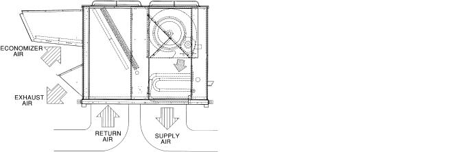
Table 3 — Evaporator Fan Motor Data
UNIT |
UNIT |
|
|
FAN |
|
MOTOR |
|
|
FAN |
|
|
|
|
|
MOTOR |
|
SHEAVE |
BUSHING |
|
SHEAVE |
BUSHING |
|
BELT |
||||
SIZE |
SIZE |
MOTOR |
SHAFT |
MOTOR |
FAN |
BELT |
|||||||
SHAFT DIA. |
PITCH |
DIAMETER |
PITCH |
DIAMETER |
TENSION |
||||||||
48AJ,AK, |
48EJ,EK, |
HP |
(in.) |
SPEED |
SHEAVE |
DIAMETER |
(in.) |
SHEAVE |
DIAMETER |
(in.) |
(Quantity) |
(lb at .25 in.) |
|
AW,AY |
EW,EY |
|
|
(rpm) |
|
(in.) |
|
|
(in.) |
|
|
|
|
|
|
|
|
|
|
|
|
|
|
|
|||
020 |
024 |
5 |
1.125 |
717 |
BK55 |
4.9 |
NONE — 1.125 |
1B5V124 |
12.4 |
B—1.9375 |
BX56 |
8 |
|
10 |
1.375 |
924 |
2BK50 |
4.4 |
NONE — 1.375 |
2B5V86 |
8.6 |
B—1.9375 |
(2) BX50 |
8 |
|||
|
|
15 |
1.625 |
1096 |
2B5V56 |
5.7 |
B — 1.625 |
2B5V90 |
9.1 |
B—1.9375 |
(2) 5VX530 |
9 |
|
025 |
028 |
7.5 |
1.375 |
773 |
BK60H |
5.4 |
H — 1.375 |
1B5V124 |
12.4 |
B—1.9375 |
BX56 |
10 |
|
10 |
1.375 |
962 |
1B5V60 |
6.1 |
H — 1.375 |
1B5V110 |
11.1 |
B—1.9375 |
5VX570 |
11 |
|||
|
|
15 |
1.625 |
1106 |
2B5V54 |
5.5 |
B — 1.625 |
2B5V86 |
8.7 |
B—1.9375 |
(2) 5VX530 |
9 |
|
027 |
030 |
10 |
1.375 |
848 |
2BK50 |
4.4 |
NONE — 1.375 |
2B5V94 |
9.4 |
B—1.9375 |
(2) BX50 |
8 |
|
15 |
1.625 |
1059 |
2B5V48 |
4.9 |
B — 1.625 |
2B5V80 |
8.1 |
B—1.9375 |
(2) 5VX500 |
10 |
|||
|
|
20 |
1.625 |
1187 |
2B5V58 |
5.9 |
B — 1.625 |
2B5V86 |
8.7 |
B—1.9375 |
(2) 5VX530 |
11 |
|
030 |
034 |
10 |
1.375 |
884 |
2BK50 |
4.4 |
H — 1.375 |
2B5V90 |
9.0 |
B—1.9375 |
(2) BX50 |
8 |
|
15 |
1.625 |
1096 |
2B5V56 |
5.7 |
B — 1.625 |
2B5V90 |
9.1 |
B—1.9375 |
(2) 5VX530 |
9 |
|||
|
|
20 |
1.625 |
1187 |
2B5V58 |
5.9 |
B — 1.625 |
2B5V86 |
8.7 |
B—1.9375 |
(2) 5VX530 |
11 |
|
035 |
038 |
10 |
1.375 |
779 |
1B5V60 |
6.1 |
NONE — 1.375 |
1B5V136 |
13.7 |
B—1.9375 |
5VX610 |
12 |
|
15 |
1.625 |
976 |
2B5V52 |
5.3 |
B — 1.625 |
2B5V94 |
9.5 |
B—1.9375 |
(2) 5VX530 |
10 |
|||
|
|
20 |
1.625 |
1050 |
2B5V56 |
5.7 |
B — 1.625 |
2B5V94 |
9.5 |
B—1.9375 |
(2) 5VX550 |
11 |
|
040 |
044 |
15 |
1.625 |
976 |
2B5V52 |
5.3 |
B — 1.625 |
2B5V94 |
9.5 |
B—1.9375 |
(2) 5VX530 |
10 |
|
20 |
1.625 |
1050 |
2B5V56 |
5.7 |
B — 1.625 |
2B5V94 |
9.5 |
B—1.9375 |
(2) 5VX550 |
11 |
|||
|
|
25 |
1.875 |
1182 |
2B5V74 |
7.5 |
B — 1.875 |
2B5V110 |
11.1 |
B—1.9375 |
(2) 5VX590 |
11 |
|
050 |
048 |
20 |
1.625 |
993 |
2B5V62 |
6.3 |
B — 1.625 |
2B5V110 |
11.1 |
B—1.9375 |
(2) 5VX570 |
11 |
|
25 |
1.875 |
1134 |
2B5V80 |
8.1 |
B — 1.875 |
2B5V124 |
12.5 |
B—1.9375 |
(2) 5VX630 |
11 |
|||
|
|
30 |
1.875 |
1182 |
2B5V74 |
7.5 |
B — 1.875 |
2B5V110 |
11.1 |
B—1.9375 |
(2) 5VX590 |
13 |
|
— |
054 |
15 |
1.625 |
741 |
2B5V46 |
4.7 |
B — 1.625 |
2B5V110 |
11.1 |
B—1.9375 |
(2) 5VX550 |
11 |
|
20 |
1.625 |
962 |
2B5V60 |
6.1 |
B — 1.625 |
2B5V110 |
11.1 |
B—1.9375 |
(2) 5VX570 |
12 |
|||
|
|
25 |
1.875 |
1134 |
2B5V80 |
8.1 |
B — 1.875 |
2B5V124 |
12.5 |
B—1.9375 |
(2) 5VX630 |
12 |
|
— |
058 |
20 |
1.625 |
930 |
2B5V58 |
5.9 |
B — 1.625 |
2B5V110 |
11.1 |
B—1.9375 |
(2) 5VX570 |
13 |
|
25 |
1.875 |
1056 |
2B5V66 |
6.7 |
B — 1.875 |
2B5V110 |
11.1 |
B—1.9375 |
(2) 5VX590 |
14 |
|||
|
|
30 |
1.875 |
1182 |
2B5V74 |
7.5 |
B — 1.875 |
2B5V110 |
11.1 |
B—1.9375 |
(2) 5VX590 |
14 |
|
060 |
064 |
25 |
1.875 |
1019 |
3B5V52 |
5.3 |
B — 1.875 |
3B5V90 |
9.1 |
B—1.9375 |
(3) 5VX530 |
12 |
|
30 |
1.875 |
1134 |
2B5V80 |
8.1 |
B — 1.875 |
2B5V124 |
12.5 |
B—1.9375 |
(2) 5VX630 |
14 |
|||
|
|
40 |
2.125 |
1214 |
2B5V94 |
9.4 |
B — 2.125 |
2B5V136 |
13.6 |
B—1.9375 |
(2) 5VX650 |
15 |
|
— |
068 |
25 |
1.875 |
938 |
2B5V66 |
6.7 |
B — 1.875 |
2B5V124 |
12.5 |
B—1.9375 |
(2) 5VX610 |
14 |
|
30 |
1.875 |
1087 |
3B5V58 |
5.9 |
B — 1.875 |
3B5V94 |
9.5 |
B—1.9375 |
(3) 5VX550 |
13 |
|||
|
|
40 |
2.125 |
1214 |
2B5V94 |
9.4 |
B — 2.125 |
2B5V136 |
13.6 |
B—1.9375 |
(2) 5VX650 |
15 |
NOTES:
1. |
Motor shaft speed is 1750 rpm. The fan shaft diameter is 115/16 inches. |
2. |
All indoor fan motors meet the minimum efficiency requirements |
|
as established by the Energy Policy Act of 1992 (EPACT), effective |
|
October 24, 1997. |
Fig. 18 — Air Distribution — Thru-the-Bottom |
Fig. 19 — Air Distribution — Thru-the-Side |
27
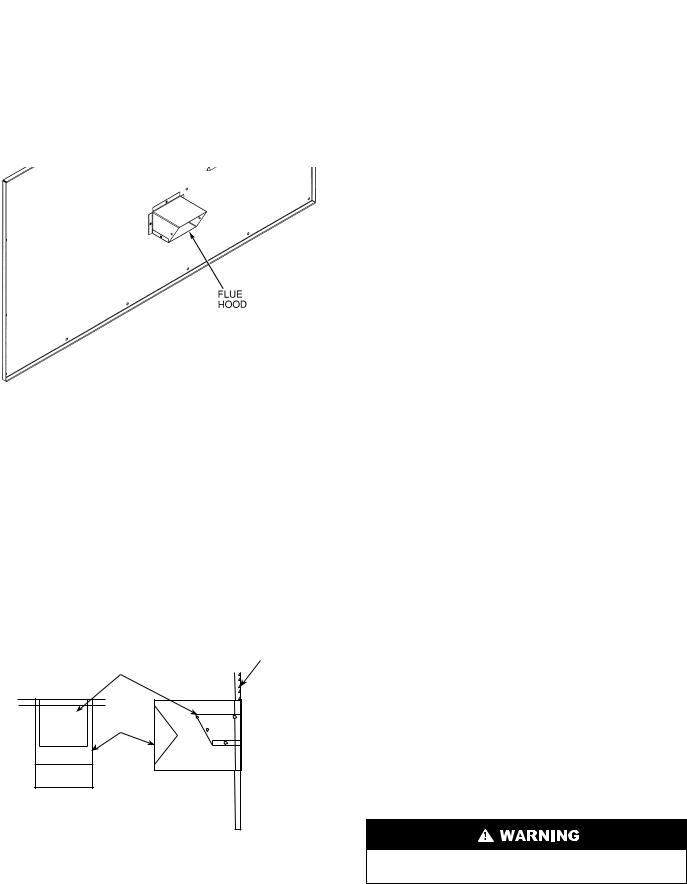
Step 5 — Install Flue Hood
48AJ,AK,AW,AY020-050 AND 48EJ,EK,EW,EY024-048 UNITS — Flue hood is shipped inside gas section of unit. To install, secure flue hood to access panel. See Fig. 20A.
48AJ,AK,AW,AY060 AND 48EJ,EK,EW,EY054-068 UNITS — Flue hood and wind baffle are shipped inside gas section of unit. To install, secure flue hood to access panel. Install the two pieces of the wind baffle over the flue hood. See Fig. 20B.
NOTE: When properly installed, flue hood will line up with combustion fan housing. See Fig. 21.
Fig. 21 — Combustion Fan Housing Location
Step 6 — Trap Condensate Drain — See Fig. 5-16 for drain location. Condensate drain is open to atmosphere and must be trapped. Install a trapped drain at the drain location. One 1-in. FPT coupling is provided inside the unit evaporator section for condensate drain connection. A trap at least 4-in. deep must be used. See Fig. 22. Trap must be installed to prevent freeze-up.
Condensate pans are sloped so that water will completely drain from the condensate pan to comply with indoor air quality guidelines. The condensate drain pans are not insulated.
Fig. 20A — Flue Hood Location (48AJ,AK,AW,AY020-050 and 48EJ,EK,EW,EY024-048 Units)
GAS SECTION
ACCESS PANEL
FLUE HOOD
WIND
BAFFLE
TOP VIEW |
SIDE VIEW |
Fig. 20B — Flue Hood Location (48AJ,AK,AW,AY060 and 48EJ,EK,EW,EY054-068 Units)
Fig. 22 — Condensate Drain Trap Piping Details (Typical Roof Curb or Slab Mount Shown)
Step 7 — Install Gas Piping — Unit is equipped for use with natural gas. Installation must conform with local building codes or, in the absence of local codes, with the National Fuel Gas Code, ANSI Z223.1.
Install manual gas shutoff valve with a 1/8-in. NPT pressure tap for test gage connection at unit. Field gas piping must include sediment trap and union. See Fig. 23. An 1/8-in. NPT is also located on the gas manifold adjacent to the gas valve.
Do not pressure test gas supply while connected to unit. Always disconnect union before servicing.
28
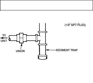
IMPORTANT: Natural gas pressure at unit gas connection must not be less than 5 in. wg or greater than 13.5 in. wg.
Size gas-supply piping for 0.5-in. wg maximum pressure drop. Do not use supply pipe smaller than unit gas connection.
Fig. 23 — Field Gas Piping
OPTIONAL STAGED GAS UNITS — The staging pattern is selected based on Heat Stage Type (HTSTGTYP). Max Capacity per changes default value is selected based on Capacity Maximum Stage (CAPMXSTG). See Table 4.
For complete information and service instructions for Staged Gas Control Units, see Control Operation and Troubleshooting literature.
Step 8 — Controls Options — The control options that the units can provide are based on the following parameters: CV (constant volume) or VAV (variable air volume) operation; stand-alone unit with field-supplied sensors installed (CV or VAV); as a system via Carrier Comfort System (TEMP or VVT® [Variable Volume and Temperature]); optional electronic expansion board installed (CV or VAV); linked to the Carrier Comfort Network; availability of a computer and software (ComfortWORKS® Building Supervisor, and Service Tool) or remote enhanced display accessory installed to access the base control board; and optional factory-installed staged gas control. See Table 5.
NOTE: Access to the base control board allows unit occupancy schedules, unit timeclock, and various set points to be changed from their factory-defined default settings.
Table 4 — 48A,E Series Staged Gas Implementation
NUMBER OF STAGES |
|
MODEL NUMBER POSITION |
POSITION |
HEAT SIZE |
|||
3 |
|
5 |
6,7,8 |
HTSTGTYP |
CAPMXSTG |
||
|
|
|
|||||
|
|
|
|
024 |
|
|
|
|
|
|
|
028 |
|
|
|
|
|
|
|
030 |
|
|
|
|
E |
|
S |
034 |
Default=1 |
Default=20 |
Low |
|
|
|
|
038 |
|
|
|
|
|
|
|
044 |
|
|
|
|
|
|
|
048 |
|
|
|
|
|
|
|
020 |
|
|
|
|
|
|
|
025 |
|
|
|
5 stages |
|
|
|
027 |
|
|
|
A |
|
S |
030 |
Default=1 |
Default=20 |
Low |
|
|
|
|
|
035 |
|
|
|
|
|
|
|
040 |
|
|
|
|
|
|
|
050 |
|
|
|
|
|
|
|
038 |
|
|
|
|
E |
|
T |
044 |
Default=1 |
Default=20 |
High |
|
|
|
|
048 |
|
|
|
|
|
|
|
035 |
|
|
|
|
A |
|
T |
040 |
Default=1 |
Default=20 |
High |
|
|
|
|
050 |
|
|
|
|
|
|
|
024 |
|
|
|
|
E |
|
T |
028 |
Default=2 |
Default=15 |
High |
|
|
030 |
|||||
|
|
|
|
|
|
|
|
7 stages |
|
|
|
034 |
|
|
|
|
|
|
020 |
|
|
|
|
|
|
|
|
|
|
|
|
|
A |
|
T |
025 |
Default=2 |
Default=15 |
High |
|
|
027 |
|||||
|
|
|
|
|
|
|
|
|
|
|
|
030 |
|
|
|
|
|
|
|
054 |
|
|
|
|
E |
|
T |
058 |
Default=3 |
Default=15 |
High |
9 stages |
|
064 |
|||||
|
|
|
|
|
|
||
|
|
|
|
068 |
|
|
|
|
A |
|
T |
060 |
Default=3 |
Default=15 |
High |
|
|
|
|
054 |
|
|
|
|
E |
|
S |
058 |
Default=4 |
Default=15 |
Low |
11 stages |
|
064 |
|||||
|
|
|
|
|
|
||
|
|
|
|
068 |
|
|
|
|
A |
|
S |
060 |
Default=4 |
Default=15 |
Low |
29
Table 5 — Controls Options and Configurations (Non-Thermostat Applications)
|
UNIT CONFIGURATION |
DEFAULT COOLING |
DEFAULT HEATING |
|
CV or VAV Unit with SPT Sensor |
Unoccupied Cooling — 90 F (32 C) (SPT) |
Unoccupied Heating — 55 F (13 C) (SPT) |
||
Occupied Cooling — NA |
Occupied Heating — NA |
|||
|
|
|||
CV Unit with SPT Sensor and Remote |
Unoccupied Cooling — 90 F (32 C) (SPT) |
Unoccupied Heating — 55 F (13 C) (SPT) |
||
Start/Stop Switch |
Occupied Cooling — 78 F (26 C) (SPT) |
Occupied Heating — 68 F (20 C) (SPT) |
||
VAV Unit Remote Start/Stop Switch Only |
Unoccupied Cooling — 90 F (32 C)(SPT) |
Unoccupied Heating — 55 F (13 C) (RAT) |
||
Occupied Cooling — 55 F (13 C) SPT) |
Occupied Heating — 68 F (20 C) (RAT)* |
|||
|
|
|||
VAV Unit with SPT Sensor and Remote |
Unoccupied Cooling — 90 F (32 C) (SPT) |
Unoccupied Heating — 55 F (13C) (SPT) |
||
Start/Stop Switch |
Occupied Cooling — 55 F (13 C) (SAT) |
Occupied Heating — 68 F (20 C) (RAT)* |
||
|
LEGEND |
|
|
|
CV |
— Constant Volume |
|
|
|
NA |
— Not Available |
|
|
|
RAT — Return-Air Temperature |
|
|
||
SAT — Supply-Air Temperature |
|
|
||
SPT |
Space Temperature |
|
|
|
VAV |
— Variable Air Volume |
|
|
|
*With DIP Switch No. 5 configured to OPEN (Occupied Heat Enabled).
NOTE: Space temperature sensor and remote start/stop switch are field-supplied.
STAGED GAS UNIT APPLICATIONS — The rooftop units may be ordered with an optional factory-installed staged gas control system that monitors heating operation of the rooftop unit.
IMPORTANT: An accessory field-supplied Navigator display module is required for all staged gas control units.
Install Supply-Air Thermistors (Staged Gas Units Only) — Supply-air thermistors are a field-installed factory-provided component. Three supply-air thermistors are shipped with staged gas units and are inside the heating section. Thermistor wires must be connected to SGC (staged gas controller) in the heating section. See Table 6 and Fig 24. The supply-air thermistors should be located in the supply duct with the following criteria:
•downstream of the heat exchanger cells
•equally spaced as far as possible from the heat exchanger cells
•a duct location where none of the supply air thermistors are within sight of the heat exchanger cells
•a duct location with good mixed supply air portion of the unit.
THERMISTORS — All units are equipped with a supply air thermistor (SAT) located in the supply fan discharge and an outdoor air thermistor (OAT) located in the outdoor air hood. Variable air volume (VAV) units are supplied with a return air thermistor (RAT) located on the return air damper support.
CONSTANT VOLUME APPLICATIONS — The units, as shipped, are operable as stand-alone units, using either a standard (mechanical or electronic) 2-stage heat, 2-stage cool thermostat, or with an electronic room sensor and a timeclock to establish unit start and stop times.
With a standard thermostat (programmable is optional), heating and cooling operation is set by space temperature.
With a space sensor and timeclock, the machine will operate at default values unless they are changed using appropriate input devices. The space sensor senses space temperature and may be equipped with a timed override feature, which allows unit operation during unoccupied periods.
The space sensors may be used in multiples of 4 or 9 to achieve space temperature averaging. The use of a space sensor also allows the unit to be turned on and off from a remote signal.
|
|
Table 6 — Thermistor Designations |
|
|
|
|
|
|
|
|
PIN |
FUNCTION AND LOCATION |
|
|
THERMISTOR |
CONNECTION |
|
PART NO. |
|
Thermistors |
||||
|
POINT |
|
||
|
|
|
||
SAT 1 |
J8 – 1,2 (SGC) |
Supply Air Thermistor (SAT) — Inserted into supply section |
|
|
underneath the gas heat section (factory-provided, field-installed) |
|
|||
|
|
|
||
SAT 2 |
J8 – 3,4 (SGC) |
Supply Air Thermistor (SAT) — Inserted into supply section |
HH79NZ016 |
|
underneath the gas heat section (factory-provided, field-installed) |
||||
|
|
|
||
SAT 3 |
J8 – 5,6 (SGC) |
Supply Air Thermistor (SAT) — Inserted into supply section |
|
|
underneath the gas heat section (factory-provided, field-installed) |
|
|||
|
|
|
30
 Loading...