

Page 1
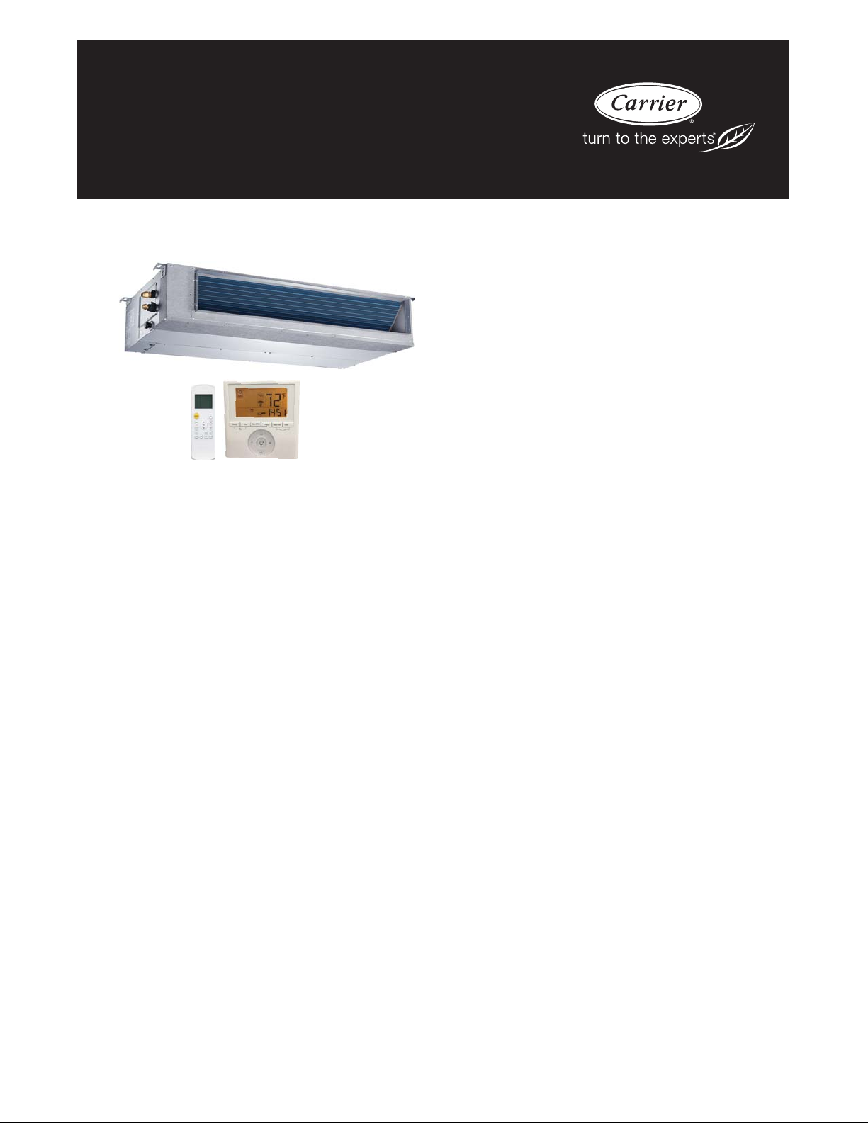
40MBDQ
Ducted Style Ductless System
Sizes 18 to 48
Product Data
NOTE: Images for illustration purposes only. Actual models may
be slightly different.
INDUSTRY LEADING FEATURES / BENEFITS
A PERFECT BALANCE BETWEEN
BUDGET LIMITS, ENERGY SAVINGS AND
COMFORT.
The 40MBDQ series ducted style ductless systems are a matched
combination of an outdoor condensing unit and an indoor fan coil
unit connected only by refrigerant tubing and wires.
The fan coil is mounted in the ceiling. This selection of fan coils
permits creative solutions to design problems such as:
S Add−ons to current space (an office or family room
addition)
S Special space requirements
S When changes in the load cannot be handled by the
existing system.
S Historical renovations or any application where
preserving the look of the original structure is essential.
These compact indoor fan coil units take up very little space above
the ceiling. Advanced system components incorporate innovative
technology to provide reliable cooling performance at low sound
levels.
Page 2

LOW SOUND LEVELS
When noise is a concern, the ductless split systems are the answer.
The indoor units are whisper quiet. There are no compressors
indoors, either in the conditioned space or directly over it, and
there is none of the noise usually generated by air being forced
through ductwork.
SECURE OPERATION
If security is an issue, outdoor and indoor units are connected only
by refrigerant piping and wiring to prevent intruders from
crawling through ductwork. In addition, since outdoor units can
be installed close to an outside wall, coils are protected from
vandals and severe weather.
FAST INSTALLATION
This compact ductless system is simple to install. A mounting
bracket and duct work is needed for the indoor units, and only
wire and piping need run between the indoor and outdoor units.
These units are fast and easy to install ensuring minimal
disruption to customers in the home or workplace. This makes the
ducted style ductless systems the equipment of choice, especially
in retrofit situations.
BUILT−IN RELIABILITY
Ducted style ductless system indoor and outdoor units are designed
to provide years of trouble−free operation.
The ducted indoor units include protection against freeze−up and
high evaporator temperatures on heat pumps.
The condensing units on heat pumps are protected by a three
minute time delay before the compressor starts the over−current
protection and the high temperature protection.
INDIVIDUAL ROOM COMFORT
Maximum comfort is provided because each space can be
controlled individually based on usage pattern. The air sweep
feature provided permits optimal room air mixing to eliminate hot
and cold spots for occupant comfort. In addition, year−round
comfort can be provided with heat pumps.
ECONOMICAL OPERATION
The ducted style ductless system design allows individual or
multi−room heating or cooling when required. There is no need to
run large supply−air fans or chilled water pumps to handle a few
spaces with unique load patterns.
SIMPLE SERVICING AND M A INTENANCE
Removing the top panel on outdoor units provides immediate
access to the control compartment, providing a service technician
access to check unit operation. In addition, the draw−thru design of
the outdoor section means that dirt accumulates on the outside
surface of the coil. Coils can be cleaned quickly from the inside
using a pressure hose and detergent.
On all indoor units, service and maintenance expense is reduced
due to easy accessible service panels. In addition, these ducted
systems have extensive self−diagnostics to assist in
troubleshooting.
EASY−TO−USE CONTROLS
The ducted units have microprocessor−based controls to provide
the ultimate in comfort and efficiency. The user friendly wired and
wireless remote control provides the interface between user and
the unit.
BUILT−IN CONDENSATE LIFT PUMP
Factory installed condensate lift pump on the ducted fan coil
provides installation flexibility.
OPTIONAL WIRED CONTROLLER
Timer Function
STANDARD WIRED CONTROLLER
7 Day Programmable
AGENCY LISTINGS
All systems are listed with AHRI (Air Conditioning, Heating &
Refrigeration Institute), and ETL.
2
Page 3
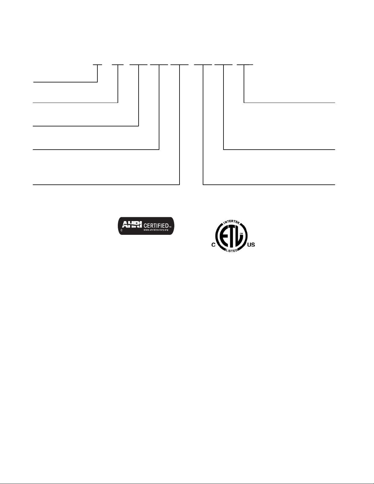
MODEL NUMBER NOMENCLATURE
INDOOR UNIT
QD-
40 = FAN COIL UNIT
MB = MODEL
INDOOR FAN COIL TYPE
D = DUCTED STYLE
40 MB 309
- -
VOLTAGE
3 = 208/230-1-60
SYSTEM TYPE
Q = HEAT PUMP
NOMINAL CAPACITY
18 - 1-1/2 TONS
24 - 2 TONS
36 - 3 TONS
48 - 4 TONS
Use of the AHRI Certified
TM Mark indicates a
manufacturer’s
participation in the
program For verification
of certification for individual
products, go to
www.ahridirectory.org.
NOT USED
NOT USED
3
Page 4

STANDARD FEATURES AND ACCESSORIES
Ease Of Installation
Mounting Brackets S
Low Voltage Controls S
Comfort Features
Rear or Bottom Return S
Microprocessor Controls S
Wired Remote Control (7 Day Programmable
KSACN0501AAA
Wireless Remote Control S
Auto Restart Function S
Cold Blow Protection On Heat Pumps S
Freeze Protection Mode On Heat Pumps S
Turbo Mode S
Auto Changeover On Heat Pumps S
Follow Me (Sense Temperature at remote) S
Energy Saving Features
Outside Air Intake S
Sleep Mode S
Stop/Start Timer S
46°F Heating Mode (Heating Setback)
Safety And Reliability
Indoor Coil Freeze Protection S
Indoor Coil High Temp Protection in Heating Mode S
Aluminum Blue Hydrophilic pre-coated fins S
Ease Of Service And Maintenance
Cleanable Filters S
Diagnostics S
Liquid Line Pressure Taps S
Application Flexibility
Built-in Condensate Lift Pump S
Legend
S Standard
A Accessory
S
S
4
Page 5
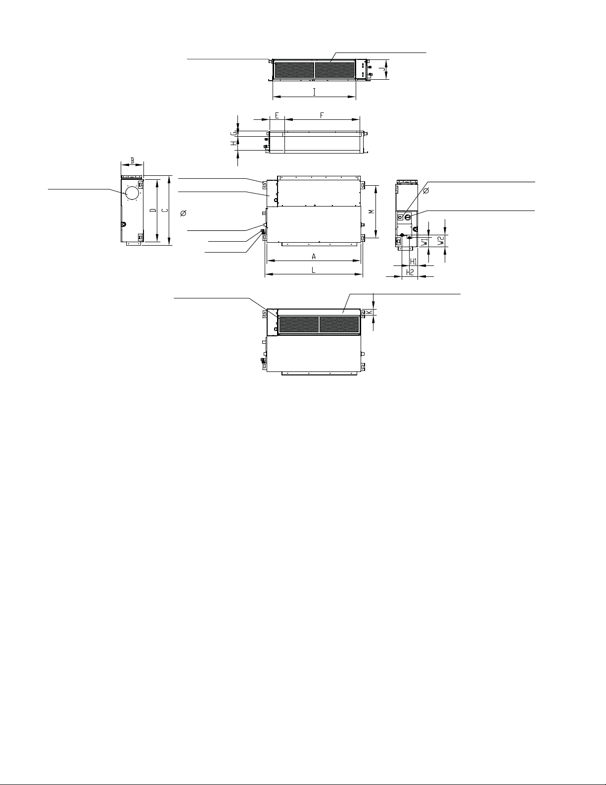
DIMENSIONS − INDOOR
Air filter
Air inlet from rear side
Outside air intake
4-install hanger
Electric control box
Test mouth & Test cover
0.98in (25mm) Drain
connecting pipe (for lift pump)
0.98in (25mm)
Drain pipe
Gas connection
Liquid connection
Air filter
Fig. 1 – Indoor Unit
OUTLINE
DIMENSIONS
Size Unit A B C D E F G H I J K L M H1 H2 W1 W2
In. 34.65 8.27 26.54 23.62 5.51 27.80 1.97 5.35 30.79 7.48 1.57 36.22 20 3.07 5.83 3.46 4.41 54
18
mm 880 210 674 600 140 706 50 136 782 190 40 920 508 78 148 88 112 24.5
In. 43.31 9.8 30.47 27.56 5.51 36.46 1.97 6.89 39.41 8.98 0.2 44.88 23.54 3.15 5.91 5.12 6.1 87
24
mm 1100 249 774 700 140 926 50 175 1001 228 5 1140 598 80 150 130 155 39.4
In. 53.54 9.8 30.47 27.56 5.51 46.69 1.97 6.89 49.65 8.98 0.2 55.12 23.54 3.15 5.91 5.12 6.1 106
36
mm 1360 249 774 700 140 1186 50 175 1261 228 5 1400 598 80 150 130 155 48.3
In. 47.24 11.81 34.41 31.5 4.84 41.1 1.97 8.94 43.35 11.02 0.2 48.82 27.44 3.15 5.91 7.28 8.27 120
48
mm 1200 300 874 800 123 1044 50 227 1101 280 5 1240 697 80 150 185 210 54.3
AIR OUTL ET
OPENING SIZE
AIR RETURN
OPENING SIZE
Air inlet from bottom side
HANGER
BRACKERS
REFRIGERANT PIPE
LOCATIONS
OPERATING
WEIGHT
lb (kg)
5
Page 6
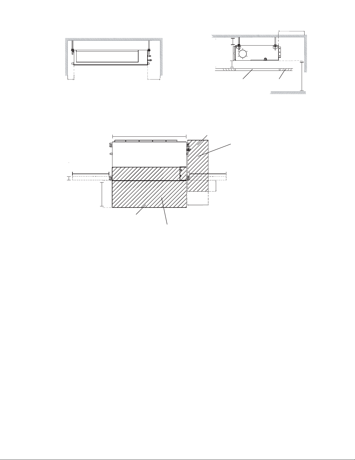
CLEARANCES − INDOOR
Strong and durable ceiling
Indoor unit
Left
side
Right
side
>0.8in(2cm)
>
0.8in(2cm)
>
11.8in(30cm)
>4in(10cm) >11.8in(30cm)
Maintenance space
MAINTENANCE CLEARANCES
Filter service clearance
(only one side is required)
A/2
>0.4in(1cm)
)
>11.8in(30cm
Service access
Fig. 2 – Installation Clearances
A
Service access
Unit
>11.8in(30cm)
BLOWER/MOTOR SERVICE CLEARANCE
PCB BOARD SERVICE CLEARANCE
FILTER SERVICE CLEARANCE
Service access Ceiling
COIL CONNECTION AREA
CONDENSATE DRAIN PIPING AREA
CONDENSATE PUMP SERVICE CLEARANCE
SENSOR SERVICE CLEARANCE
A/2
>4in(10cm)
Floor
> 8.2in(250cm)
(When no ceiling)
Fig. 3 – Maintenance Clearances
Capacity (Kbtu) A B
18K 36.22in.(92cm) 11.81in.(30cm)
24K 36.22in.(92cm) 11.81in.(30cm)
36K 44.88in.(114cm) 11.81in.(30cm)
48K 47.24in.(120cm) 15.75in.(40cm)
6
Page 7

SPECIFICATIONS
System
Electrical
Controls
Operating
Range
Piping
Indoor
Size 18 24 36 48
Indoor Model 40MBDQ18---3 40MBDQ24---3 40MBDQ36---3 40MBDQ48---3
Voltage, Phase, Cycle V/Ph/Hz 208/230-1-60 208/230-1-60 208/230-1-60 208/230-1-60
Power Supply Indoor unit powered from outdoor unit
MCA A. 1.2 1.2 2.45 3.2
Wireless Remote
Controller
(°F/°C Convertible)
Wired Remote Controller
(°F/°C Convertible)
Cooling Indoor DB
Min -Max
Heating Indoor DB
Min -Max
Pipe Connection
Size - Liquid
Pipe Connection
Size - Suction
Unit Width in (mm) 34.65 (880) 43.31 (1100) 53.54 (1360) 47.24 (1200)
Unit Height in (mm) 8.27 (210) 9.8 (249) 9.8 (249) 11.81 (300)
Unit Depth in (mm) 26.54 (674) 30.47 (774) 30.47 (774) 34.41 (874)
Net Weight lbs (kg) 54 (24.5) 86.86 (39.4) 106.48 (48.3) 119.71 (54.3)
Number of Fan Speeds 3 3 3 3
Airflow
(lowest to highest)
Sound Pressure
(lowest to highest)
Max Static Pressure In.WG. 0.40 0.64 0.64 0.64
Field Drain Pipe Size
O.D.
Heat Pump
Standard Standard Standard Standard
Standard Standard Standard Standard
° F (° C) 63~90 (17~32) 63~90 (17~32) 63~90 (17~32) 63~90 (17~32)
° F (° C) 32~86 (0~30) 32~86 (0~30) 32~86 (0~30) 32~86 (0~30)
in (mm) 1/4 (6.35) 3/8 (9.52) 3/8 (9.52) 3/8 (9.52)
in (mm) 1/2 (12.7) 5/8 (16) 5/8 (16) 5/8 (16)
CFM 300/400/480 440/700/780 700/910/1080 720/1030/1230
dB(A) 35/37/39 35.5/40/44 38.5/42/45.5 46/49.5/50.5
in (mm) 1 (25.4) 1 (25.4) 1 (25.4) 1 (25.4)
Performance may vary based on the outdoor unit matched to. See the compatible outdoor units product data for Performance Data.
COMPATIBILITY TABLE
Indoor Unit 40MBDQ18---3 40MBDQ24---3 40MBDQ36---3 40MBDQ48---3
Outdoor Unit Single Zone 38MAQB18R--3 38MAQB24R--3 38MBRQ36A--3 38MBRQ48A--3
38MGRQ24C--3
Outdoor Unit Multi-zone
NOTE: Backward compatible with Single Zone Systems 38MAQ sizes 09−24, 38MBQ Sizes 36−48 and Multi−zone Systems 38MGQ.
38MGRQ30D--3
38MGRQ36D--3
38MGRQ48E--3
7
Page 8
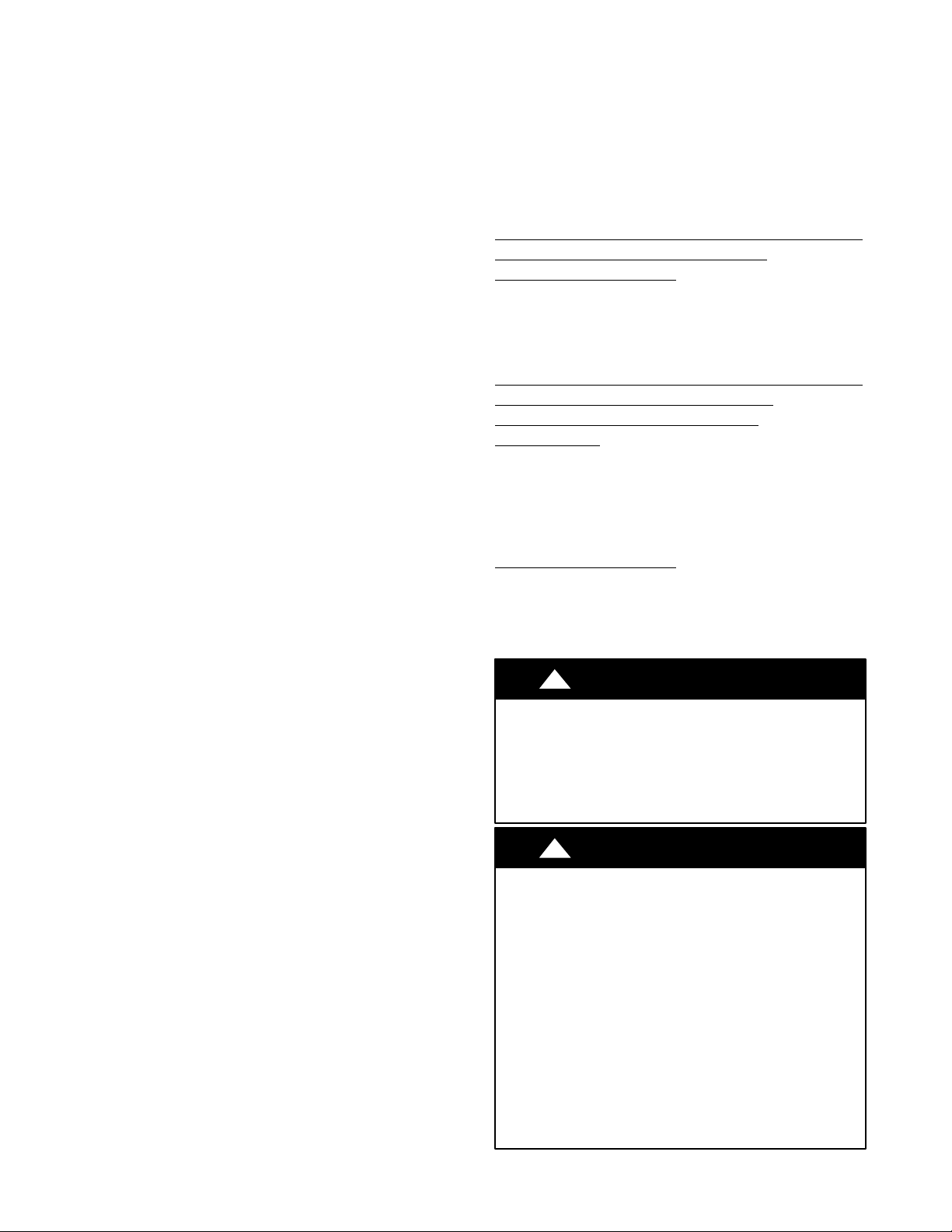
APPLICATION DATA
UNIT SELECTION
Select equipment to either match or that can handle slightly less
than the anticipated peak load. This provides better humidity
control, fewer unit cycles, and less part−load operation.
For units used in spaces with high sensible loads, base equipment
selection on unit sensible load, not on a total anticipated load.
Adjust for anticipated room wet bulb temperature to avoid
undersizing equipment.
UNIT MOUNTING (INDOOR)
Refer to unit Installation Instructions for further details.
Unit leveling − For reliable operation, units should be level in all
planes.
Clearance − Provide adequate clearance for airflow as shown in
Fig. 3.
Unit location − Select a location which provides the best air
circulation for the room.
These units should be positioned as accessible as possible above
the ceiling. The unit return and discharge should not be obstructed
by furniture, curtains, or anything which may cause unit short
cycling or air recirculation. Duct the unit in the middle of the
selected wall (if possible). Duct towards an outside wall, if
available, to make piping easier, and place the unit so it faces the
normal location of room occupants.
UNIT MOUNTING (OUTDOOR)
Refer to unit Installation Instructions for further details.
Do not install the indoor or outdoor units in a location with special
environmental conditions. For those applications, contact your
ductless representative.
MOUNTING
Refer to unit’s Installation Instructions for further details.
SUPPORT
Adequate support must be provided to support the weight of all fan
coils. Refer to the Physical Data section for fan coil weights, and
the base unit dimensional drawings for the location of mounting
brackets.
SYSTEM OPERATING CONDITIONS
OPERATING RANGE
Min / Max °F (°C)
Cooling Heating
Indoor DB 63 / 90 (17 / 32) 32 / 86 (0 / 30)
Indoor WB 59 / 84 (15 / 29)
NOTE: Reference the product Installation Instructions for more
information.
DRAIN CONNECTIONS
Install drains to meet local sanitation codes. The standard ducted
fan coil unit condensate lift pump has a maximum lift of 29.5 in.
(750mm).
WIRING
All wires must be sized per NEC (National Electrical Code) or
CEC (Canadian Electrical Code) and local codes. Use the Electrical
Data table MCA (minimum circuit amps) and MOCP (maximum
over current protection) to correctly size the wires and the
disconnect fuse or breakers respectively. Per the caution note, only
Stranded copper conductors with a 600 volt rating and double
insulated copper wire must be used.
NOTE: The use of BX cable is not recommended.
Recommended Connection Method for Power and
Communication Wiring − Power and
Communication Wiring:
The main power is supplied to the outdoor unit. The field supplied
14/3 power/communication wiring from the outdoor unit to the
indoor unit consists of four (4) wires and provides the power for
the indoor unit. Two wires are high voltage AC power, one is
communication wiring and the other is a ground wire.
Recommended Connection Method for Power and
Communication Wiring (To minimize
communication wiring interference)
PowerWiring:
The main power is supplied to the outdoor unit. The field supplied
power wiring from the outdoor unit to the indoor unit consists of
three (3) wires and provides the power for the indoor unit. Two
wires are high voltage AC power and one is a ground wire. To
minimize voltage drop, the factory recommended wire size is 14/2
stranded with a ground.
Communication Wiring:
A separate shielded stranded copper conductor only, with a
minimum 600 volt rating and double insulated copper wire, must
be used as the communication wire from the outdoor unit to the
indoor unit. Please use a separate shielded 16GA stranded control
wire.
!
EQUIPMENT DAMAGE HAZARD
Failure to follow this caution may result in equipment
damage or improper operation.
S Wires should be sized based on NEC and local codes.
S Use copper conductors only with a 600 volt rating and
double insulated copper wire.
!
EQUIPMENT DAMAGE HAZARD
Failure to follow this caution may result in equipment
damage or improper operation.
S Be sure to comply with local codes while running wire
from indoor unit to outdoor unit.
S Every wire must be connected firmly. Loose wiring
may cause terminal to overheat or result in unit
malfunction. A fire hazard may also exist. Therefore,
be sure all wiring is tightly connected.
S No wire should be allowed to touch refrigerant tubing,
compressor or any moving parts.
S Disconnecting means must be provided and shall be
located within sight and readily accessible from the air
conditioner.
S Connecting cable with conduit shall be routed through
hole in the conduit panel.
CAUTION
CAUTION
8
Page 9
CONTROL SYSTEM
The indoor unit is equipped with a microprocessor control to
perform two functions:
1. Provide safety for the system
2. Control the system and provide optimum levels of comfort
and efficiency
The main microprocessor is located on the control board of the
fan coil unit (outdoor units have a microprocessor also) with
thermistors located in the fan coil air inlet and on the indoor coil.
Heat pump units have a thermistor on the outdoor coil. These
thermistors monitor the system operation to maintain the unit
within acceptable parameters and control the operating mode.
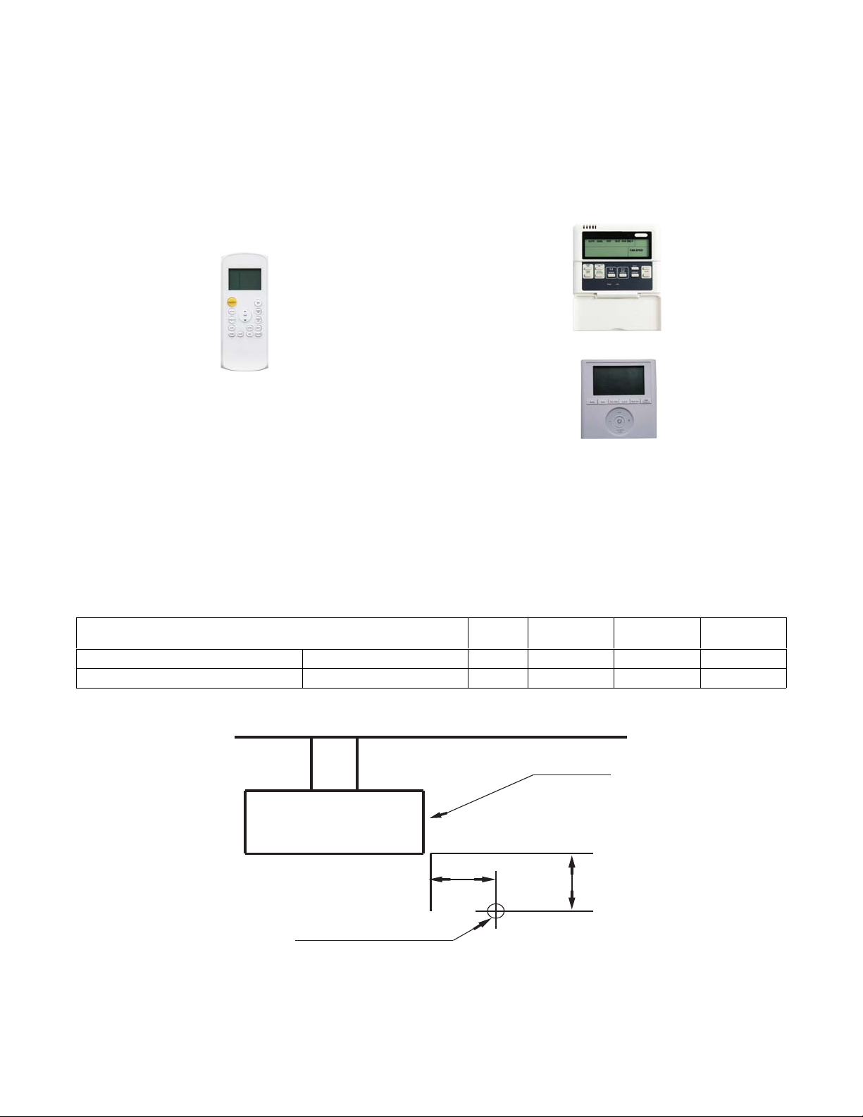
WIRELESS REMOTE CONTROL
Fig. 4 – Wireless Remote Control
1. A wireless remote control is supplied for system operation
for system operation of all ducted units.
2. Each battery operated wireless (infrared) remote control
may be used to control more than one unit.
WIRED REMOTE CONTROL
P/N KSACN0101AAA (optional available as an accessory)
P/N KSACN0501AAA (included with the Unit)
1. Wired remote controller used for system operation of all
ducted units.
2. Kit includes a wired remote controller and a connecting
cable.
3. Connect with wire terminal between remote controller and
indoor unit.
4. Display in _F or _C and temperature increments every 1_F
or every 1_C.
Fig. 5 – KSACN0101AAA (Timer Function)
Fig. 6 – KSACN0501AAA (7 Day Programmable)
AIR FLOW DATA
System Size 18K 24K 36K 48K
High 480 780 1080 1230
Indoor (CFM)
Medium 400 700 910 1030
Low 300 440 700 720
SOUND PRESSURE
System Size
Cooling operation Indoor Sound Pressure dBa at (High / Med /Low CFM) 39/37/35 44/40/35.5 45.5/42/38.5 50.5/49.5/46
Heating operation Indoor Sound Pressure dBa at (High / Med /Low CFM) 37/36/34 41.9/39.2/36.7 45.4/43/39.4 50.1/48.5/45.3
18K
(208/230V)
24K
(208/230V)
36K
(208/230V)
48K
(208/230V)
SOUND PRESSURE TESTING METHOD
Unit Outlet
Indoor Unit
3.2 ft (1m)
x
Microphone
Fig. 7 – Sound Pressure Testing Method
9
3.2 ft (1m)
Page 10

SOUND POWER
System Size 18K 24K 36K 48K
Cooling operation Indoor Sound Power dBa (H) 64 66.9 62 70.4
Heating operation Indoor Sound Power dBa (H) 48 58 61 55
FAN AND MOTOR SPECIFICATIONS
Ducted size
material Metal Metal Metal Metal
Type LFLBJ-150*158*12-41 FLBJ-200*198*12-46 FLBJ-200*266*12.7-46 FLBJ-230*264*12.7-40
Diameter inch 6.06 inch 7.87 inch 7.87 inch 9.06 inch
Indoor fan
Height inch 6.22 inch 7.80 inch 10.47 inch 10.39 inch
Model ZKFN-160-8-1-2 ZKFN-160-8-1-2 ZKFN-300-8-1 ZKFN-560-8-1-1
Volts V 208/230 208/230 208/230 208/230
Type DC DC DC DC
Phase 3 3 3 3
FLA 1.65 1.65 2.45 4.1
Insulation class E E E E
Safe class IPX0 IPX0 IPX0 IPX0
Input W 200 200 420 560
Output W 160 160 300 560
Range of
current
Indoor fan motor
Rated
current
Rated HP HP 0.27 0.27 0.56 0.75
Speed rev/min 850/700/450 880/820/690 1130/1050/990 890/820/840
Rated
RPM
Max.
input
Amps 1.2±10% 1.2±10% 2.45±10% 3.2±10%
Amps 1.2 1.2 2.45 3.2
rev/min 1300 1300 1280 1020
W 160 160 420 560
18K 24K 36K 48K
(208/230V) (208/230V) (208/230V) (208/230V)
10
Page 11
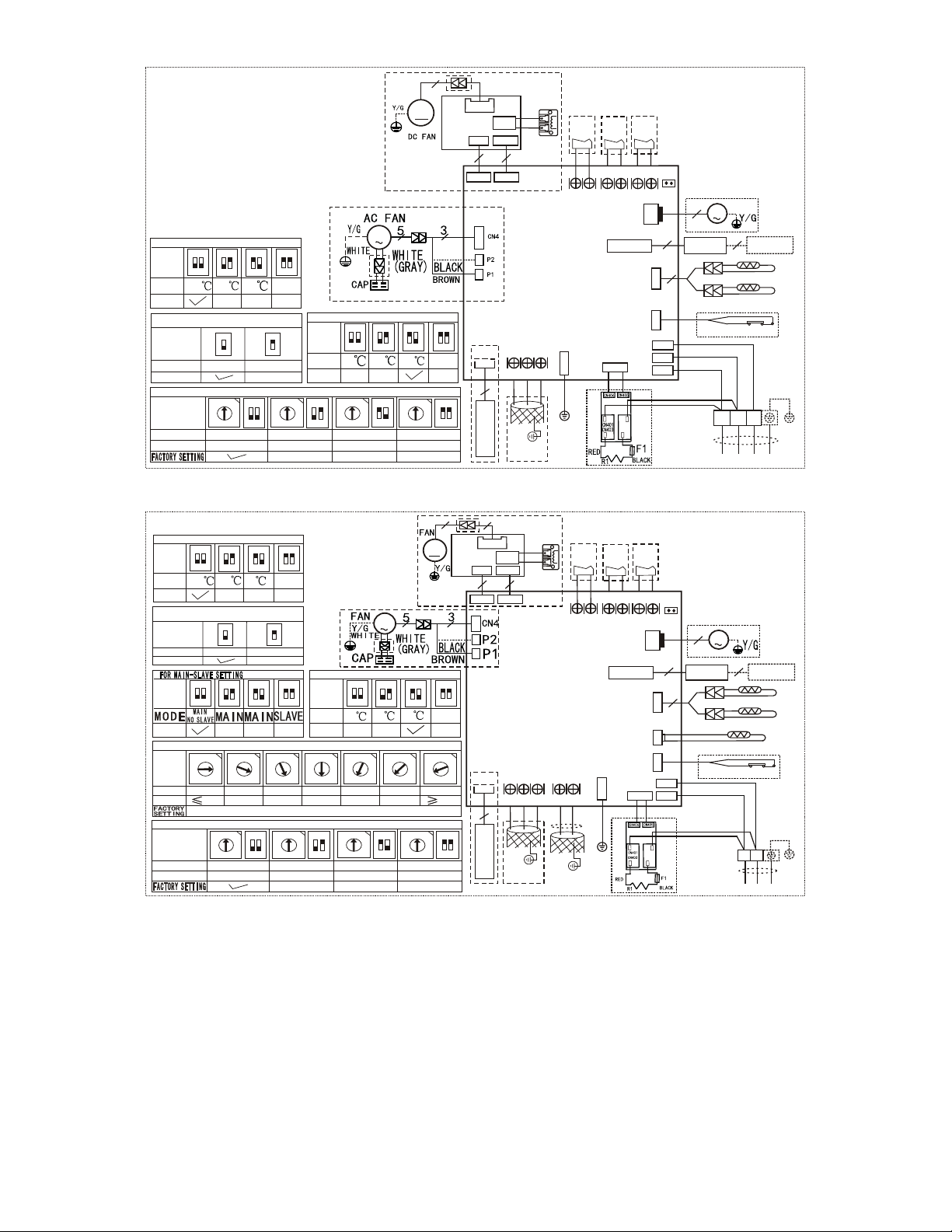
WIRING DIAGRAMS
0
8
4
1
2
3
5
6
7
C
9
A
B
D
E
F
0
8
4
1
2
3
5
6
7
C
9
A
B
D
E
F
0
8
4
1
2
3
5
6
7
C
9
A
B
D
E
F
0
8
4
1
2
3
5
6
7
C
9
A
B
D
E
F
S1+S2
0~F
0~F
0~F
0~F
NE TADDR E S S
CODE
0~15
16~31
32~47
48~63
FOR SET TING NETADDR ES S
EEPROM
DEFAULT
FACTOR Y
SETTING
FO R TE MP. CO MPE NS AT ION(HE ATING )
SW6
CODE
1
2
ON
SW1
TEL0
24
15
8
EEPROM
DEFAULT
FACTOR Y
SETTING
FOR ANTI-COLD WIND
1
ON
FACTORY SETTING
FOR SE TTING AUTO-R ES TART
SW3
MODE
AUTO-RESTART
NOT AUTO-RESTART
1
2
ON
1
2
ON
1
2
ON
1
ON
1
2
ON
1
2
ON
1
2
ON
1
2
ON
1
2
ON
1
2
ON
1
2
ON
1
2
ON
0
8
4
1
2
3
5
6
7
C
9
A
B
D
E
F
0
8
4
1
2
3
5
6
7
C
9
A
B
D
E
F
0
8
4
1
2
3
5
6
7
C
9
A
B
D
E
F
0
8
4
1
2
3
5
6
7
C
9
A
B
D
E
F
S1+S2
0~F
0~F
0~F
0~F
NETADDRE S S
CODE
0~15
16~31
32~47
48~63
FOR SET TING NETADDR ES S
0
8
4
1
2
3
5
6
7
C
9
A
B
D
E
F
0
8
4
1
2
3
5
6
7
C
9
A
B
D
E
F
0
8
4
1
2
3
5
6
7
C
9
A
B
D
E
F
0
8
4
1
2
3
5
6
7
C
9
A
B
D
E
F
0
8
4
1
2
3
5
6
7
C
9
A
B
D
E
F
0
8
4
1
2
3
5
6
7
C
9
A
B
D
E
F
0
8
4
1
2
3
5
6
7
C
9
A
B
D
E
F
ENC1
4
5
7
8
9
A
B
POWER
CODE
53
54~71
72~90
91~105
106~140
141~160
161
ACCORDING TO RE LATED MODEL.
FOR SETTING POWER(DC MOTOR MODEL ONLY)
1
2
ON
1
2
ON
1
2
ON
1
2
ON
SW1
TEL0
24
15
8
EEPROM
DEFAULT
FACTOR Y
SETTING
FOR ANTI-COLD WIND
EEPROM
DEFAULT
FACTOR Y
SETTING
FOR TEMP. COMPENSATION(HE ATING)
SW6
CODE
1
ON
1
ON
FACTORY SETTING
FOR SETTING AUTO-RES TAR T
SW3
MODE
AUTO-RESTART
NOT AUTO-RESTART
1
2
ON
FACTOR Y
SETTING
SW5
ON
12121
2
ON ON ON
1
2
ON
1
2
ON
1
2
ON
1
2
ON
1
2
ON
1
2
ON
1
2
ON
1
2
WIRING DIAGRAM
(INDOOR UNIT)
FOR ANTI-COLD WIND
TEL0
FACTOR Y
SETTING
FOR SE TTING AUTO-R ES TART
SW3
AUTO-RESTART
MODE
FACT ORY SETT ING
FOR SET TING NETADDR ES S
S1+S2
0~F
NETADDRE S S
0~15
EEPROM
DEFAULT
NOT AUTO-RESTART
0~F
FO R TE MP. CO MPE NS AT ION(HE ATING )
SW6
CODE
6
FACTOR Y
SETTING
ON
16~31
0~F
32~47
Fig. 8 – Wiring Diagram Sizes 18−24
M
2
3
M
DRIVER MODLE
ON
ON
EEPROM
4
DEFAULT
ON
0~F
48~63
DC MOTOR
CN34
FAN1
CN1
4
CN40
4
E
WIR
R
NTROLLE
O
C
CON 2
CON1
CN15
3
CN9
X Y E
To CCM
Comm.B us
FAN FOR THE
FRESH AIR
OR ANION
GENERATOR
RED
RED
Reactor
CN43
INDOOR UNIT
MAINBOARD
N18
C
YELLOW
Y/G
Alarm
Output
ALARM
CN33
CN1 3
CN12
L402
R
HEATE R
Remote
Control
ON/OFF
CN23
CN1 0
CN6
CN5
YELLOW
401
RL
CN402
CN404
NOTE:
1.The parts with dotted line indicates
optional features.
2.Remove the short connector of J7
when you use the "on-off" function.
J7
PUMP
2
M
10
DISPL AY
4
5
BOAR D
INDOOR COIL TEMP. SENSOR
BLACK
ROOM TEMP. SENSOR
WHITE
WATER LEV EL SW ITCH
CN3
YELLOW(WHITE)
CN2
BLACK
CN1
RED
BLACK
RED
L1
MAGNETIC
L2
RING
TO OUTDOOR UNIT
WIRE
CONTROLLER
T2
T1
Y/G
S
WIRING DIAGRAM
FOR ANTI-COLD WIND
SW1
TEL0
FACTOR Y
SETTING
FOR SE TTING AUTO-RE START
SW3
MODE
FACTORY SETTING
FACTOR Y
SETTING
FOR SETTING POWER(DC MOTOR MODEL ONLY)
ENC1
POWER
S1+S2
NETADDRE S S
FOR SETTING NETADDRESS
CODE
15
AUTO-RESTART
EEPROM
DEFAULT
NOT AUTO-RESTART
FOR TEMP. COMPENSATION(HE ATING)
SW6
CODE
FACTOR Y
SETTING
0~F
91~105
54~71
ACCORDING TO RELATED MODEL.
0~F
0~15
3
3
M
FA N1
DC MOTOR
DRIVER MODLE
CN1
4
CN3 4
CON2
CO N1
3
CN1 5
M
INDOOR UNIT
MAINBOARD
CN 9
CN40
X Y E
6
106~140
2
141~160
EEPROM
4
DEFAULT
4
0~F
32~47
0~F
48~63
WIRE
CONTROLLER
To C CM
C omm.B us
Fig. 9 – Wiring Diagram Size 36−48
11
RED
RED
REACTOR
TO OUTDOOR
COMM.BUS
FAN FOR THE
FRESH AIR
OR ANION
GENERATOR
CN 20
S2 S1
•••• • • • • • ••
•••••• •• •
CN 43
Y/G
ALAR M
OUTPUT
ALAR M
CN 33
CN13
CN10
18
N
C
YELLOW
REMOTE
CONTROL
ON/OFF
CN 23
CN6
CN7
CN5
CN1 2
RL402
EA
H
NOTE:
1.The parts with dotted line indicates
optional features.
2.Remove the short connector of J7
when you use the "on-off" function.
J7
2
10
DISPLAY
BOARD
4
BLACK
WHITE
INDOOR COIL OUTLET TEMP. SENSOR
CN2
BLACK
CN1
RED
BLACK
RED
MAGNETIC
RING
L401
R
CN402
CN404
TER
YELLOW
PUMP
M
WIRE
5
CONTROLLER
INDOOR COIL TEMP. SENSOR
WATER LEVE L SWITC H
T2
ROOM TEMP. SENSOR
T1
T2B
Y/G
L1
L2
TO OUTDOOR UNIT
Page 12
GUIDE SPECIFICATIONS
INDOOR CEILING−MOUNTED DUCTED STYLE DUCTLESS UNITS
Size Range: 1.5 to 4 Ton Nominal Cooling and Heating Capacity
Model Number: 40MBDQ
PART 1 − GENERAL
1.01 System Description
Indoor, ceiling−mounted, direct−expansion fan coils are matched
with a heat pump outdoor unit.
1.02 Agency Listings
Unit is rated per AHRI Standards 210/240 and listed in the AHRI
directory as a matched system.
1.03 Delivery, Storage, And Handling
Units are stored and handled per unit the manufacturer’s
recommendations.
1.04 Warranty (For Inclusion By Specifying
Engineer)
PART 2 − PRODUCTS
2.01 Equipment
A. General:
Indoor, direct−expansion, ceiling−mounted fan coil. The unit is
complete with cooling/heating coil, fan, fan motor, piping
connectors, electrical controls, microprocessor control system, and
integral temperature sensing.
B. Unit Cabinet:
Unit cabinet is constructed of galvanized steel. The cabinet is fully
insulated for improved thermal and acoustic performance.
C. Fans:
The fan is tangential direct−drive blower type with air intake at the
rear or bottom of the unit and discharge at the front.
D. Coil:
The coil is a copper tube with aluminum fins and galvanized steel
tube sheets. The fins are bonded to the tubes by mechanical
expansion and specially blue hydrophilic pre−coated for enhanced
wet−ability. A drip pan under the coil has a factory installed
condensate pump and drain connection for hose attachment to
remove condens a t e .
E. Motors:
The motors has an open drip−proof, permanently lubricated ball
bearing with inherent overload protection. Fan motors are 3−speed.
F. Controls:
The controls consist of a microprocessor−based control system
which controls the space temperature, determines optimum fan
speed, and runs self diagnostics. The temperature control range is
62_F to 86_F (17_C to 30_C) in increments of 1_F or 1_C, and
has a 46_F Heating Mode (Heating Setback). The wireless remote
controller can act as the temperature sensing location for room
comfort.
The unit has the following functions as a minimum:
1. An automatic restart after power failure at the same
operating conditions as at failure.
2. A timer function to provide a minimum 24−hour timer
cycle for system Auto Start/Stop.
3. Temperature−sensing controls sense return air temperature.
4. Indoor coil freeze protection.
5. Wireless infrared remote control to enter set points and
operating conditions.
6. Dehumidification mode provides increased latent removal
capability by modulating system operation and set point
temperature.
7. Fan−only operation to provide room air circulation when no
cooling is required.
8. Diagnostics provide continuous checks of unit operation
and warn of possible malfunctions. Error messages appear
on the unit.
9. The fan speed control is user−selectable: high, medium,
low, or microprocessor controlled automatic operation
during all operating modes.
10. Automatic heating−to−cooling changeover in heat pump
mode. The control includes deadband to prevent rapid mode
cycling between heating and cooling.
11. Indoor coil high temperature protection is provided to detect
an excessive indoor discharge temperature when unit is in
the heat pump mode.
G. Electrical Requirements:
The indoor fan motor operates on 208−230V. Power is supplied
from the outdoor unit.
H. Operating Characteristics:
The 40MBDQ system has a minimum SEER (Seasonal Energy
Efficiency Ratio) and HSPF at AHRI conditions, as listed on the
specifications table.
I. Refrigerant Lines:
All units have refrigerant lines that can be oriented to connect from
the side of the unit. Both refrigerant lines need to be insulated.
Copyright 2017 Carrier Corp. D 7310 W. Morris St. D Indianapolis, IN 46231 . Edition Date: 02/17
Manufacturer reserves the right to change, at any time, specifications and designs without notice and without obligations.
12
Catalog No: 40MBDQ-01PD
Replaces: NEW
 Loading...